Abstract
Micro-arc oxidation (MAO) coatings were obtained from an AZ91D magnesium alloy at different oxidation times (5, 10, 15, and 20 min), using a zirconium salt electrolyte system, with (NH4)2ZrF6 as the main salt. The morphology of the coatings was studied using a scanning electron microscope (SEM) and confocal laser scanning microscopy (CLSM). Energy dispersive spectrometry (EDS), X-ray diffractometry (XRD), and X-ray photoelectron spectroscopy (XPS) were employed to determine the type of element and the composition of its phase. The potentiodynamic polarization curve (PDP) was applied to illustrate the corrosion resistance of the coatings. We found the coatings had minor porosity and the best compactness when the MAO treatment time was 10 min. The coatings mainly comprised MgO, ZrO2, MgF2, and Zr3O2F8 phases and amorphous magnesium phosphate. Among the MAO coatings prepared in this experiment, the 10 min coating had the lowest corrosion current density (Icorr), and the Icorr was 4.864 × 10⁻⁸ A/cm2, which was three orders of magnitude lower than the uncoated AZ91D magnesium alloy.
1. Introduction
Magnesium alloys are suitable for application in aerospace, vehicles, electronic products, biomedical metals, and other fields, because of their low density, high specific strength and stiffness, excellent electromagnetic shielding performance, good shock absorption performance, and good biocompatibility [1,2,3]. Unfortunately, their applicability has always been constrained by the fatal flaw of weak corrosion resistance. Therefore, researchers have studied various anti-corrosion technologies to solve this problem, such as heat treatment [4], corrosion inhibition [5,6], chemical conversion [7], electroplating/electroless plating [8,9], micro-arc oxidation [10], vapor deposition [11], and laser surface treatment [12], etc.
Micro-arc oxidation (MAO), one of the many surface protection technologies, is regarded as one of the most promising surface treatment methods for magnesium alloys due to its straightforward procedure, environmental friendliness, capability to treat intricately shaped workpieces, and ability to create a coating with good corrosion resistance. MAO’s basic principle is to apply high voltage to a metal immersed in an electrolyte to cause a breakdown of micro-arc discharge on its surface. Under local high temperatures and high voltage, the metal surface is oxidized to generate ceramic coatings of matrix element oxides and electrolyte-element-doped oxides in situ [13]. After years of research by researchers, it is generally agreed that the performance of micro-arc oxidation films is affected by electrical parameters (voltage, current density, frequency, and duty cycle), oxidation time, electrolyte type, and electrolyte concentration [2,14,15,16].
Zirconium dioxide, which has stable chemical properties, high-temperature resistance, and corrosion resistance, can be introduced into the micro-arc oxidation coating as an oxide to improve the corrosion resistance of the coating. In recent years, numerous studies have reported the preparation of MAO coatings on magnesium alloys in zirconium salt electrolytes. Einkhah et al. [17] generated the zirconium-containing oxide layer on an AZ31 magnesium alloy using a two-step method, which significantly improved the corrosion resistance of the coating. Tang et al. [18] prepared a ZrO2-Mg2ZrO12-MgO composite MAO coating on an AZ91D magnesium alloy by adding ZrO2 nanoparticles to a phosphate solution containing 10 g/L K2ZrF6. The result showed that adding ZrO2 nanoparticles further improved the coating’s thickness, compactness, and corrosion resistance. Selvi et al. [19] reported the effects of different electrolytes (NaSiO3 and NaAlO2 + Na3PO4 mixed with K2ZrF6 and Na2ZrO3 zirconium salts, respectively) and different voltages on the morphology and the property of an MAO coating on an AZ91D magnesium alloy.
Oxidation time is an essential parameter in controlling the structure and properties of coatings in the MAO process, which affect the surface morphology, roughness, friction and wear properties, and corrosion resistance of the coatings. Rehman et al. [20] prepared MAO coatings with different time intervals on an AZ31B magnesium alloy in a Na2SiO3-K2ZrF6 hybrid electrolyte. The coatings comprised MgF2, ZrO2, Mg2SiO4, and MgO phases. The hardness and corrosion resistance were significantly improved with the extension of the treatment time, and the best corrosion resistance was obtained at 15 min. Yong et al. [21] learned through orthogonal experimental research that the MAO coating of a ZK61M alloy had the best corrosion resistance at a 6 g/L (NH4)2ZrF6 concentration, 450 V voltage, and 15 min oxidation time.
Researchers have researched the MAO process of a magnesium alloy in an electrolyte, using K2ZrF6 as the main salt. However, the research information on the role of oxidation time in the (NH4)2ZrF6 electrolyte system was limited. In this paper, the MAO ceramic coating of an AZ91D magnesium alloy was fabricated in a (NH4)2ZrF6 electrolyte, and the effect of different oxidation times on the microstructure and corrosion resistance of the coating was studied, which provided a valuable exploration for the micro-arc oxidation corrosion protection treatment of the magnesium alloy.
2. Materials and Methods
2.1. Sample Pretreatment and Coating Preparation
The size of the AZ91D magnesium alloys used in the experiment was 15 × 15 × 3 mm. The element content we tested is shown in Table 1.

Table 1.
Element content of AZ91D magnesium alloy.
Before the MAO treatment, we used 800 grit, 1000 grit, 1500 grit, and 2000 grit abrasive paper to polish the surfaces of the samples until the surfaces were bright and without apparent scratches. Next, the pieces were ultrasonically cleaned with ethanol and acetone for 10 min, rinsed with deionized water, and dried in cold air for standby.
2.2. Experiment Process
The equipment used in the MAO treatment was a T-25Z thick film oxidation machine (Northwest Institute for Nonferrous Metal Research, Xi’an, China), mainly composed of a power supply, electrolytic cell, agitator, and refrigerant. The electrolyte components were: (NH4)2ZrF6, NaH2PO4, NaF, and NaOH. NaOH was mainly used to adjust the pH value of the solution (7.5–8.0). The electrical parameters used in the MAO were a voltage of 450 V, a frequency of 500 Hz, a duty cycle of 15%, and different oxidation times of 5 min, 10 min, 15 min, and 20 min.
2.3. Characterization Method
A VEGA II XMU scanning electron microscope (SEM, Tescan, Oxford, UK) was used to observe the surface and cross-sectional morphologies of the coatings, and the energy dispersive spectrometer (EDS) was employed to analyze the element species and element distribution on the surfaces and cross-sections.
Zeiss LSM800 confocal laser scanning microscopy (CLSM, Zeiss, Oberkochen, Germany) was used to measure the three-dimensional surface morphology of the coatings, with a selected area of 255 × 255 μm.
The phase composition of the coatings was determined by a D/max 2200 PC X-ray diffractometer (XRD, RIGAKU, Tokyo, Japan) under the Cu Kα radiation of 45 kV and 200 mA, and the detection angle was set at a 2θ range of 10°–80° with a step size of 0.02° and a scanning speed of 2°/min.
Dimension Icon type X-ray photoelectron spectroscopy (XPS, Bruker, Billerica, MA, USA) analyzed the chemical states of the coating constituent elements.
The potentiodynamic polarization (PDP) curve was measured with a VersaSTAT 3F electrochemical workstation (AMETEK, Berwyn, PA, USA). The electrochemical workstation used the typical three-electrode system, with a saturated calomel electrode (SCE) as the reference electrode, a platinum grid as the counter electrode, and the sample as the working electrode. According to the set step time and step height (which determined the scanning rate), the PDP curve of the sample was obtained by scanning from the initial to the final potentials. Before measuring the PDP curve of each coating, the samples were sealed with modified acrylate adhesive, and the surfaces were exposed to a working area of 1 × 1 cm2. Then, the samples were immersed in a 3.5 wt.% NaCl solution for 20 min, with the temperature kept at room temperature. The PDP curves were tested with a potential scanning region of −0.5–1.5 V and a scan rate of 2 mV/s.
3. Results and Discussion
3.1. Surface and Cross-Sectional Morphology of MAO Coatings
The surface morphologies of the MAO coatings prepared by different oxidation times are shown in Figure 1. The MAO coating surfaces showed an irregular porous convex morphology with deposits appearing in some pores, and the molten oxides were in a radially extending state. With the prolongation of the reaction time, the continuous stacking and covering of the molten oxides closed the reaction micropores, and the multi-layer pore structure of large pores covering tiny pores appeared on the surfaces of the coatings (Figure 1d).
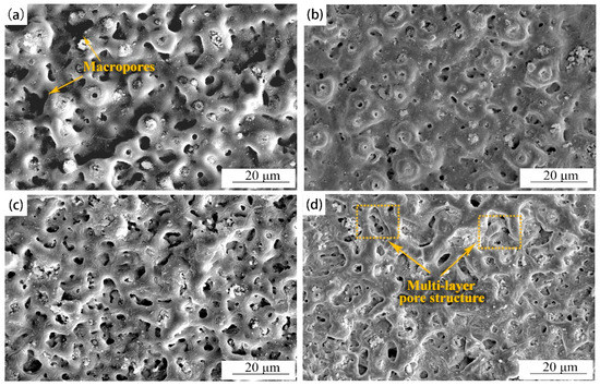
Figure 1.
Surface morphologies of MAO coatings with different oxidation times: (a) 5 min; (b) 10 min; (c) 15 min; (d) 20 min.
The porosity of each coating was analyzed by ImageJ software, and the porosity of each coating showed apparent differences with the increase in oxidation over time (Figure 2). At 5 min, the porosity of the coating was the largest, and the coating had a minor porosity at 10 min. In the initial reaction stage, the MAO coating surfaces had violent oxidation reactions, accompanied by micro-discharge breakdown and gas release. Thus, some macropores, coupled with multiple discharge micropores, were generated on the MAO coating surfaces (Figure 1a). The molten oxides on the surfaces of the substrates were sprayed to the outside under local high temperature and electric voltage, and large sintering protrusions were formed by the cooling of the external electrolyte (Figure 1a) [22,23]. The pores on the coating surfaces became significantly smaller at 10 min, due to the accumulation of molten oxides and the sealing effect of the deposits on the pores (Figure 1b) [24]. When the time increased to 15 or 20 min, the oxidation degree of the coating became weakened, and the insulation was increased, resulting in partial micro-arc discharge on the surface. During this process, the discharge channels became smaller and energy accumulated gradually, causing the coatings to break and deteriorate. Therefore, the micropores of the coatings increased, and microcracks of different degrees accompanied the surfaces (Figure 1c,d) [25].
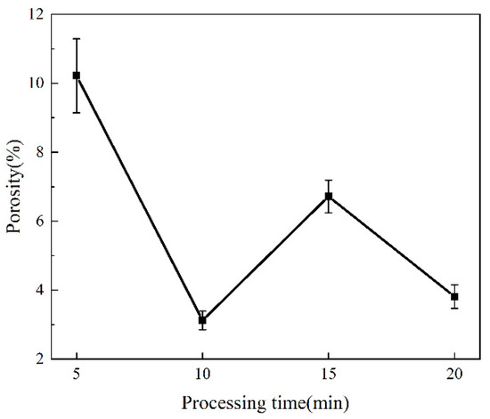
Figure 2.
Porosity change of MAO coatings at different treatment times.
Three-dimensional surface morphologies of MAO coatings are displayed in Figure 3. The color differences of the images reflected the undulation of the coating surfaces to a certain extent. The more significant the color difference, the higher the undulation of the MAO coatings [26]. There were many blue areas on the surface of the micro-arc oxidation film at 5 min (Figure 3a), and many noticeably large particles could be seen, indicating that the coating surface fluctuated wildly. With the extension of the oxidation time, it can be seen that the color difference of the coatings gradually decreased, and the convex particles became smaller and flatter. The surfaces of the coatings gradually became smoother (Figure 3b–d).
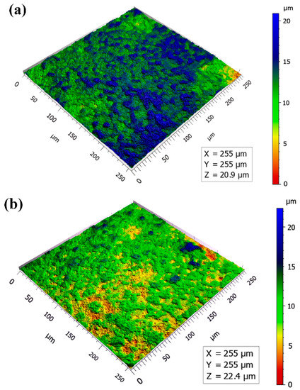
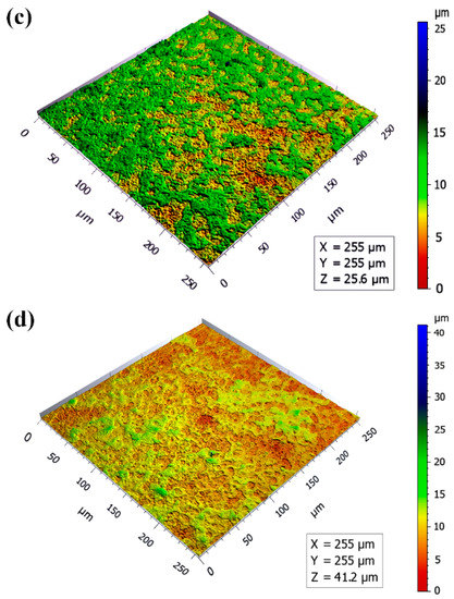
Figure 3.
Three-dimensional surface morphologies of MAO coatings: (a) 5 min; (b) 10 min; (c) 15 min; (d) 20 min.
The cross-sectional morphologies of the MAO coatings formed under different oxidation time conditions are illustrated in Figure 4. It can be shown that the increase in the thickness of the coatings was not apparent with the extension of the treatment time, the interfaces between coating and substrate were tightly bonded, and there was no evident cracking.
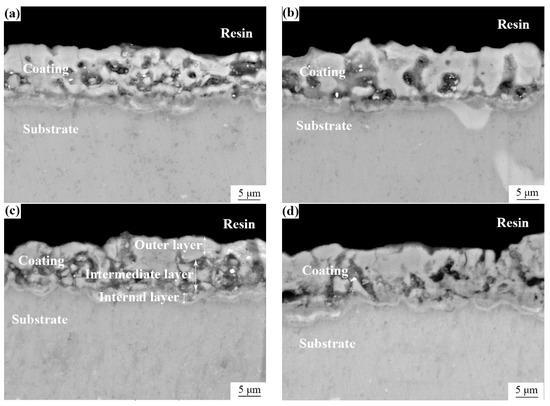
Figure 4.
Cross-sectional morphologies of MAO coatings: (a) 5 min; (b) 10 min; (c) 15 min; (d) 20 min.
As we all know, a traditional MAO coating generally comprises a dense inner layer and an outer porous layer. However, it is evident from the cross-sections of the MAO coatings described in Figure 4 that pore defects were primarily distributed in the middle of the coatings, and some pores were internally mixed with deposits. The coatings could be roughly divided into a skinny internal barrier layer, a thick but porous intermediate layer, and a relatively dense outer layer (Figure 4c). We speculated that the formation of this structure was due to the filling and covering of the pores by molten materials during the growth of the micro-arc oxidation coatings. Still, some works from the literature believed that it was due to the difference in the transient temperature field of the inner and outer layers [20,27].
By comparing the coatings, it was found that the number of hole defects in the intermediate layer of the coating was relatively small when the treatment time was 10 min. There were no noticeable penetrating pores and microcracks, and the structure was pretty dense, which also coincided with the surface morphology shown in Figure 1b.
3.2. Composition Analysis of MAO Coatings
EDS surface scanning analysis was carried out on the MAO coatings under different time conditions to understand the main elements on the surfaces of the MAO coatings and their relative contents. The results are listed in Table 2. The coatings were mainly composed of O, F, Mg, Zr, and P elements, indicating that the components in the electrolyte were successfully incorporated into the layers. It was speculated that MgO, ZrO2, MgF2, phosphate, and other substances were generated in the coatings. Some in the literature revealed that the presence of the F element could improve the compactness of the coating, and MgF2, as a stable product, played a dissolution inhibition role and reduced the pitting tendency, thus providing better protection for the MAO coating [28,29]. ZrO2 has high strength and fracture toughness, a low coefficient of thermal expansion, and good corrosion resistance. Its chemical stability in neutral or acidic solutions is higher than that of MgO. The introduction of ZrO2 has been beneficial in improving the corrosion resistance of the MAO coating [20,30,31].
Table 2.
EDS analysis data of MAO coating surface at different times.
The EDS line scan images of the 10 min coating are shown in Figure 5, which show the distribution of the various elements in the coating cross-section. It can be seen that the F, O, Zr, and P elements were mainly concentrated in the generated coating. The Zr and F elements showed more distribution in the loose intermediate layer, indicating that the ZrO2 and MgF2 contents around the coating defects were higher and played a role in filling the pores, which is consistent with previous literature studies [24,32].

Figure 5.
EDS line scan spectrum of 10 min coating: (a) full spectrum; (b) F; (c) Zr; (d) O; (e) Mg; (f) P.
3.3. Phase Analysis of MAO Coatings
To further determine the phase compositions of the MAO coatings, XRD analysis was carried out on the coatings. MDI jade software detected several diffraction peaks of ZrO2, MgO, MgF2, and Zr3O2F8 (Figure 6), indicating that the coating consisted of ZrO2, MgO, MgF2, and Zr3O2F8 phases.

Figure 6.
XRD pattern of MAO coatings with different oxidation times.
The XPS spectra of the MAO coatings are described in Figure 7. According to the complete spectrum analysis, the main constituent elements of these surface layers were Mg, Na, F, O, Zr, and P (Figure 7a). The specific binding energies of the F, O, Mg, and Zr in each MAO coating are shown in Figure 7b–e. The F1s peak at 685.75 eV corresponded to the MgF2; O 1s was divided into two peaks; the peak at 531.30 eV corresponded to the ZrO2; and the peak at 532.10 eV corresponded to the MgO. The three peaks of Mg1s appeared at the binding energies 1303.90 eV, 1304.95 eV, and 1306.50 eV, of which 1306.50 eV and 1304.95 eV were attributed to the MgF2, and 1303.90 eV was from the MgO. The Zr 3d spectrum was divided into three peaks. Two peaks of the Zr 3d3/2 were at 185.50 eV and 184.50 eV, and one peak of the Zr 3d5/2 was at 182.90 eV, which are all attributed to the ZrO2. The phase detection results of the XRD were further verified by XPS spectrum analysis.
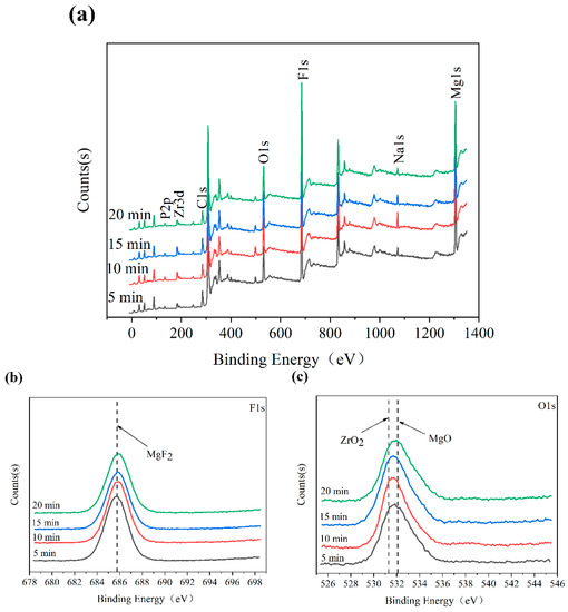
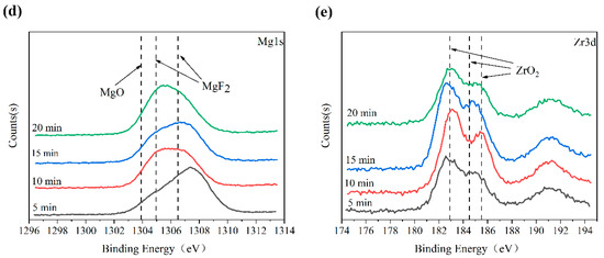
Figure 7.
XPS spectra of MAO coatings: (a) full spectrum; (b) F 1s; (c) O 1s; (d) Mg 1s; (e) Zr 3d.
It is well known that many complex chemical oxidations, electrochemical oxidations, and plasma oxidations coexisted in the MAO reactions of the valve metals, which involved complex processes, such as chemistry, electrochemistry, thermodynamics, and metallurgy. Combined with the detection results of the XRD and XPS, we conjectured that the following reactions might have been involved in the formation stage of the MAO coatings [20,33]:
We observed that there were Zr3O2F8 phases in the coatings, due to the fluorination of the ZrO2 by NH4F under the joint actions of reaction temperature, reaction time, and different electrolytes in the micro-arc oxidation process. The reaction formula is as follows [34]:
ZrO2 + NH4F→ZrOxF4−2x + NH3 + H2O
In addition, the presence of the P element in the coating was detected by EDS (Table 1), indicating that the electrolyte NaH2PO4 also participated in the reactions of coating formation. However, we did not find the diffraction peak of the related phosphate (Mg3(PO4)2) through XRD detection, which indicated that the amorphous phases of magnesium phosphate were likely formed in the coatings [24,32,35].
3.4. Electrochemical Corrosion Test
We used the Tafel extrapolation method to deduce the corrosion parameters of the samples from the polarization curve, which included the corrosion potential Ecorr, the corrosion current density Icorr, the anode Tafel slope βa, and the cathode Tafel slope βc. The polarization resistance Rp was calculated by the Stern–Geary formula, and described as follows:
Rp = βa·|βc|/[2.303·Icorr(βa + |βc|)]
The corrosion rate Vcorr (expressed as penetration rate vp) was calculated by the formulas described as follows, where A represents the molar mass of the main element Mg (24.30 g/mol), and ρ represents the density of the Mg (1.74 g/cm3) and z = 2 [36]:
vp = 3.27 × (A/z)·(Icorr/ρ)
Figure 8 shows the polarization curves of the AZ91D magnesium alloy bare substrate and its MAO coatings, with the electrochemical data obtained by the Tafel extrapolation method and the Stern–Geary formula listed in Table 3.
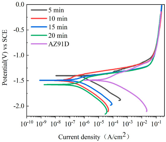
Figure 8.
Potentiodynamic polarization curves of AZ91D magnesium alloy and MAO coatings in 3.5 wt.% NaCl solution under different oxidation times.
Table 3.
Parameter values of potentiodynamic polarization curves of AZ91D magnesium alloy and MAO coatings in 3.5 wt.% NaCl solution.
Generally, we believe that high corrosion potential (Ecorr) and low corrosion current density (Icorr) represent good corrosion resistances for the test samples. From the polarization curve and electrochemical data, we could see that the increase in oxidation time did not significantly improve the Ecorr of the coatings, and the Ecorr of some coatings was more negative than that of the uncoated bare substrate. This situation was attributed to the MAO coatings having a more significant inhibition effect on the cathode reactions than on the anode reactions, which makes the coatings exhibit a more negative corrosion potential [37]. Therefore, the Icorr and Rp could better reflect the change in the corrosion resistance of the MAO coatings.
From the data in Table 3, we can see that, compared with the AZ91D magnesium alloy bare substrate, the Icorr of the MAO coatings was generally reduced by 2–3 orders of magnitude, and the polarization resistance Rp increased by 1–2 orders of magnitude, and the corrosion rate Vcorr reduced by 1–2 orders of magnitude. The samples under 10 min treatment had the lowest Icorr (4.864 × 10⁻⁸ A/cm2), the most extensive Rp (4.710 × 10⁵ kΩ·cm2), and the minimum Vcorr (1.11 µm/year), which proved that the coating obtained under the 10 min treatment had the best corrosion resistance. The reason was that the 10 min coating with low porosity and fewer structural defects (Figure 1b) could more effectively block the penetration of corrosive media into the substrate [38]. In addition, the MgF2 and zirconium-containing oxides in the coating also played a particular role in improving the corrosion resistance of the coating.
4. Conclusions
MAO ceramic coatings of the AZ91D magnesium alloy were prepared in the electrolyte (NH4)2ZrF6 as the main salt under 5 min, 10 min, 15 min, and 20 min oxidation times. The following conclusions were drawn from the study of the microstructure, phase composition, and corrosion resistance of the coatings:
- The coating with the 10 min oxidation time had the lowest porosity, the fewest defects, and the best compactness.
- The MAO coatings of the AZ91D magnesium alloy formed in the (NH4)2ZrF6 electrolyte were mainly composed of MgO, ZrO2, MgF2, Zr3O2F8, and amorphous magnesium phosphate.
- The 10 min MAO coating had the best corrosion resistance. The corrosion current density of the 10 min MAO coating was 4.864 × 10⁻⁸ A/cm2, which was three orders of magnitude lower than that of the uncoated magnesium alloy. The polarization resistance of the 10 min MAO coating was 4.710 × 10⁵ kΩ·cm2, which was two orders of magnitude higher than that of the uncoated magnesium alloy.
In general, the experimental results clearly showed that the corrosion resistance of the MAO coatings was closely related to the oxidation time. Too short or too long of an oxidation time reduced the quality of the MAO coating. It was necessary to adjust the oxidation time in MAO treatments to obtain the best quality coating. In addition, although MAO coating significantly increased the corrosion resistance of the AZ91D magnesium alloy, it still had some limitations, so other coatings for hole sealing treatment should also be considered.
Author Contributions
Conceptualization, formal analysis, H.L. and Z.L.; methodology, validation, H.L. and Y.W.; software, Y.W., J.G. and J.Z.; resources, supervision, project administration, funding acquisition, H.L. and Y.C.; date curation, J.Z., J.G.; investigation, writing—original draft preparation, visualization, J.Z.; writing—review and editing, Y.C. All authors have read and agreed to the published version of the manuscript.
Funding
This research was supported by the Major Science and Technology Project of Shaanxi Province, grant number: 2020zdzx04-03-02.
Institutional Review Board Statement
Not applicable.
Informed Consent Statement
Not applicable.
Data Availability Statement
Not applicable.
Conflicts of Interest
The authors declare no conflict of interest.
References
- Song, J.F.; Chen, J.; Xiong, X.M.; Peng, X.D.; Chen, D.L.; Pan, F.S. Research advances of magnesium and magnesium alloys worldwide in 2021. J. Magnes. Alloys 2022, 10, 863–898. [Google Scholar] [CrossRef]
- Bai, L.J.; Dong, B.X.; Chen, G.T.; Xin, T.; Wu, J.N.; Sun, X.D. Effect of positive pulse voltage on color value and corrosion property of magnesium alloy black micro-arc oxidation ceramic coating. Surf. Coat. Technol. 2019, 374, 402–408. [Google Scholar] [CrossRef]
- Echeverry-Rendon, M.; Duque, V.; Quintero, D.; Harmsen, M.C.; Echeverria, F. Novel coatings obtained by plasma electrolytic oxidation to improve the corrosion resistance of magnesium-based biodegradable implants. Surf. Coat. Technol. 2018, 354, 28–37. [Google Scholar] [CrossRef]
- Xu, H.; Li, Y.; Wu, L.; Jiang, F.; Fu, D.; Teng, J.; Zhang, H. Effect of Heat Treatments on the Corrosion Resistance of a High Strength Mg-Gd-Y-Zn-Zr Alloy. Materials 2022, 15, 2813. [Google Scholar] [CrossRef] [PubMed]
- Malinowski, S.; Jaroszynska-Wolinska, J.; Herbert, T. Theoretical predictions of anti-corrosive properties of THAM and its derivatives. J. Molec. Model. 2018, 24, 1. [Google Scholar] [CrossRef] [PubMed]
- Malinowski, S.; Wrobel, M.; Woszuk, A. Quantum Chemical Analysis of the Corrosion Inhibition Potential by Aliphatic Amines. Materials 2021, 14, 6197. [Google Scholar] [CrossRef]
- Li, T.; Wang, S.F.; Liu, H.T.; Wu, J.H.; Tang, S.Q.; Yang, Y.S.; Wang, X.T.; Zhou, J.X. Improved corrosion resistance of Mg alloy by a green phosphating: Insights into pre-activation, temperature, and growth mechanism. J. Mater. Sci. 2020, 56, 828–843. [Google Scholar] [CrossRef]
- Carrillo, D.F.; Bermudez, A.; Gomez, M.A.; Zuleta, A.A.; Castano, J.C.; Mischler, S. Fretting-corrosion behavior of electroless Ni-P/Ni-P-TiO2 coatings obtained on AZ91D magnesium alloy by a chromium-free process. Surf. Inter. 2020, 21, 100733. [Google Scholar] [CrossRef]
- Singh, C.; Tiwari, S.K.; Singh, R. Exploring environment friendly nickel electrodeposition on AZ91 magnesium alloy: Effect of prior surface treatments and temperature of the bath on corrosion behaviour. Corros. Sci. 2019, 151, 1–19. [Google Scholar] [CrossRef]
- Liu, S.Q.; Li, G.H.; Qi, Y.M.; Peng, Z.J.; Ye, Y.P.; Liang, J. Corrosion and tribocorrosion resistance of MAO-based composite coating on AZ31 magnesium alloy. J. Magnes. Alloys 2021. [Google Scholar] [CrossRef]
- Gao, Z.Y.; Yang, D.; Sun, C.J.; Du, L.T.; Zhang, X.; An, Z.G. The Corrosion Resistance of Al Film on AZ31 Magnesium Alloys by Magnetron Sputtering. Metals 2021, 11, 1522. [Google Scholar] [CrossRef]
- Pou-Alvarez, P.; Riveiro, A.; Novoa, X.R.; Fernandez-Arias, M.; Del Val, J.; Comesana, R.; Boutinguiza, M.; Lusquinos, F.; Pou, J. Nanosecond, picosecond and femtosecond laser surface treatment of magnesium alloy: Role of pulse length. Surf. Coat. Technol. 2021, 427, 127802. [Google Scholar] [CrossRef]
- Darband, G.B.; Aliofkhazraei, M.; Hamghalam, P.; Valizade, N. Plasma electrolytic oxidation of magnesium and its alloys: Mechanism, properties, and applications. J. Magnes. Alloys 2017, 5, 74–132. [Google Scholar] [CrossRef]
- Dehnavi, V.; Luan, B.L.; Shoesmith, D.W.; Liu, X.Y.; Rohani, S. Effect of duty cycle and applied current frequency on plasma electrolytic oxidation (PEO) coating growth behavior. Surf. Coat. Technol. 2013, 226, 100–107. [Google Scholar] [CrossRef]
- Al Bosta, M.M.S.; Ma, K.J.; Chien, H.H. The effect of MAO processing time on surface properties and low temperature infrared emissivity of ceramic coating on aluminum 6061 alloy. Inf. Phys. Technol. 2013, 60, 323–334. [Google Scholar] [CrossRef]
- Zhao, Z.Q.; Pan, Q.L.; Yan, J.K.; Ye, J.; Liu, Y. Direct current micro-arc oxidation coatings on Al-Zn-Mg-Mn-Zr extruded alloy with tunable structures and properties templated by discharge stages. Vacuum 2018, 150, 155–165. [Google Scholar] [CrossRef]
- Einkhah, F.; Lee, K.M.; Sani, M.A.F.; Yoo, B.; Shin, D.H. Structure and corrosion behavior of oxide layer with Zr compounds on AZ31 Mg alloy processed by two-step plasma electrolytic oxidation. Surf. Coat. Technol. 2014, 238, 75–79. [Google Scholar] [CrossRef]
- Tang, M.Q.; Shao, Y.F.; Feng, Z.Q.; Wang, W.; Li, G.; Yan, Z.W.; Zhang, R.Z. Self-sealing Microarc Oxidation Coating Mainly Containing ZrO2 and Nano Mg2Zr5O12 on AZ91D Mg Alloy. Int. J. Electrochem. Sci. 2020, 15, 12447–12461. [Google Scholar] [CrossRef]
- Selvi, E.; Muhaffel, F.; Yurekturk, Y.; Vanli, A.S.; Baydogan, M. Influence of Electrolyte Compositions and Electrical Parameters on Thermal Properties of Micro-Arc Oxidized AZ91 Alloy. J. Mater. Eng. Perform. 2021, 31, 1667–1678. [Google Scholar] [CrossRef]
- Rehman, Z.U.; Shin, S.H.; Hussain, I.; Koo, B.H. Investigation of hybrid PEO coatings on AZ31B magnesium alloy in alkaline K2ZrF6-Na2SiO3 electrolyte solution. Prot. Met. Phys. Chem. Surf. 2017, 53, 495–502. [Google Scholar] [CrossRef]
- Yong, J.H.; Li, H.Z.; Li, Z.X.; Chen, Y.N.; Wang, Y.F.; Geng, J.J. Effect of (NH4)2ZrF6, Voltage and Treating Time on Corrosion Resistance of Micro-Arc Oxidation Coatings Applied on ZK61M Magnesium Alloys. Materials 2021, 14, 7410. [Google Scholar] [CrossRef] [PubMed]
- Chang, L.; Tian, L.; Liu, W.; Duan, X. Formation of dicalcium phosphate dihydrate on magnesium alloy by micro-arc oxidation coupled with hydrothermal treatment. Corros. Sci. 2013, 72, 118–124. [Google Scholar] [CrossRef]
- Guo, H.; An, M.; Xu, S.; Huo, H. Formation of oxygen bubbles and its influence on current efficiency in micro-arc oxidation process of AZ91D magnesium alloy. Thin Solid Films 2005, 485, 53–58. [Google Scholar] [CrossRef]
- Cui, X.J.; Liu, C.H.; Yang, R.S.; Li, M.T.; Lin, X.Z. Self-sealing micro-arc oxidation coating on AZ91D Mg alloy and its formation mechanism. Surf. Coat. Technol. 2015, 269, 228–237. [Google Scholar] [CrossRef]
- Xu, L.; Wu, C.; Lei, X.; Zhang, K.; Liu, C.; Ding, J.; Shi, X. Effect of oxidation time on cytocompatibility of ultrafine-grained pure Ti in micro-arc oxidation treatment. Surf. Coat. Technol. 2018, 342, 12–22. [Google Scholar] [CrossRef]
- Lu, J.P.; Cao, G.P.; Quan, G.F.; Wang, C.; Zhuang, J.J.; Song, R.G. Effects of Voltage on Microstructure and Corrosion Resistance of Micro-arc Oxidation Ceramic Coatings Formed on KBM10 Magnesium Alloy. J. Mater. Eng. Perform. 2018, 27, 147–154. [Google Scholar] [CrossRef]
- Guan, Y.J.; Xia, Y.; Li, G. Growth mechanism and corrosion behavior of ceramic coatings on aluminum produced by autocontrol AC pulse PEO. Surf. Coat. Technol. 2008, 202, 4602–4612. [Google Scholar] [CrossRef]
- Chen, H.; Lv, G.H.; Zhang, G.L.; Pang, H.; Wang, X.Q.; Lee, H.J.; Yang, S.Z. Corrosion performance of plasma electrolytic oxidized AZ31 magnesium alloy in silicate solutions with different additives. Surf. Coat. Technol. 2010, 205, S32–S35. [Google Scholar] [CrossRef]
- Wang, L.; Chen, L.; Yan, Z.C.; Wang, H.L.; Peng, J.Z. Effect of potassium fluoride on structure and corrosion resistance of plasma electrolytic oxidation films formed on AZ31 magnesium alloy. J. Alloys Compd. 2009, 480, 469–474. [Google Scholar] [CrossRef]
- Li, H.; Sun, Y.Z.; Zhang, J. Effect of ZrO2 particle on the performance of micro-arc oxidation coatings on Ti6Al4V. Appl. Surf. Sci. 2015, 342, 183–190. [Google Scholar] [CrossRef]
- Liang, J.; Srinivasan, P.B.; Blawert, C.; Dietzel, W. Comparison of electrochemical corrosion behaviour of MgO and ZrO2 coatings on AM50 magnesium alloy formed by plasma electrolytic oxidation. Corros. Sci. 2009, 51, 2483–2492. [Google Scholar] [CrossRef]
- Liu, F.; Shan, D.Y.; Song, Y.W.; Han, E.H.; Ke, W. Corrosion behavior of the composite ceramic coating containing zirconium oxides on AM30 magnesium alloy by plasma electrolytic oxidation. Corros. Sci. 2011, 53, 3845–3852. [Google Scholar] [CrossRef]
- Zhu, Y.Y.; Chang, W.H.; Zhang, S.F.; Song, Y.W.; Huang, H.D.; Zhao, R.F.; Li, G.Q.; Zhang, R.F.; Zhang, Y.J. Investigation on Corrosion Resistance and Formation Mechanism of a P–F–Zr Contained Micro-Arc Oxidation Coating on AZ31B Magnesium Alloy Using an Orthogonal Method. Coatings 2019, 9, 197. [Google Scholar] [CrossRef]
- Li, C.; Wen, T.; Liu, K.; Jiang, D.; Jiang, Z.; Wang, Y. Controllable Syntheses, Crystal Structure Evolution, and Photoluminescence of Polymorphic Zirconium Oxyfluorides. Inorg. Chem. 2021, 60, 14382–14389. [Google Scholar] [CrossRef]
- Cui, X.J.; Liu, C.H.; Yang, R.S.; Fu, Q.S.; Lin, X.Z.; Gong, M. Duplex-layered manganese phosphate conversion coating on AZ31 Mg alloy and its initial formation mechanism. Corros. Sci. 2013, 76, 474–485. [Google Scholar] [CrossRef]
- Burduhos-Nergis, D.P.; Vizureanu, P.; Sandu, A.V.; Bejinariu, C. Phosphate Surface Treatment for Improving the Corrosion Resistance of the C45 Carbon Steel Used in Carabiners Manufacturing. Materials 2020, 13, 3410. [Google Scholar] [CrossRef]
- Wang, Y.Q.; Wang, X.J.; Zhang, T.; Wu, K.; Wang, F.H. Role of β Phase during Microarc Oxidation of Mg Alloy AZ91D and Corrosion Resistance of the Oxidation Coating. J. Mater. Sci. Technol. 2013, 29, 1129–1133. [Google Scholar] [CrossRef]
- Gu, Y.; Bandopadhyay, S.; Chen, C.F.; Guo, Y.; Ning, C. Effect of oxidation time on the corrosion behavior of micro-arc oxidation produced AZ31 magnesium alloys in simulated body fluid. J. Alloys Compd. 2012, 543, 109–117. [Google Scholar] [CrossRef]
Publisher’s Note: MDPI stays neutral with regard to jurisdictional claims in published maps and institutional affiliations. |
© 2022 by the authors. Licensee MDPI, Basel, Switzerland. This article is an open access article distributed under the terms and conditions of the Creative Commons Attribution (CC BY) license (https://creativecommons.org/licenses/by/4.0/).