Article

Young’s Modulus and Residual Stresses of Oxide-Free Wire Arc Sprayed Copper Coatings

1
Institut für Werkstoffkunde (Materials Science), Leibniz Universität Hannover, 30823 Garbsen, Germany
2
Institut für Mikroproduktionstechnik, Leibniz Universität Hannover, 30823 Garbsen, Germany
3
Clausthaler Zentrum für Materialtechnik, Technische Universität Clausthal, 38678 Clausthal-Zellerfeld, Germany
*
Author to whom correspondence should be addressed.
Coatings 2022, 12(10), 1482; https://doi.org/10.3390/coatings12101482
Submission received: 9 September 2022 / Revised: 28 September 2022 / Accepted: 1 October 2022 / Published: 6 October 2022

Abstract

:
Conventional thermal spraying processes are almost exclusively carried out in an air atmosphere, resulting in the oxidation of the particle surfaces and interfaces within the coating and between the substrate and coating. Furthermore, the initial process of surface activation conventionally takes place in an air atmosphere, preventing an oxide-free interfacial transition. Consequently, the application of spraying materials with high oxygen affinity represents a major challenge. To overcome these issues, the present study utilized silane-doped inert gases to create an environment in which the oxygen concentration was equivalent to the residual oxygen content in an extreme high vacuum. By transferring the corundum blasting and coating process (wire arc spraying) to this environment, materials with a high oxygen affinity can be applied without oxidation occurring. For industrial use, this is an interesting prospect, e.g., for repair coatings, as the homogeneity of the composite is improved by a non-oxidized coating. Using the example of arc-sprayed copper coatings, the microstructure and mechanical properties of the coatings were analysed. The results showed that the oxide-free, wire arc sprayed copper coatings exhibited an improved wetting behaviour resulting in a significant reduction of the coating porosity. Moreover, the improved wetting behaviour and led to an increase in the bonding rate and apparent Young’s modulus. Contrary to expectations, the residual stresses decrease although relaxation mechanisms should be inhibited, and possible reasons for this are discussed in the paper.

Graphical Abstract

1. Introduction

For the industrial use of thermally sprayed coatings, physical properties such as hardness, bond strength, and electrical and thermal conductivity are crucial. Therefore, the porosity, residual stresses, degree of oxidation, and bonding mechanisms are decisive features in the quality of the final component. The wire arc spraying system typically uses air as the atomisation gas. This leads to an oxidation of the particles in the substrate surfaces as well as the interfaces within the coating, resulting in the typical coating morphologies. The latter locations are characterised by heterogeneous coating microstructures, with interlamellar oxide seams at the interfaces [1,2,3].
Oxide formation significantly interferes with the functional properties of thermally sprayed coatings [4,5,6]. In particular, adhesion, cohesion, and the effective bonding surface of a coating are impaired due to the wetting inhibition by the oxide films, resulting in relatively low adhesive tensile strengths [7,8]. In addition, the high porosity of wire arc sprayed coatings represents a function-impairing and service life-reducing factor in the presence of corrosive media [9]. These challenges have been recognised in recent years, and a number of technical solutions have been introduced. An example is cold gas spraying (CGS), where due to the low gas temperatures in combination with the prevailing high kinetic energy of the particles, low-oxide and very dense coatings can be realized [10,11,12]. Despite the typical advantages of the CGS method, there are also some drawbacks. These include the required material ductility which limits the choice of material [12], the loss of ductility upon plastic deformation [13], and the induced high residual stresses [14]. CGS also faces the technical challenge of having a limited availability of commercial powders specifically designed for this process due to a lack of market penetration [15].
Another alternative is thermal spraying in a vacuum or an inert gas atmosphere. However, due to the use of plasma and powder conveying gases, the pressure in the coating chambers designed for this technology usually exceeds 50 mbar (rough vacuum) [16]. Even ultra-high vacuum (UHV) is far from sufficient to truly prevent the oxidation of the particles and formation of oxide seams. In addition, the equipment required for realizing a UHV atmosphere is complex, which makes the process economically unattractive.
The shrouded arc spraying and shrouded plasma spraying methods offer additional alternatives. In these processes, the spray jet is shielded from the surrounding air atmosphere by a coaxially enveloping protective gas jacket. This minimises but does not completely prevent the swirling of air into the spray jet (and thus oxidation) [17,18]. The processes discussed so far all offer process-specific advantages, but they cannot completely suppress oxidation during the coating process [19]. Studies focusing on soldering have shown that the silane doping of an inert gas process atmosphere can completely eliminate the residual oxygen content even at ambient pressure [20]. The present study used this approach and employed it to realize a thermal spray process in an oxygen-free environment. In this context, the term oxygen-free refers to an inert gas with a residual oxygen content of 10−26 vol.%, which is low enough to avoid any oxide formation during the spraying process.

2. Materials and Methods

2.1. Coating Environmental Conditions

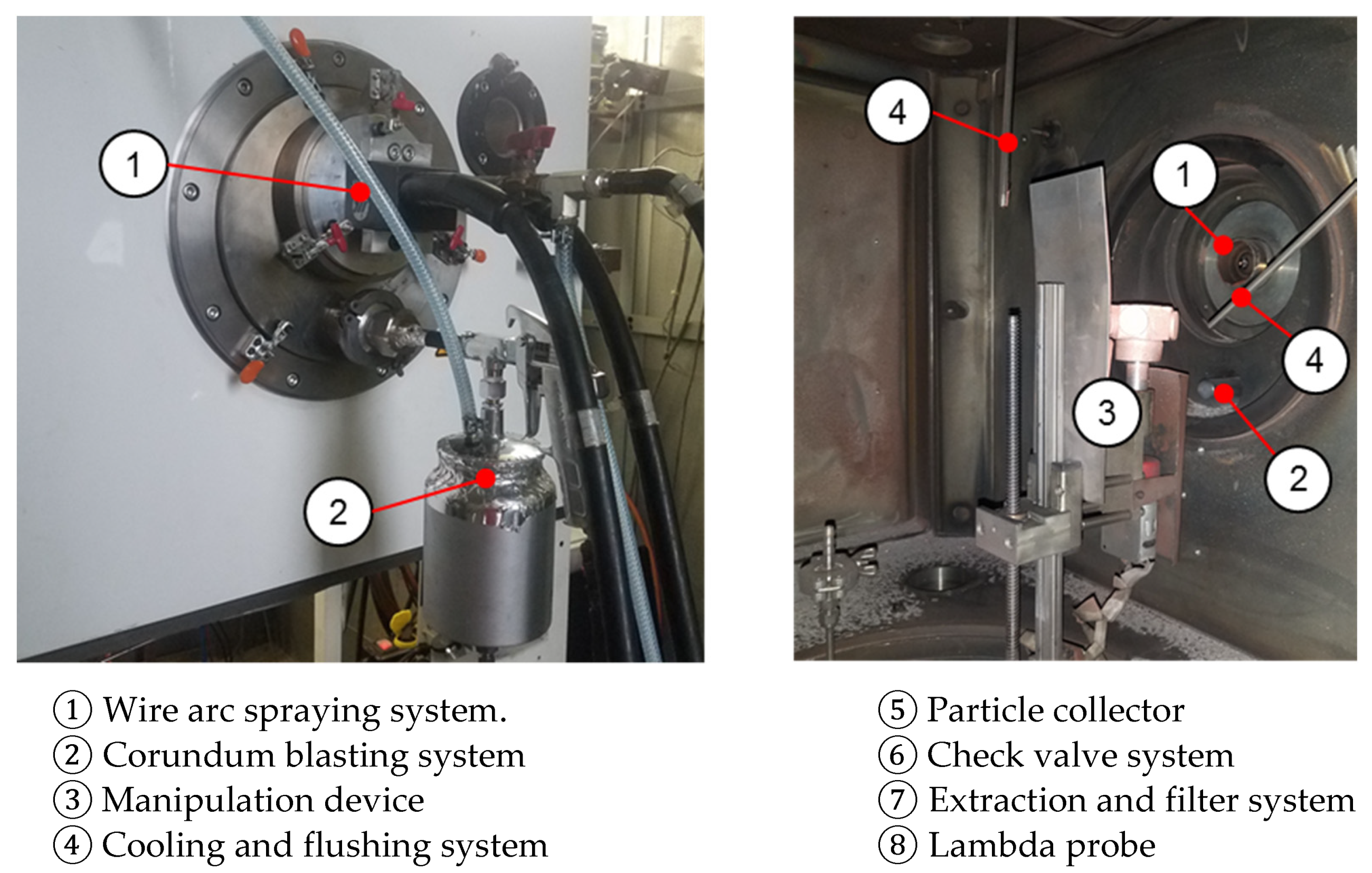
To perform the coating process in an oxygen-controlled environment, a 0.26 m3 custom-built coating chamber was used, with an integrated manipulation device and residual oxygen content monitoring system, as shown in Figure 1.
This coating chamber not only allowed the coating process to be carried out in a controlled environment, but also permitted the same environment for the corundum blasting process for surface activation. By blasting in the controlled environment, an oxide-free substrate-coating interface can be realized by suppressing the formation of a wetting-inhibiting native oxide film on the substrate surface. To create a blasting and coating environment with a residual oxygen concentration equivalent to the oxygen concentration of an extreme high vacuum (XHV), the coating chamber, corundum tank and conveying gas hoses were first flushed with commercial quality nitrogen. The residual oxygen content in this blasting and coating environment was around 10−4 vol.−% at ambient pressure. In the next step, the residual oxygen content was quantitatively converted into silicon dioxide (SiO2) and hydrogen by adding monosilane (SiH4) with a stoichiometric ratio according to the following conversion reaction:
SiH4 (g) + O2 (g) ⇌ SiO2 (s) + 2H2 (g)
SiH4 (g) + 2H2O (g) ⇌ SiO2 (s) + 4H2 (g)
As presented in [22], the formed silicon dioxide is amorphous, which is classified as non-toxic. This allowed for the establishment of a blasting and coating environment with a residual oxygen content of 10−26 vol.−% at the start of the process, corresponding to an oxygen content of ≈10−23 Pa.

2.2. Coating Method and Materials

Wire arc spraying was used as the coating process. It should be noted that the blasting and coating parameters were kept identical in the different process environments. With identical coating parameters, the differences in the coating properties can thus be attributed to the residual oxygen content of the environment due to the similarity of the physical properties of air and nitrogen. Table 1 summarizes the blasting and coating parameters and the used materials.

2.3. Characterisation of the Coating Morphology

The coating morphology was analysed using a reflected light microscopy analysis. Additionally, scanning electron microscopy (SEM) was performed on the coating surfaces using a Helios Nanolab 600 (FEI Germany GmbH, Frankfurt, Germany) with a dual-beam system operating under high vacuum conditions at a base pressure of 10−4 Pa. The porosity was determined by a digital analysis using the software ImageJ [23].

2.4. Young’s Modulus and Residual Stress Evaluation

In order to investigate the effect of the different environmental conditions on residual stresses, the hole-drilling strain-gage method was employed using the MTS3000-Restan residual stress analyser (SINT TECHNOLOGY S.R.L., Calenzano, Italy). Test and evaluation procedures were performed in accordance with the ASTM E837 standard using a 1.6 mm drill bit [24]. The evaluation was carried out using the power series method; this method is an approximation of the integral method [25]. The numerical coefficients used to calculate the residual stress values were according to those in the study by Schajer [26].
Prior to the characterisation of the mechanical properties, the surface roughness of the individual samples was observed using confocal laser microscopy (Keyence VK9700, Keyence Deutschland GmbH, Neu-Isenburg, Germany) with a magnification of 50× and step size of 0.1 µm. For this purpose, six areas were selected on each sample, and a projected area of 100 µm2 was measured.
To determine the residual stresses of the coatings, the apparent Young’s modulus is crucial. The mechanical properties of the coatings were characterised by means of nanoindentations using a Hysitron Triboindenter Ti 900 nanoindenter (Bruker, Minneapolis, MN, USA) with a possible force ranging from 2 µN to 10,000 µN. The characterisation was carried out with respect to the hardness (according to DIN EN ISO 14577-1) and Young’s modulus (according to Oliver and Pharr) using a 2D transducer and diamond Berkovich tip with a tip radius of 150 nm [27,28,29]. A force-controlled trapezoidal force-displacement function was used, which had an applied force for 5 s, a holding period for 2 s, and a release for 5 s, as according to [30,31]. Prior to the measurements, a calibration of the tip was carried out on fused quartz in a force range between 8000 μN and 10 μN in descending force, descending at 100 μN intervals with a drift rate of 0.031 nm/s. Afterwards, the tip area function was created [32]. To minimise the influence of high roughness, the 5% rule of thumb should be applied, where the surface roughness should not exceed 5% of the depth at which the results are needed [33]. Due to an average surface roughness Ra of above 8 µm, this rule could not be applied, and therefore the surface was initially scanned in order to find a suitable position for the indentations using the atomic force microscopy (AFM) mode of the Hysitron Triboindenter Ti 900 nanonindenter (according to DIN EN ISO 25178); it was performed in the horizontal scan orientation with a scan rate of 0.2 Hz and scan area of 200 µm2. Subsequently, the indents were placed at defined locations with lower roughness values (Ra < 40 nm) at a minimum distance of 2 µm. The indentation depth between 100 nm and 300 nm was achieved by setting the peak load levels to range from 1200 µN to 800 µN. The loading rate over the peak load was 50 µN s−1. For each peak load, 15 indentations were carried out at different locations on the specimen, with the force and indentation depth continuously recorded at a rate of 500 measurements per second during the process.

3. Results and Discussion

3.1. Coating Morphology

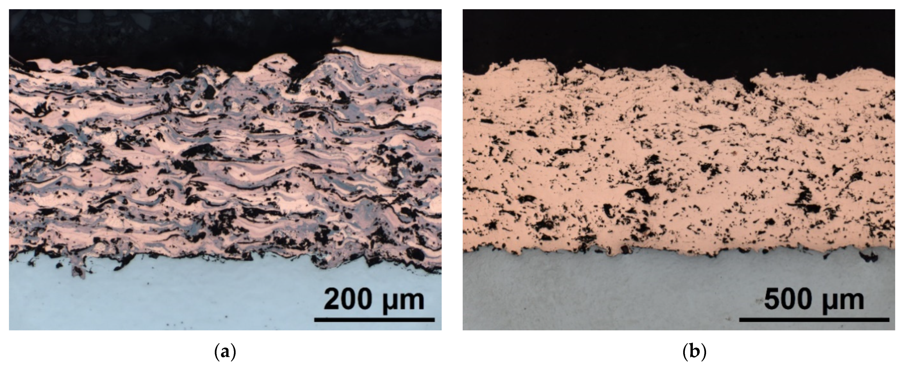
Figure 2 compares the reflected light microscopy images of the arc sprayed copper coatings produced in different process atmospheres. Figure 2a depicts the conventional arc sprayed copper coating produced in an air environment and using compressed air as the atomising gas. The typical coating morphology of an arc sprayed coating, with pronounced oxide fringes, is clearly visible. The porosity within the coating was determined to be approx. 18% using a digital image analysis. Figure 2b depicts a cross-section of an oxide-free copper coating produced in a silane-doped nitrogen environment using silane-doped nitrogen as the atomising gas. The applied coating reveals a substantially reduced porosity of approx. 5%. Moreover, no oxide seams are detectable. The homogenous coating morphology indicates that a material bond has formed between the individual splats.
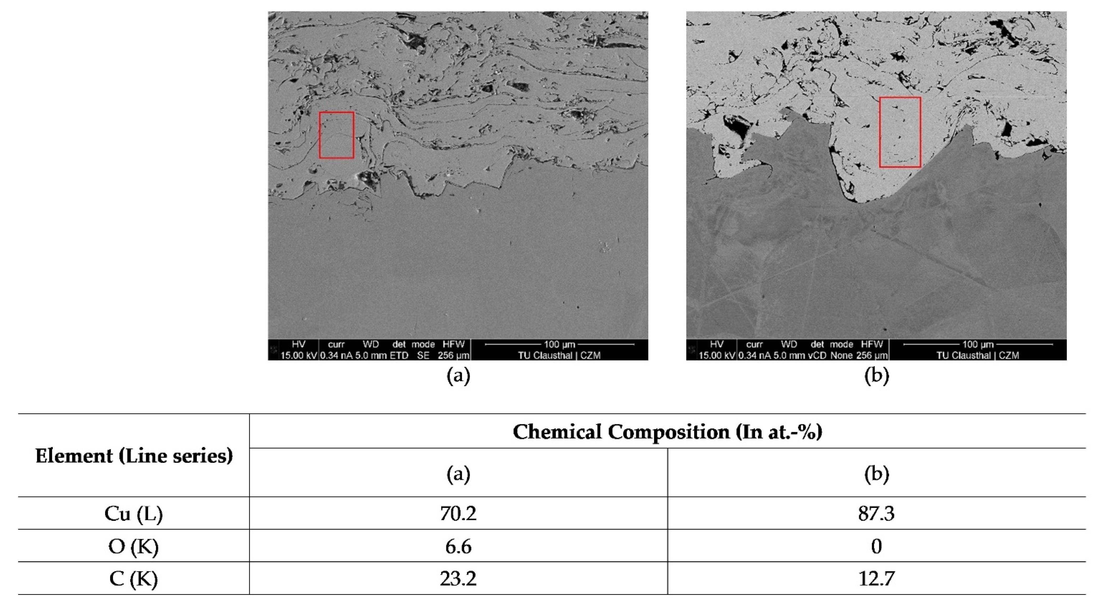
Figure 3 shows SEM images and a table of the chemical composition of the copper coatings blasted and coated in air vs. blasted and coated in silane-doped nitrogen. The chemical composition data were gathered via the energy dispersive spectroscopy (EDS) technique with a 15 kV acceleration voltage. The spots used for the EDS analysis are highlighted by red boxes.
The table in Figure 3 reveals that the copper coating produced in the silane-doped nitrogen environment shows an increased amount of copper by ≈17 at.−% and a decreased carbon and oxygen content in comparison to the coating produced in air. No oxygen is detected in the sample coated in the silane-doped nitrogen after the EDS measurement. These results support the statements that oxide-free coatings can be produced in silane-doped nitrogen atmospheres, as portrayed by Equation (1). The lower carbon content can be explained by a reduced amount of organic contaminants usually found within manufactured inert gases compared with oil-contaminated compressed air.
Figure 4 shows cross-sections from the substrate-coating interface to reveal the effect obtained by transferring not only the coating process to the oxygen-free environment, but also the corundum blasting process.
Figure 4b is a cross-section of the interface of a conventionally applied copper coating. Figure 4b is a cross-section of the interface of an oxide-free copper coating. In both cases, the substrate activation process was performed in an air atmosphere, using compressed air as the blasting gas. A clearly visible gap is detectable along the entire interface of these coatings. Figure 4c shows the interface of an oxide-free copper coating, where the surface activation process was carried out inside the custom-built process chamber at an oxygen content of 10−26 vol.−%. This coating has a significantly reduced interfacial gap, with full wetting of the substrate surface.
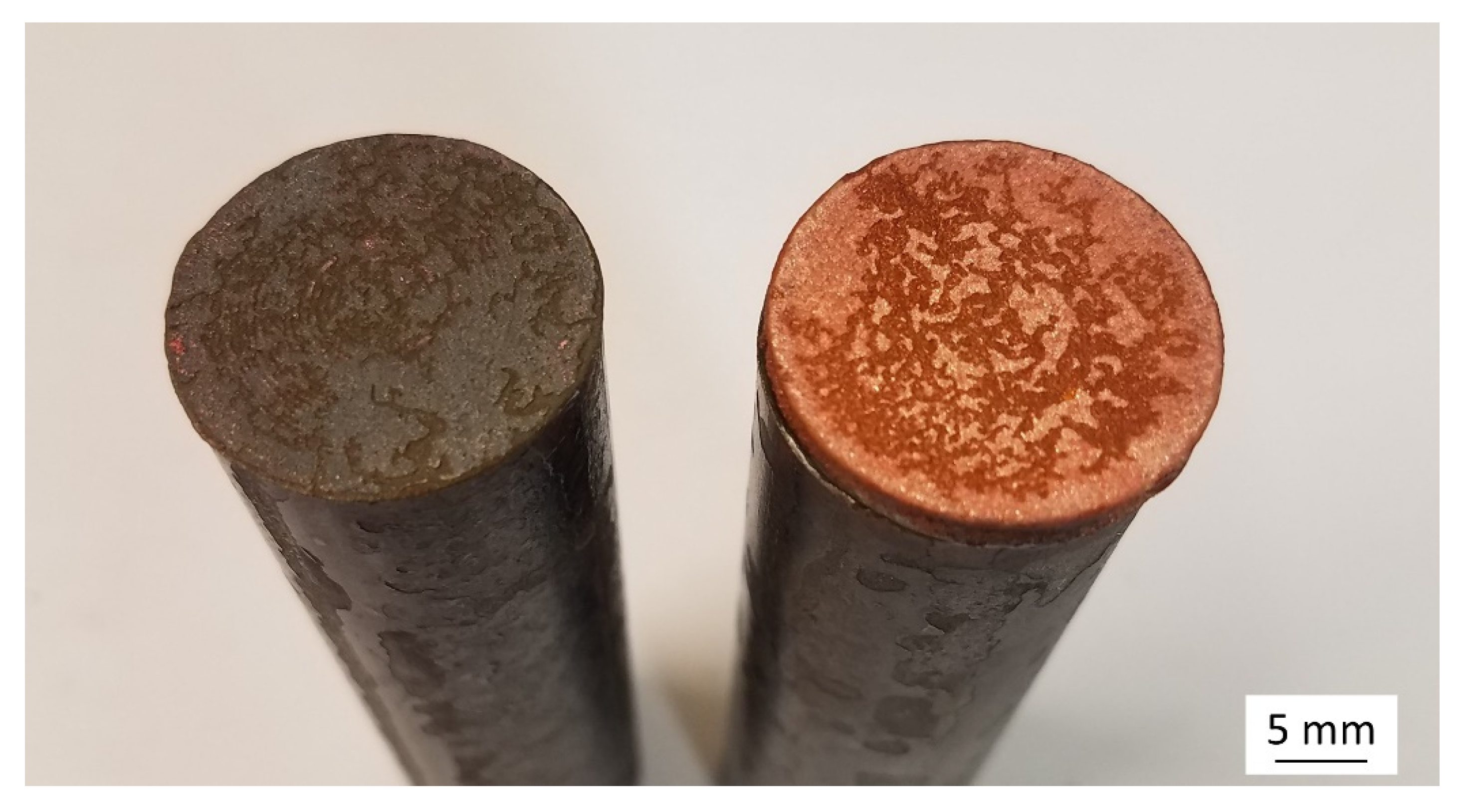
The investigation of the interface clearly shows the influence of the residual oxygen content in the environment during the surface activation process on the binding mechanisms of a thermally sprayed coating. A native oxide layer is formed if the blasting process takes place in air, which impairs the wetting behaviour of the impacting particles. Thus, due to the oxide film at the interface, even when an oxide-free coating is applied, the bonding mechanisms are still largely determined by the number of undercuts and mechanical interlocking of the particles. In this context, reference is made to the work of Gourlaouen et al. [34], where wire arc sprayed copper coatings were produced in air and in pure nitrogen. Despite that oxide-free copper coatings were reported, the oxide-free copper coatings did not show any improvements with regard to their adhesive tensile strength. Both the conventional and the oxide-free copper coatings achieved adhesive tensile strengths of 32.2 ± 4.7 MPa. Although not described in the paper, it can be assumed that the surface activation process was carried out conventionally in the presence of oxygen and that a wetting-inhibiting oxide layer was still present on the substrate. Furthermore, commercially available nitrogen contains too much residual oxygen to completely suppress oxidation processes during the coating process. Thus, the bonding mechanisms of the oxide-free copper coatings were still defined by the mechanical interlocking of the impacting particles, despite the creation of a copper coating with a reduced oxide content. As presented in Figure 4c, the formation of a wetting-inhibiting native oxide layer on the substrate surface can be suppressed by transferring the blasting process to an oxygen-free environment. This provides the prerequisite for the complete wetting of the substrate surface, resulting in a drastic increase in the adhesive tensile strengths, as shown in [21]. In that particular work, adhesion tensile strength tests according to the DIN EN ISO 14916 standard revealed strengths of 25.1 ± 0.4 MPa for copper coatings conventionally sprayed in air, with a strict cohesive coating failure. Copper coatings produced in a silane-doped nitrogen atmosphere (residual oxygen content: 10−26 vol.−%) but having the upstream surface activation process carried out conventionally in air achieved adhesive tensile strengths of 35 ± 2.4 MPa, which is in agreement with the results of Gourlaouen et al., with pure adhesive failure. For coatings blasted and coated in an oxygen-free environment, an adhesive tensile strength of 63.9 ± 3.0 MPa was achieved. The fracture occurred in this case due to a failure of the adhesive used (Ultrabond 100). Figure 5 shows one of the tested samples, indicating that the real maximum adhesive tensile strengths of the coatings might be even higher.

3.2. Particle Formation

The analysis of the coating morphologies showed that the processing under oxygen-free conditions has a significant influence on the wetting behaviour. Thus, conditions can be created that permit the splats to form a material bond with each other during the deposition process. Blasting under oxygen-free conditions also improves the wetting behaviour on the substrate surface to such an extent that the interfacial gaps are minimised and completely closed in most places. Although the improved wetting behaviour has a reducing effect on the resulting coating porosity, the coatings are not pore-free and by far do not reach the low porosities of, e.g., cold gas sprayed copper coatings [35,36,37]. In this context, the key factor is the altered particle formation.
In contrast to other coating processes such as atmospheric plasma spraying or cold gas spraying, where the size of the impacting particles is predetermined by the powder fractionation used, particle formation in the arc spraying method is a complex process. According to [38,39,40], the breakup behaviour of a molten droplet in a free jet during arc spraying can be described by the dimensionless Weber number:
We = (ρg × v2 × Dp)/σ
where ρg is the atomising gas density in kg/m3, Dp is the droplet diameter in m, v is the relative atomising gas velocity in m/s, and σ is the surface tension of the molten droplet in kg/s2. This shows that the atomisation of a molten droplet in a gas jet also depends on the surface tension σ of the particles, and thus on the occurrence of surface tension affecting the oxide film. The analysis of particles atomised with silane-doped nitrogen showed that the absence of oxygen led to a significant change in the atomisation behaviour. The primary particles were atomised into much smaller particles than with the conventional arc spraying in an air atmosphere. These small particles could be detected both in and on the surface of the coating, as shown in Figure 6.
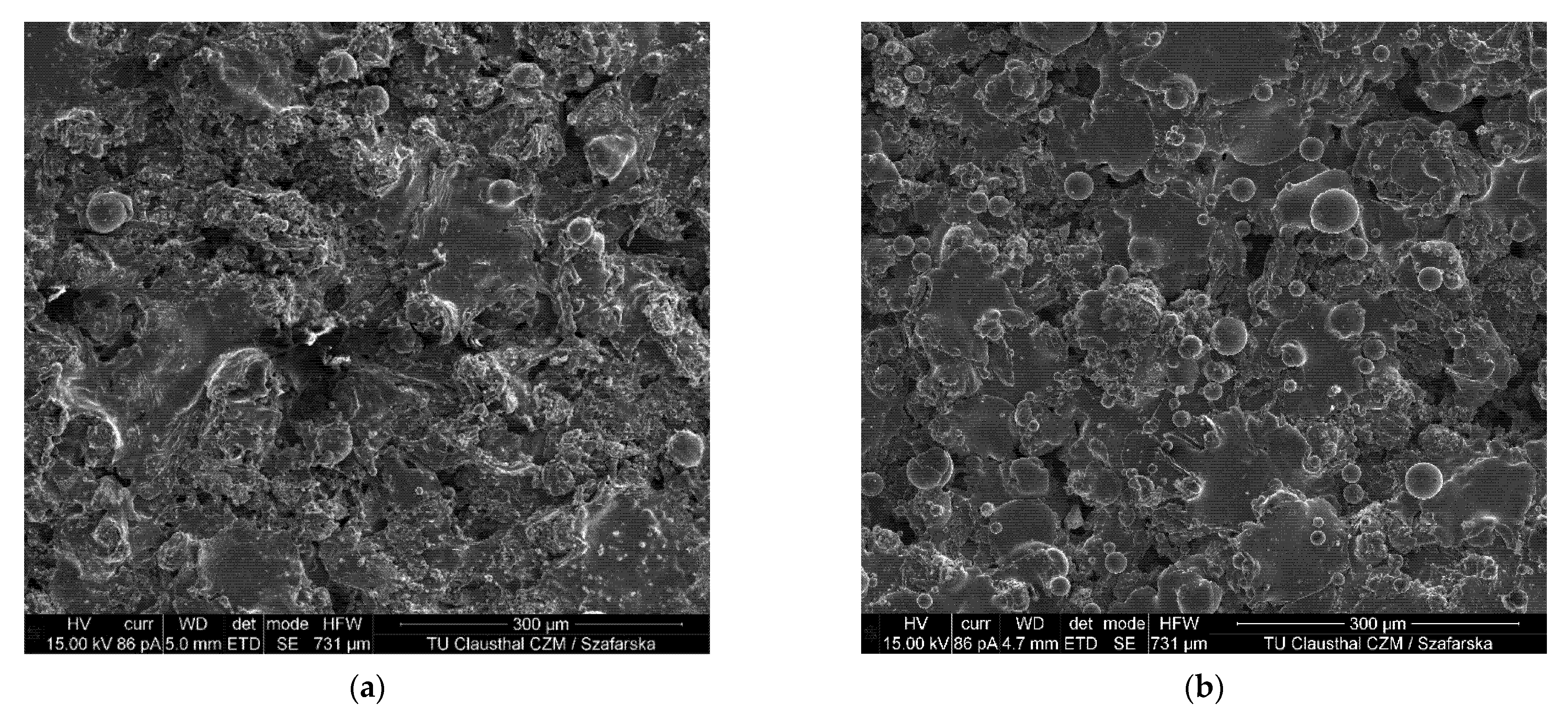
Compared to the coatings produced in air, the oxide-free coatings have considerably smaller particles on the coating surface (cf. Figure 6). However, considering the corresponding smoother splat shapes, this has no significant influence on the resulting coating surface roughness, as presented in Table 2.
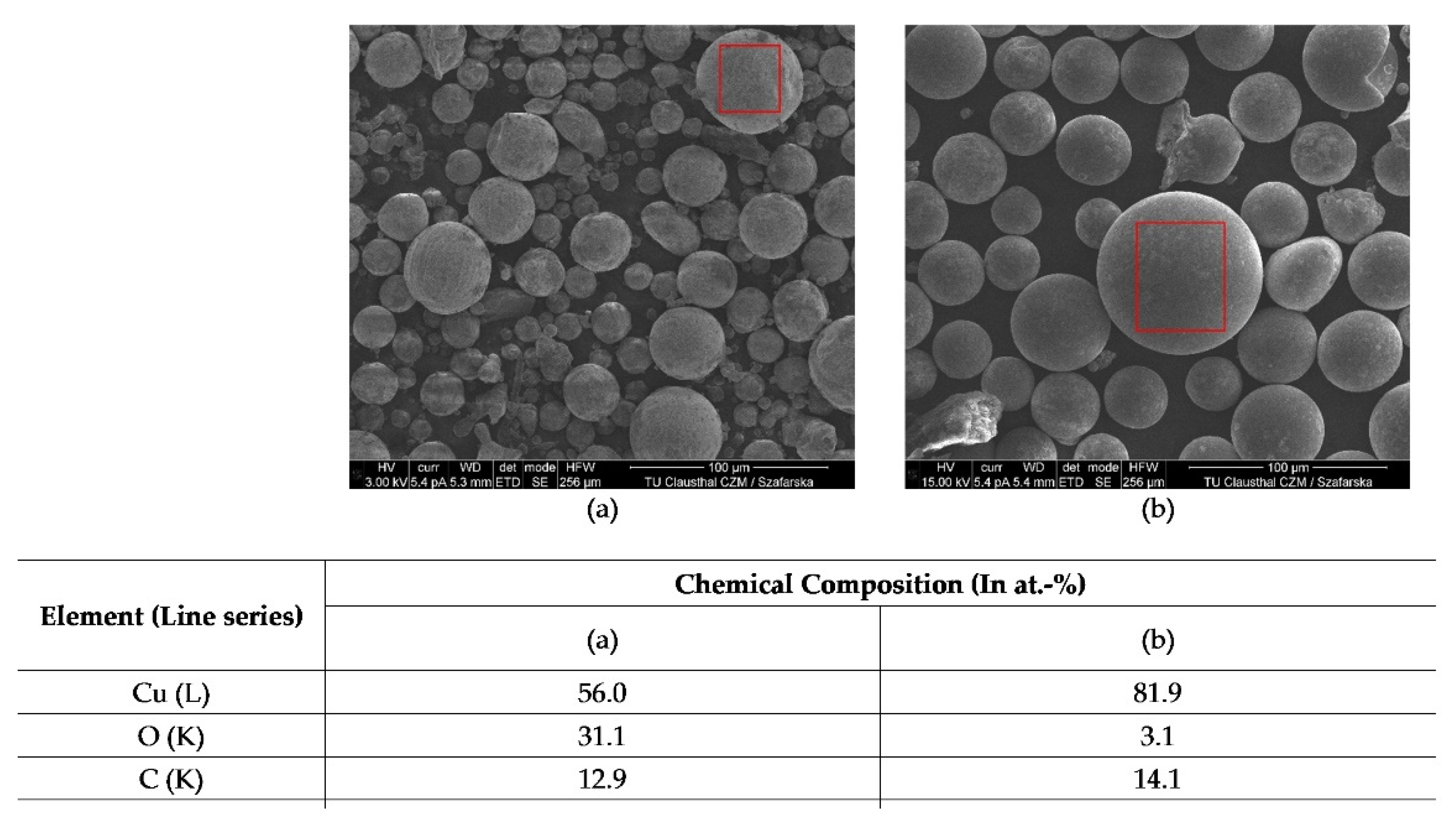
Figure 7 depicts SEM images and the chemical composition of copper particles cre-ated by atomization in air and in silane-doped nitrogen. The data of chemical composi-tion were gathered via EDS with 15 kV acceleration voltage. The spots used for analysis are highlighted by red boxes.
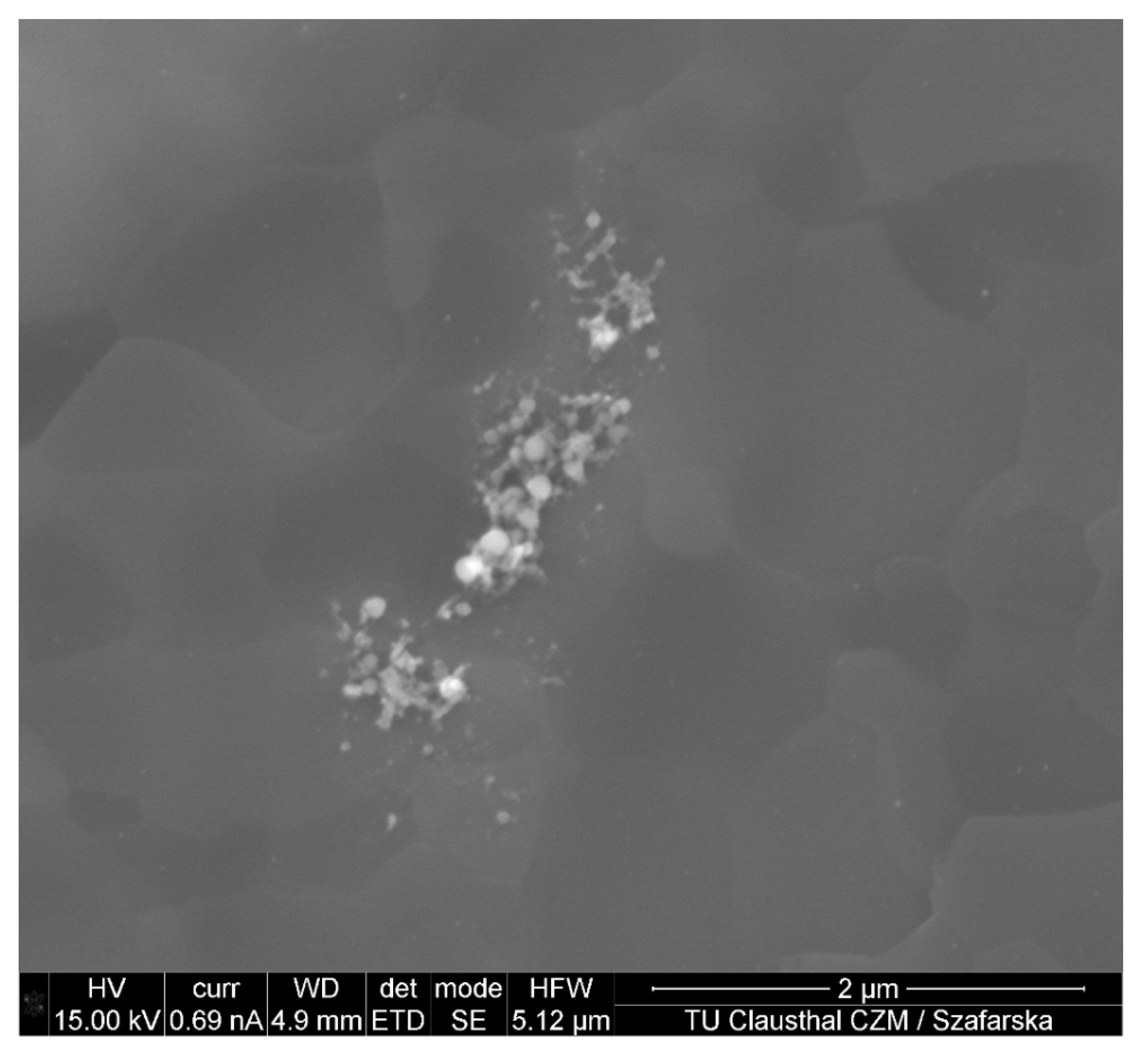
As presented in the table of Figure 7, the relative atomic percentage of copper found in the particles created in silane-doped nitrogen is 25.9% higher than in air. The oxygen content significantly drops by 28 at.−%, from 31.1 at.−% down to 3.1 at.−%. The reaction between silane and oxygen is most likely responsible for this observation. Because most molecular oxygen is removed before coating, there is practically no oxygen left to cause the oxidation of the copper particles. Moreover, as a small amount of silicon is present, some of the remaining oxygen found can be attributed to SiO2, as shown in Figure 8.
The EDS analysis of the coatings and particles also reveals the origin of the SiO2. Because the SiO2 is only detected on the coatings [21] and particles but not within the coatings (cf. Figure 3), its formation is mostly due to the reaction between the residual silane in the coating environment and the oxygen in the ambient atmosphere when opening the coating chamber after the coating process.

3.3. Apparent Young’s Modulus

The mean values from the nanoindentation results of the coatings blasted and coated in air showed an apparent Young’s modulus of 67.1 ± 5.8 GPa, while the coatings blasted and coated in silane-doped nitrogen revealed a significant increase, almost doubling the elastic modulus to 123.7 ± 21.2 GPa.
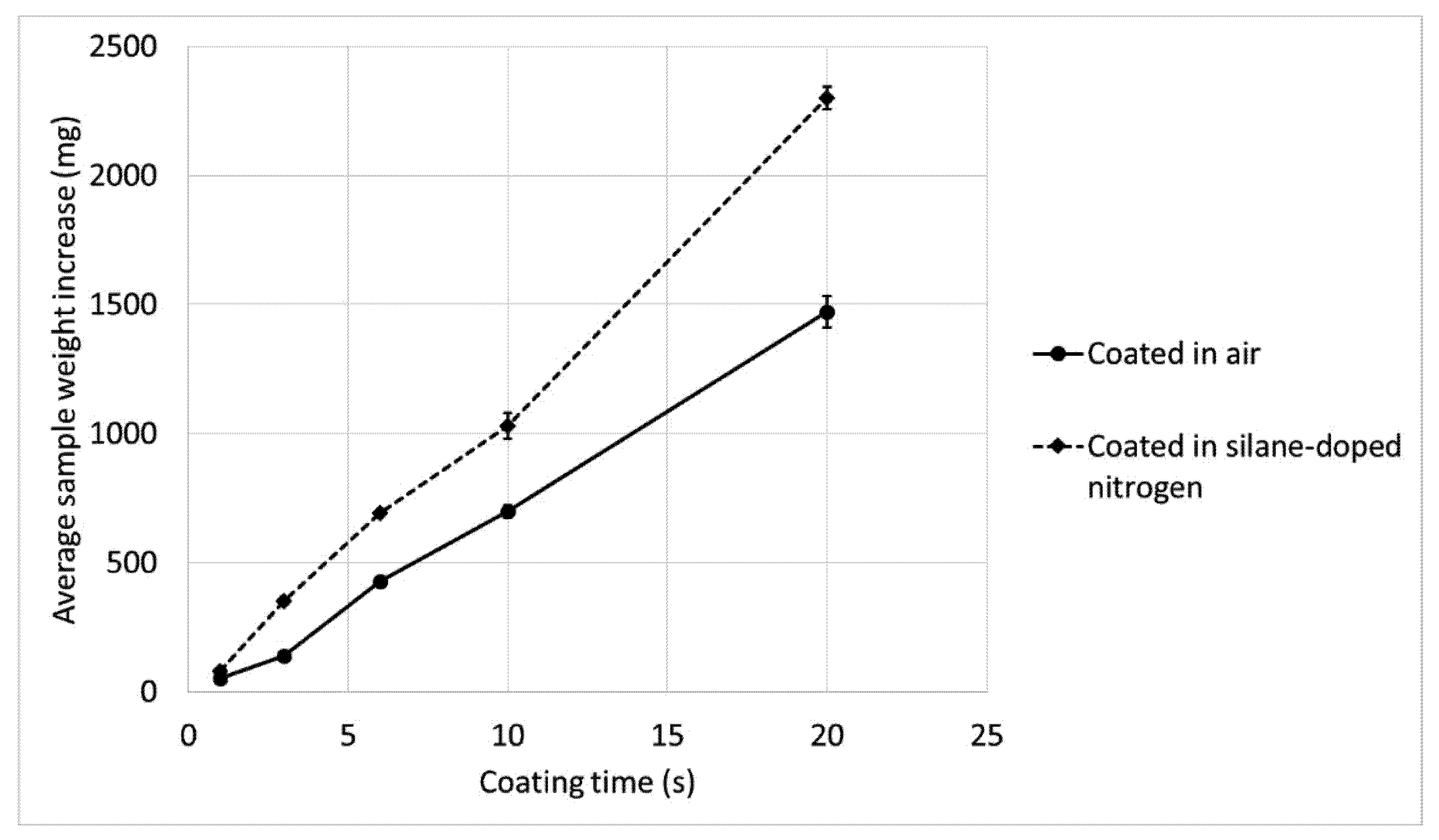
The apparent Young’s modulus of a coating depends on the particle temperature (higher temperature means lower apparent Young’s modulus), bonding rate (higher bonding rate means higher apparent Young’s modulus), and porosity (higher porosity and cavities mean lower apparent Young’s modulus) [2,41]. Due to the design of the custom-built coating chamber, the integration of a particle diagnostic system to analyse the particle temperature was not possible. However, based on the work of Abkenar, which measured the particle temperature during arc spraying in air and nitrogen during the flight phase, it can be assumed that the temperature of the copper particles in silane-doped nitrogen is marginally lower than in air [39]. With regard to the correlation of bonding rate and apparent Young‘s modulus, the coating ratio on the conventional air blasted samples was determined in different coating environments and coating times. To ensure statistical reliability, four 25 mm discs were coated simultaneously for each coating test, and their mean values were determined. The following Figure 9 presents the average sample weight increase versus coating time, which were the data used to determine the average coating ratio.
Clear differences can already be observed due to the coating environment after a coating time of one second. The samples coated in air have an average weight increase of 51.5 ± 2.3 mg, while the samples coated in silane-doped nitrogen have an average weight increase of 79.3 ± 3.1 mg. This corresponds to a 55% higher coating ratio in the oxide-free coatings compared with the coatings formed in air. This is explained by the improved wetting behaviour of the oxide-free copper particles on the substrate surface. With an increasing coating duration, the average coating ratio of both coating systems improved due to the change in the coating time-dependent temperature regime of the samples. Thus, after 20 s, the samples coated in air show an average coating ratio of ≈73.6 mg/s, resulting in an average weight increase of 1471 ± 60.3 mg. In contrast, the coatings applied in silane-doped nitrogen have a resulting average coating ratio of ≈115.1 mg/s, which was determined by the average weight increase of 2301 ± 44.1 mg. This corresponds to an average bonding rate increase of 56.5% compared with the conventional air coatings. Considering the resulting coating ratio and the previously presented reduction in coating porosity (cf. Section 3.1), an increased Young‘s modulus in the oxide-free coatings is plausible.

3.4. Residual Stresses

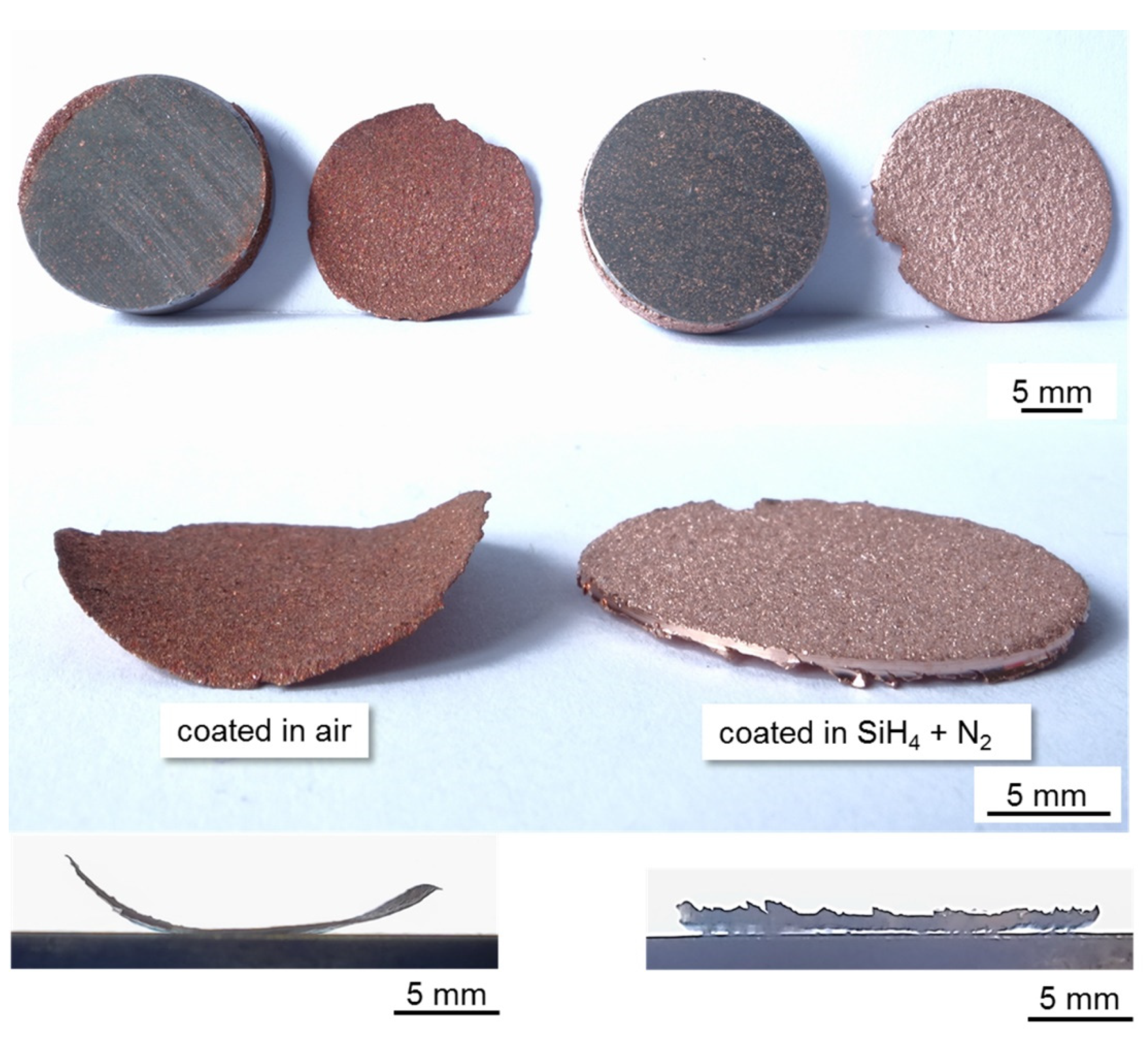
Residual stresses have a significant impact on the adhesion of thermally sprayed coatings [42,43,44]. In order to evaluate their possible influences on the adhesive tensile strengths and evaluate the failure mechanisms presented in [21], we determined the residual stresses of both the conventional and oxide-free coatings. A simple but effective way to qualitatively determine residual stresses in thermally sprayed coatings is to measure the curvature of the released coating. An essential process step during the coating process is corundum blasting for surface activation. This involves a roughening of the surface to ensure that there are sufficient undercuts on the substrate surface for the mechanical interlocking of the coating. Applying a thermally sprayed coating to a non-blasted surface will inevitably result in the residual leading to delamination, and thus coating spallation [1,2,42]. The samples (Ø 20 mm, 1.0038) used for the analysis of the residual stresses were ultrasonically cleaned after cutting and then coated with the parameters shown in Table 1; this was performed for both the conventional air and with silane-doped nitrogen samples. The corresponding results are presented in Figure 10.
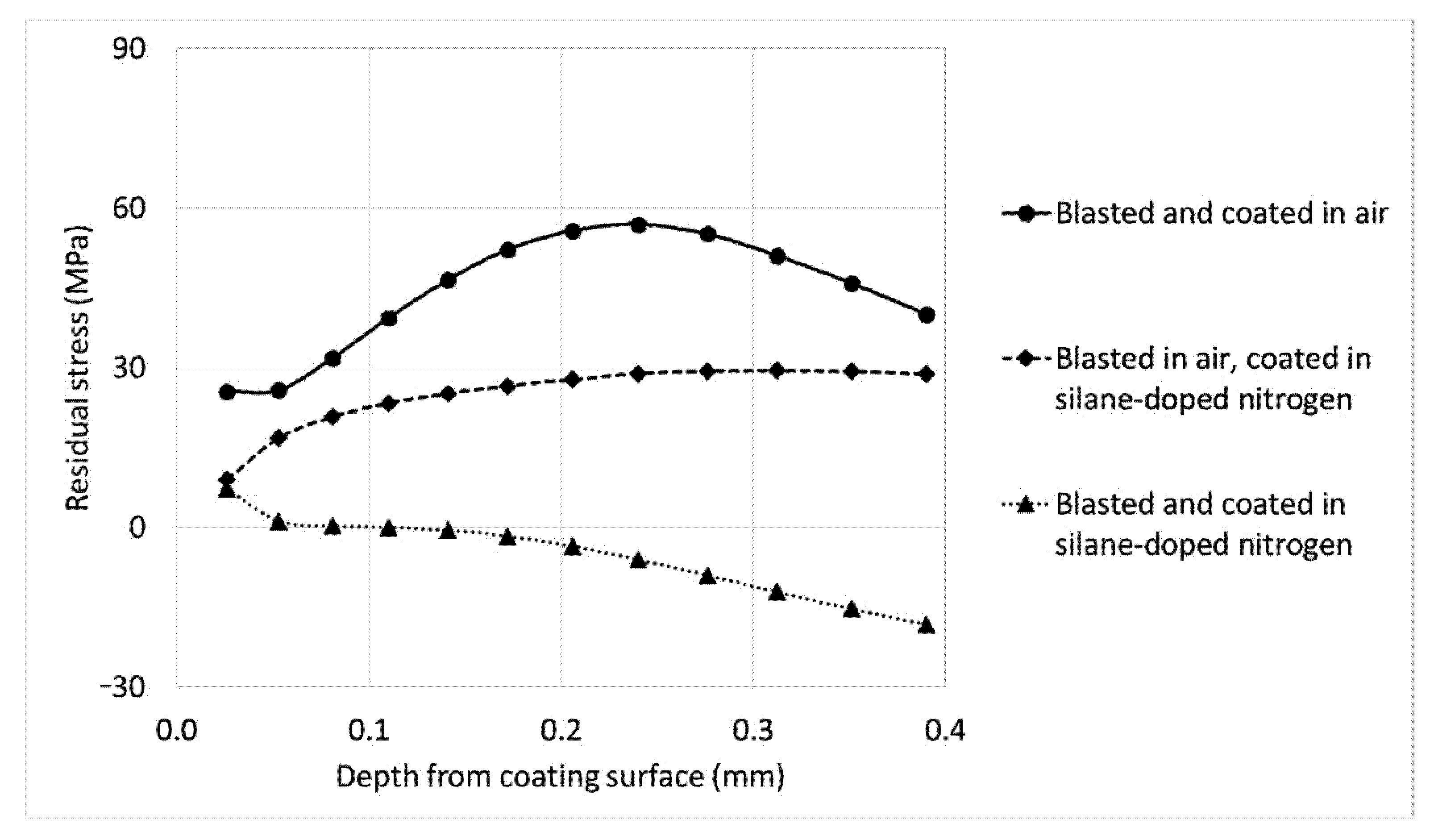
In the case of the oxide-containing coatings, the residual stresses had already led to coating failure during the first coating cycle. The coatings reached a maximum thickness of ≈100 µm. The measured curvature radius was ≈9 mm, which is an indicator of high residual quenching stresses within the coatings. In contrast, the coatings produced in silane-doped nitrogen did not fail even after four complete coating cycles and had a total coating thickness of ≈750 µm. Thus, although the coatings were mechanically removed, no significant curvature of the coating was detected. In addition to the improved bonding between the individual splats and the coating on the substrate, this example would be a further explanation for the substantially increased adhesive tensile strengths presented in [21]. Furthermore, this also explains why the samples blasted and coated in silane-doped nitrogen show pure adhesive failure without coating failure at the edges of the coating, as sharp transitions are the weak point of any thermally sprayed coating [1,2]. Additionally, in order to obtain quantitative information about the prevailing residual stresses, we examined coatings of ≈400 µm thickness on 25 mm discs using the hole-drilling strain-gage method. The results are summarised in Figure 11.
The hole-drilling strain-gage measurements showed significantly lower and less varying residual stresses for the coatings produced in silane-doped nitrogen than for those produced in air. The copper coating that was conventionally produced in air features a maximum tensile stress of 57 MPa. In contrast, the sample produced in the oxygen-free environment but activated in air had a maximum tensile stress of 29 MPa. When comparing the results of the measurements with respect to the blasting environment, the influence of the improved wetting of the particles on the stress curve over the coating depth also becomes apparent. The sample blasted and coated in silane-doped nitrogen possessed compressive stresses of 17 MPa at the interface. Due to the enhanced bonding to the substrate, the peening effect on the substrate surface by the grit blasting clearly affects the residual stress distribution within the coating.
The results obtained demonstrate that the effects on the residual stresses in the coatings become apparent upon moving to a truly oxygen-free environment. For instance, Clyne and Gill described that there were no significant differences in the residual stresses of conventional and vacuum sprayed coatings [2,43]. It has also been reported that a direct correlation exists between the apparent Young’s modulus of the coating and the residual stresses: the higher the apparent Young‘s modulus, the higher the residual stresses due to inhibition of possible relaxation mechanisms [2,42,45,46,47]. Thus, solely based on the Young’s modulus presented in Section 3.3., the oxide-free coatings should have higher residual stresses than the oxide-containing coatings. However, the residual stress state in the entire coating/substrate system is determined by the superposition of different types of stress induced during the spraying process [2,45,48,49,50]. These are the superpositioning of quenching, peening, and thermal mismatch stresses. However, the residual stresses are largely attributed to the shrinkage of the impacting particles, which lead to tensile quenching stresses within the coatings [51,52]. The actual quenching stress values depend on the contact ratio of the splats and relaxation phenomena. As possible relaxation phenomena microcrack formation, through thickness yielding, interfacial sliding, creeping and edge relaxation are reported [2,53,54].
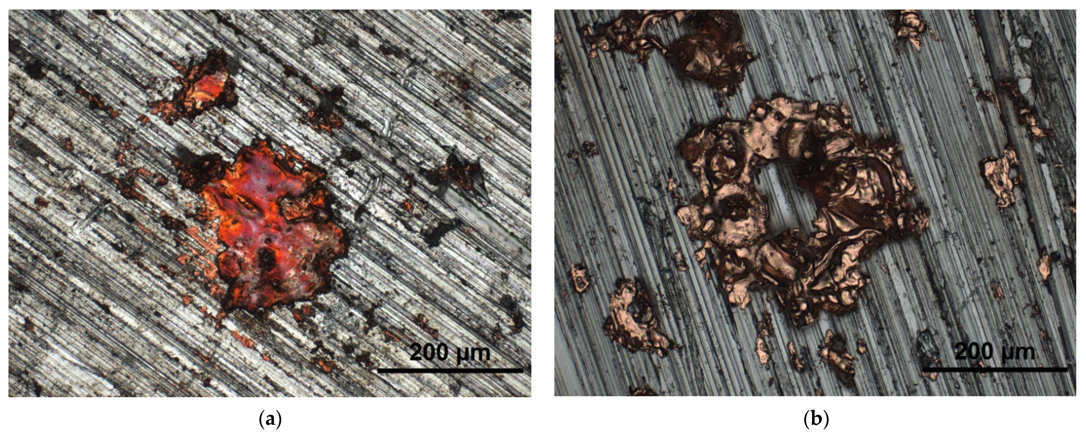
In fact, the splashing of fully melted particles upon impact drastically affect the coating properties [2,55,56]. Thus, we investigated the dispersion behaviour of the particles. This involved the investigation of the dispersion behaviour at two interfaces: the splat/substrate surface and splat/previously deposited layer interface. Figure 12 shows the spreading behaviour of copper particles on a non-blasted substrate surface in different environments.
While the splats formed in air have the typical pancake shape (Figure 12a), the oxide-free splats have a doughnut shape (Figure 12b). According to the results obtained from the literature, this effect can be attributed to the temperature gradient at the interface [57,58,59,60]. Wilden and Frank showed using a simulation that at the same substrate temperature, particle size, and particle velocity, but at an increased particle temperature, the pancake-like spreading behaviour can be expected to change to the doughnut-shaped spreading [58]. Similarly, Yang et al. were able to attribute the formation of the doughnut-shaped splats to a preheating of the substrate [59]. Assuming that the particle temperatures in silane-doped nitrogen are marginally lower than in air [61], the doughnut-like spreading behaviour upon spraying in silane-doped nitrogen is attributed to the absence of an oxide film on the surface of the particles, which led to an enhanced heat transfer and dispersion behaviour. By contrast, the increased surface tension of the oxide-containing particles reduces the wetting and heat transfer behaviour, which in turn causes a transition to a pancake-shaped splat form.
In this context, Tillmann et al. showed the influence of different splat forms on the residual stresses at the interface. By varying the spray angle, the splat spreading behaviour was significantly influenced. By decreasing the coating angle, the impacting splats increasingly deviated from the typical pancake shape, resulting in significantly lower tensile residual stresses at the interface [62]. In this case, a reduction of the quenching stresses by higher peening stresses can be excluded, as the compressive stresses decrease by reducing the coating angle [2]. Consequently, it is reasonable to assume that the deviation from the typical pancake shape has a significant influence on the stress field within the individual splats at the coating/substrate surface interface.
When considering the spreading behaviour of the splats on the coating surface, it is obvious that the oxide-free splats now also exhibit the typical pancake-like spreading behaviour, although they are flatter than the splats formed in air, cf. Figure 13. The lack of a wetting-inhibiting oxide film also influences the wetting and spreading behaviour as well as the heat transfer to the previously applied splat layer. This in turn results in a smaller wetting angle and thus flatter splats. Furthermore, it reduces the number of interfacial gaps and coating porosity which, according to the presented results in Section 3.3 and in various studies, has a high impact on the apparent Young’s modulus [41,62].
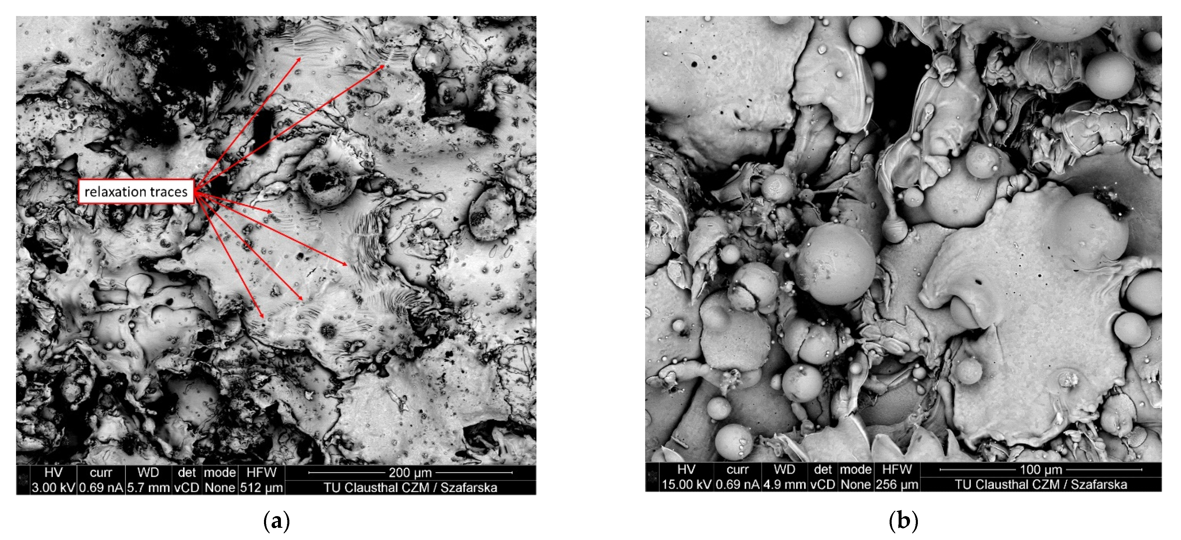
As previously mentioned, the study showed that coatings with decreasing coating porosity and an increased bonding ratio have a higher apparent Young‘s modulus, and thus higher residual stresses as the relaxation is curtailed. In this context, the splats were examined for relaxation traces, cf. Figure 14.
As can be clearly seen in the Figure 14a, the copper splats formed in air feature relaxation traces not only at the splat edges, but also to a lower extent in the centre of the splats, while the oxide-free splats do not exhibit these traces, cf. Figure 14b. However, this contradicts the determined residual stresses. Conversely, the effect of porosity and bonding rate on thermal conductivity has also been reported: As the porosity decreases and bonding rate increases, the thermal conductivity increases [2,63]. This influence on the temperature–time regime appears to have greater effects on the dispersion and relaxation mechanisms of the particles than expected. Some studies have shown that changes in the temperature–time regime during relaxation have an important impact on the resulting residual stresses. Effects such as those reported by post-weld or post-coating heat treatment cannot be excluded [64,65], as well as the influence of altered cooling speeds on residual stresses [66]. The works by Shrestha et al. and Yañez et al. demonstrate that a heat treatment of thermally sprayed coatings promotes relaxation mechanisms and reduces residual stresses [67,68]. Preheating the substrate also significantly affects the resulting residual stresses. The works of Tillmann et al. and Oukach et al. describe the influence of substrate preheating on the residual stresses; by preheating the substrate surface, the temperature gradient in the composite system could be reduced, resulting in a lower temperature change over the coating time. Composite systems that did not experience any temperature increase or decrease during the coating process showed lower and more consistently distributed residual stresses over the coating thickness [62,69]. Thus, it can be assumed that the oxide-free transition presented in Figure 4c increases the thermal conductivity, resulting in a more homogeneous temperature distribution during the coating process within the composite system, affecting the residual stresses. Moreover, the change in heat transfer not only affects the temperature distribution within the composite, but also affects the cooling rate and speed. Another aspect that is largely not considered in thermal spraying but could have a decisive impact on the residual stresses is the possible influence of the tribological load on the underside of the splats, which could occur when sliding across the oxide-covered interface gap during the spreading, shrinking, and relaxing stages. The complete wetting of the oxide-free transitions at the interface do not allow for relative movements at the interface. In contrast, the relative movements over the roughness peaks caused by the oxide-containing interface transition could provide for residual stress induction, similar to the residual stress induction in grinding processes [70].

4. Conclusions

In order to evaluate possible influences on the adhesive tensile strengths and failure mechanisms of oxide-free wire arc sprayed copper coatings, the coating morphology, Young’s modulus, and residual stresses of both conventional and oxide-free copper coatings were compared and analysed. The main results can be summarised as follows:
  • It is possible to generate an XHV-adequate coating atmosphere using silane-doped nitrogen as the coating atmosphere and atomisation gas; thus, this method establishes the conditions needed for the formation of a material bond within thermally sprayed coatings.
  • An enhanced wetting behaviour on the substrate surface is possible by conducting the surface activation process in a silane-doped inert gas environment. In this environment, new process conditions and effects can be observed: the particle formation, atomisation, and dispersion behaviour are significantly different, which have a decisive effect on the resulting coating morphology and properties.
  • Due to the suppression of a wetting-inhibiting oxide film forming on the copper particles, the coatings produced in a silane-doped nitrogen atmosphere are free of oxide seams, exhibiting a significantly reduced coating porosity that ranges from 18% to 5%.
  • The transfer to an oxygen-free environment led to a 56% increase in the coating ratio, resulting in an increase in the apparent Young’s modulus.
  • Interestingly, although the apparent Young‘s modulus is significantly increased and almost doubles the modulus of the coatings applied in air, meaning that the relaxation mechanisms should be curtailed, the coatings produced in the XHV-adequate atmosphere feature substantially lower residual stresses than the conventionally sprayed coatings. The extent to which the absence of an oxide film in the atomised particles and the altered particle size distribution influence the temperature–time regime, splat formation, apparent Young’s modulus, and thus the residual stresses, is the subject of current investigations.

Author Contributions

Conceptualisation, M.R.D., S.R., M.C.W., M.S., R.G., K.M. and H.J.M.; methodology, M.R.D.; software, M.R.D., S.R. and M.S.; validation, M.R.D., S.R. and M.S.; formal analysis, M.R.D., S.R. and M.S.; investigation, M.R.D., S.R. and M.S.; resources, M.C.W., R.G., K.M. and H.J.M.; data curation, M.R.D., S.R. and M.S.; writing—original draft preparation, M.R.D.; writing—review and editing, M.R.D., S.R., M.C.W., M.S., R.G., K.M. and H.J.M.; visualisation, M.R.D. and M.S.; supervision, M.C.W., R.G., K.M. and H.J.M.; project administration, M.C.W., R.G., K.M. and H.J.M.; funding acquisition, M.C.W., R.G., K.M. and H.J.M. All authors have read and agreed to the published version of the manuscript.

Funding

This project is funded by the Deutsche Forschungsgemeinschaft (DFG, German Research Foundation), Project-ID 394563137–SFB 1368.

Institutional Review Board Statement

Not applicable.

Informed Consent Statement

Not applicable.

Data Availability Statement

The data presented in this study are available upon request from the corresponding author.

Acknowledgments

The authors thank André Langohr and Sabine Friederichs for the metallurgical sample preparation and Uwe Dix for the hole-drilling strain-gage measurements.

Conflicts of Interest

The authors declare no conflict of interest.

References

  1. Lugscheider, E. (Ed.) Handbuch Der Thermischen Spritztechnik: Technologien—Werkstoffe—Fertigung. In Deutscher Verband für Schweißen und Verwandte Verfahren; DVS-Verlag: Düsseldorf, Germany, 2001; ISBN 978-3-87155-186-4. (In German) [Google Scholar]
  2. Heberlein, J.V.R. Thermal Spray Fundamentals: From Powder to Part, 1st ed.; Springer: New York, NY, USA, 2014; ISBN 978-0-387-68991-3. [Google Scholar]
  3. Davis, J.R. (Ed.) Handbook of Thermal Spray Technology: Introduction to Thermal Spray Processing; ASM International: Novelty, OH, USA, 2004; ISBN 9780871707956. [Google Scholar]
  4. Planche, M.P.; Liao, H.; Coddet, C. Oxidation Control in Atmospheric Plasma Spraying Coating. Surf. Coat. Technol. 2007, 202, 69–76. [Google Scholar] [CrossRef]
  5. Matthews, S. Development of High Carbide Dissolution/Low Carbon Loss Cr3C2–Nicr Coatings by Shrouded Plasma Spraying. Surf. Coat. Technol. 2014, 258, 886–900. [Google Scholar] [CrossRef]
  6. Gattinoni, C.; Michaelides, A. Atomistic Details of Oxide Surfaces and Surface Oxidation: The Example of Copper and Its Oxides. Surf. Sci. Rep. 2015, 70, 424–447. [Google Scholar] [CrossRef] [Green Version]
  7. Bach, F.-W.; Möhwald, K.; Laarmann, A.; Wenz, T. (Eds.) Moderne Beschichtungsverfahren; Wiley-VCH: Weinheim, Germany, 2005; ISBN 978-3-527-30977-1. (In German) [Google Scholar]
  8. Metco, O. An Introduction to Thermal Spray. 2016. Available online: https://www.oerlikon.com/ecoma/files/BRO-0005.6_Thermal_Spray_Brochure_EN.pdf (accessed on 31 January 2022).
  9. Odhiambo, J.G.; Li, W.; Zhao, Y.; Li, C. Porosity and Its Significance in Plasma-Sprayed Coatings. Coatings 2019, 9, 460. [Google Scholar] [CrossRef] [Green Version]
  10. Da Silva, F.S.; Cinca, N.; Dosta, S.; Cano, I.G.; Guilemany, J.M.; Caires, C.S.A.; Lima, A.R.; Silva, C.M.; Oliveira, S.L.; Caires, A.R.L.; et al. Corrosion Resistance and Antibacterial Properties of Copper Coating Deposited by Cold Gas Spray. Surf. Coat. Technol. 2019, 361, 292–301. [Google Scholar] [CrossRef]
  11. Gärtner, F.; Stoltenhoff, T.; Voyer, J.; Kreye, H.; Riekehr, S.; Koçak, M. Mechanical Properties of Cold-Sprayed and Thermally Sprayed Copper Coatings. Surf. Coat. Technol. 2006, 200, 6770–6782. [Google Scholar] [CrossRef]
  12. Champagne, V.K. The Cold Spray Materials Deposition Process: Fundamentals and Applications; Woodhead: Cambridge, MA, USA, 2007; ISBN 978-1-84569-181-3. [Google Scholar]
  13. Assadi, H.; Gärtner, F.; Stoltenhoff, T.; Kreye, H. Bonding Mechanism in Cold Gas Spraying. Acta Mater. 2003, 51, 4379–4394. [Google Scholar] [CrossRef]
  14. Gillet, V.; Aubignat, E.; Costil, S.; Courant, B.; Langlade, C.; Casari, P.; Knapp, W.; Planche, M.P. Development of Low Pressure Cold Sprayed Copper Coatings on Carbon Fiber Reinforced Polymer (Cfrp). Surf. Coat. Technol. 2019, 364, 306–316. [Google Scholar] [CrossRef]
  15. Villafuerte, J. (Ed.) Modern Cold Spray: Materials, Process, and Applications, 1st ed.; Springer: Cham, Switzerland, 2015. [Google Scholar] [CrossRef]
  16. Smith, M.F.; Hall, A.C.; Fleetwood, J.D.; Meyer, P. Very Low Pressure Plasma Spray—A Review of an Emerging Technology in the Thermal Spray Community. Coatings 2011, 1, 117–132. [Google Scholar] [CrossRef]
  17. Matthews, S. Shrouded Plasma Spray of Ni–20Cr Coatings Utilizing Internal Shroud Film Cooling. Surf. Coat. Technol. 2014, 249, 56–74. [Google Scholar] [CrossRef]
  18. Wang, X.; Heberlein, J.; Pfender, E.; Gerberich, W. Effect of Nozzle Configuration, Gas Pressure, and Gas Type on Coating Properties in Wire Arc Spray. J. Therm. Spray Technol. 1999, 8, 565–575. [Google Scholar] [CrossRef]
  19. Niu, Y.; Lu, D.; Huang, L.; Zhao, J.; Zheng, X.; Chen, G. Comparison of W–Cu Composite Coatings Fabricated by Atmospheric and Vacuum Plasma Spray Processes. Vacuum 2015, 117, 98–103. [Google Scholar] [CrossRef]
  20. Holländer, U.; Wulff, D.; Langohr, A.; Möhwald, K.; Maier, H.J. Brazing in Sih4-Doped Inert Gases: A New Approach to an Environment Friendly Production Process. Int. J. Precis. Eng. Manuf.-Green Tech. 2020, 7, 1059–1071. [Google Scholar] [CrossRef] [Green Version]
  21. Diaz, M.R.; Szafarska, M.; Gustus, R.; Möhwald, K.; Maier, H.J. Oxide Free Wire Arc Sprayed Coatings—An Avenue to Enhanced Adhesive Tensile Strength. Metals 2022, 12, 684. [Google Scholar] [CrossRef]
  22. Diaz, M.R.; Nicolaus, M.; Möhwald, K.; Maier, H.J. Thermal Spraying in Silane-Doped Shielding Gases: A New Approach for Innovative Coatings in Controlled Process Atmospheres. Therm. Spray Bull. 2021, 14, 120–127. [Google Scholar]
  23. Broeke, J.M.M.P.J. Image Processing with Imagej, 2nd ed.; Packt Publishing Limited: Birmingham, UK, 2015; ISBN 9781785881589. [Google Scholar]
  24. E28 Committee. Test Method for Determining Residual Stresses by the Hole-Drilling Strain-Gage Method; E28 Committee: West Conshohocken, PA, USA. [CrossRef]
  25. SINT Technology, s.r.l. Restan: Messsystem zur Bestimmung von Eigenspannungen nach der Bohrlochmethode Messsystem zur Bestimmung von Eigenspannungen nach der Bohrlochmethode, Calenzano, Florenz, Italy, Calenzano, Florenz, Italy. Available online: https://docplayer.org/9582377-Messsystem-zur-bestimmung-von-eigenspannungen-nach-der-bohrlochmethode-messsystem-zur-bestimmung-von-eigenspannungen-nach-der-bohrlochmethode.html (accessed on 8 September 2022). (In German).
  26. Schajer, G.S. Application of Finite Element Calculations to Residual Stress Measurements. J. Eng. Mater. Technol. 1981, 103, 157–163. [Google Scholar] [CrossRef]
  27. Din En Iso 4287:2010-07; Geometrische Produktspezifikation (Gps) Oberflächenbeschaffenheit: Tastschnittverfahren- Benennungen, Definitionen Und Kenngrößen Der Oberflächenbeschaffenheit (Iso 4287:1997 + Cor 1:1998 + Cor 2:2005 + Amd 1:2009); Deutsche Fassung En Iso 4287:1998 + Ac:2008 + A1:2009. Beuth-Verlag: Berlin, Germany, 2010. (In German) [CrossRef]
  28. Oliver, W.C.; Pharr, G.M. An Improved Technique for Determining Hardness and Elastic Modulus Using Load and Displacement Sensing Indentation Experiments. J. Mater. Res. 1992, 7, 1564–1583. [Google Scholar] [CrossRef]
  29. Din En Iso 14577-1:2015-11; Metallische Werkstoffe—Instrumentierte Eindringprüfung Zur Bestimmung Der Härte Und Anderer Werkstoffparameter—Teil 1: Prüfverfahren (Iso_14577-1:2015), Deutsche Fassung En_Iso_14577-1:2015. Beuth: Berlin, Germany, 2015. (In German) [CrossRef]
  30. Oyen, M.L.; Cook, R.F. Load–Displacement Behavior During Sharp Indentation of Viscous–Elastic–Plastic Materials. J. Mater. Res. 2003, 18, 139–150. [Google Scholar] [CrossRef]
  31. Dean, J.; Wheeler, J.M.; Clyne, T.W. Use of Quasi-Static Nanoindentation Data to Obtain Stress–Strain Characteristics for Metallic Materials. Acta Mater. 2010, 58, 3613–3623. [Google Scholar] [CrossRef]
  32. Frederick, F.L.; Winer, W.O.; Bergles, A.E.; Klutke, G.A.; Wang, K.K.; Finnie, I.; Welty, J.R.; Bryant, M.D.; Yang, H.T.; Mow, V.C.; et al. Nanoindentation; Springer: New York, NY, USA, 2011. [Google Scholar] [CrossRef]
  33. Hay, J.L.; Pharr, G.M. Instrumented Indentation Testing, Mechanical Testing and Evaluation; Kuhn, H., Medlin, D., Eds.; ASM International: Novelty, OH, USA, 2000; pp. 232–243. [Google Scholar] [CrossRef] [Green Version]
  34. Gourlaouen, V.; Verna, E.; Beaubien, P. Enhanced Copper Coating Properties Obtained by Electric Wire Arc Spraying Process. In Thermal Spray 2010: Global Solutions for Future Applications; Marple, B.R., Agarwal, A., Hyland, M.M., Lau, Y.-C., Li, C.-J., Lima, R.S., Montavon, G., Eds.; Springer: Singapore, 2010; Volume 378, pp. 685–690. [Google Scholar] [CrossRef]
  35. Fernández, R.; MacDonald, D.; Nastić, A.; Jodoin, B.; Tieu, A.; Vijay, M. Enhancement and Prediction of Adhesion Strength of Copper Cold Spray Coatings on Steel Substrates for Nuclear Fuel Repository. J. Therm. Spray Technol. 2016, 25, 1577–1587. [Google Scholar] [CrossRef]
  36. Hussain, T.; McCartney, D.G.; Shipway, P.H.; Zhang, D. Bonding Mechanisms in Cold Spraying: The Contributions of Metallurgical and Mechanical Components. J. Therm. Spray Technol. 2009, 18, 364–379. [Google Scholar] [CrossRef]
  37. Váz, R.F.; Silvello, A.; Cavalière, P.D.; Dosta, S.; Cano, I.G.; Capodieci, L.; Rizzo, A.; Valerini, D. Fretting Wear and Scratch Resistance of Cold-Sprayed Pure Cu and Ti. Metallogr. Microstruct. Anal. 2021, 10, 496–513. [Google Scholar] [CrossRef]
  38. Yule, A.J.; Dunkley, J.J. Atomization of Melts: For Powder Production and Spray Deposition; Clarendon Press: Oxford, UK, 1994; ISBN 10-0198562586. [Google Scholar]
  39. Abkenar, A.H.P. Wire-Arc Spraying System: Particle Production, Transport, and Deposition; Library and Archives Canada = Bibliothèque et Archives Canada: Ottawa, ON, Canada, 2007; ISBN 9780494397237. [Google Scholar]
  40. Wang, J.; Wang, Y.; Liu, J.; Zhang, L.; Gao, L.; Zheng, G.; Shen, H.; Sun, J. Microstructure and Flight Behaviors of Droplet and Its Solidification in Twin-Wire Arc Sprayed Ni-Al Composite Coatings. Mat. Res. 2018, 21, 26. [Google Scholar] [CrossRef]
  41. Li, C.-J.; Ohmori, A. Relationships Between the Microstructure and Properties of Thermally Sprayed Deposits. J. Therm. Spray Technol. 2002, 11, 365–374. [Google Scholar] [CrossRef]
  42. Araujo, P.; Chicot, D.; Staia, M.; Lesage, J. Residual Stresses and Adhesion of Thermal Spray Coatings. Surf. Eng. 2005, 21, 35–40. [Google Scholar] [CrossRef]
  43. Clyne, T.W.; Gill, S.C. Residual Stresses in Thermal Spray Coatings and Their Effect on Interfacial Adhesion: A Review of Recent Work. J. Therm. Spray Technol. 1996, 5, 401–418. [Google Scholar] [CrossRef]
  44. Kuroda, S.; Fukushima, T.; Kitahara, S. Significance of Quenching Stress in the Cohesion and Adhesion of Thermally Sprayed Coatings. J. Therm. Spray Technol. 1992, 1, 325–332. [Google Scholar] [CrossRef]
  45. Qu, Z.; He, R.; Fang, D. Stress among the Aps-Prepared Tbcs: Testing and Analysis, Methods for Film Synthesis and Coating Procedures; Nánai, L., Samantara, A., Fábián, L., Ratha, S., Eds.; IntechOpen: London, UK, 2020. [Google Scholar] [CrossRef] [Green Version]
  46. Sampath, S.; Jiang, X.Y.; Matejicek, J.; Prchlik, L.; Kulkarni, A.; Vaidya, A. Role of Thermal Spray Processing Method on the Microstructure, Residual Stress and Properties of Coatings: An Integrated Study for Ni–5 Wt.%Al Bond Coats. Mater. Sci. Eng. A 2004, 364, 216–231. [Google Scholar] [CrossRef]
  47. Chen, Q.; Mao, W.; Zhou, Y.; Lu, C. Effect of Young’s modulus evolution on residual stress measurement of thermal barrier coatings by X-ray diffraction. Appl. Surf. Sci. 2010, 256, 7311–7315. [Google Scholar] [CrossRef] [Green Version]
  48. Lyphout, C.; Nylén, P.; Manescu, A.; Pirling, T. Residual Stresses Distribution Through Thick Hvof Sprayed Inconel 718 Coatings. J. Therm. Spray Technol. 2008, 17, 915–923. [Google Scholar] [CrossRef]
  49. Luzin, V.; Kuroda, S.; Yin, S.; Ang, A. Advanced Residual Stress Analysis in Thermal Spray and Cold Spray Processes. J. Therm. Spray Technol. 2020, 29, 1211–1217. [Google Scholar] [CrossRef]
  50. AAng, S.M.; Berndt, C.C. A Review of Testing Methods for Thermal Spray Coatings. Int. Mater. Rev. 2014, 59, 179–223. [Google Scholar] [CrossRef]
  51. Tillmann, W.; Abdulgader, M.; Hüning, S. Der Einfluss Von Eigenspannungen in 100Cr6 Auf Die Mittels Hochgeschwindigkeitsflammspritzen (Hvof) Erzeugten Wc-Co Schichten. Shaker: Maastricht, Germany, 2019. (In German) [Google Scholar] [CrossRef]
  52. Tian, H.; Wang, C.; Guo, M.; Tang, Z.; Tong, H.; Wang, X.; Wei, S.; Xu, B. A Residual Stresses Numerical Simulation and the Relevant Thermal-Mechanical Mapping Relationship of Fe-Based Coatings. Results Phys. 2019, 13, 102195. [Google Scholar] [CrossRef]
  53. Mutter, M.G. Herstellung Thermisch Gespritzter Schichten Mit Optimierten Spannungseigenschaften; Verlag Forschungszentrum Jülich GmbH: Zentralbibliothek, Germany, 2016; ISBN 978-3-95806-200-9. (In German) [Google Scholar]
  54. Kuroda, S.; Clyne, T.W. The Quenching Stress in Thermally Sprayed Coatings. Thin Solid Film. 1991, 200, 49–66. [Google Scholar] [CrossRef]
  55. Pasandideh-Fard, M.; Pershin, V.; Chandra, S.; Mostaghimi, J. Splat Shapes in a Thermal Spray Coating Process: Simulations and Experiments. J. Therm. Spray Technol. 2002, 11, 206–217. [Google Scholar] [CrossRef]
  56. Oki, S. Relationship Between Splat Morphology and Property of Plasma Sprayed Alumina. Coatings 2004, 449–452, 925–928. [Google Scholar] [CrossRef]
  57. Liu, H.; Lavernia, E.J.; Rangel, R.H. Numerical Simulation of Substrate Impact and Freezing of Droplets in Plasma Spray Processes. Int. Mater. Rev. 1993, 26, 1900–1908. [Google Scholar] [CrossRef]
  58. Lugscheider, E. (Ed.) Thermal Spraying—Simulation of Coating Structure. In Thermal Spray 2005: Thermal Spray Connects: Explore Its Surfacing Potential! Lugscheider, E. (Ed.) DVS-German Welding Society: Basel, Switzerland, 2005; ISBN 978-3-87155-793-4. [Google Scholar]
  59. Yang, K.; Liu, M.; Zhou, K.; Deng, C. Recent Developments in the Research of Splat Formation Process in Thermal Spraying. J. Mater. 2013, 2013, 260758. [Google Scholar] [CrossRef] [PubMed] [Green Version]
  60. Cedelle, J.; Vardelle, M.; Fauchais, P. Influence of Stainless Steel Substrate Preheating on Surface Topography and on Millimeter- and Micrometer-Sized Splat Formation. Surf. Coat. Technol. 2006, 201, 1373–1382. [Google Scholar] [CrossRef]
  61. Abkenar, A.P. Wire-Arc Spraying System: Particle production, transport, and deposition. Ph.D. Thesis, University of Toronto, Library and Archives Canada, Ottawa, Canada, 2009. [Google Scholar]
  62. Tillmann, W.; Hagen, L.; Luo, W. Process Parameter Settings and Their Effect on Residual Stresses in Wc/W2c Reinforced Iron-Based Arc Sprayed Coatings. Coatings 2017, 7, 125. [Google Scholar] [CrossRef] [Green Version]
  63. Wang, Z.; Kulkarni, A.; Deshpande, S.; Nakamura, T.; Herman, H. Effects of Pores and Interfaces on Effective Properties of Plasma Sprayed Zirconia Coatings. Acta Mater. 2003, 51, 5319–5334. [Google Scholar] [CrossRef]
  64. Sharifi, H.; Raisi, S.; Tayebi, M. The effect of stress relieving treatment on mechanical properties and microstructure of different welding areas of A517 steel. Mater. Res. Express 2017, 4, 126508. [Google Scholar] [CrossRef]
  65. Sun, W.; Adrian, W.-Y.T.; Kaiqiang, W.; Shuo, Y.; Xiawei, Y.; Marinescu, I.; Liu, E. Post-Process Treatments on Supersonic Cold Sprayed Coatings: A Review. Coatings 2020, 10, 123. [Google Scholar] [CrossRef] [Green Version]
  66. Biswajit, D.; Muvvala, G.; Ashish, K.N.; Bandyopadhyay, P.P. Effect of cooling rate on residual stress and mechanical properties of laser remelted ceramic coating. J. Eur. Ceram. Soc. 2018, 38, 3932–3944. [Google Scholar] [CrossRef]
  67. Shrestha, D.; Azarmi, F.; Tangpong, X.W. Effect of Heat Treatment on Residual Stress of Cold Sprayed Nickel-Based Superalloys. J. Therm. Spray Technol. 2022, 31, 197–205. [Google Scholar] [CrossRef]
  68. Contreras, P.Y.; Sánchez, J.D.O.B.; Salas, C.A.P.; Flores, J.M.M.; García, A.L.G.; López, I.D. Study of the evolution of the residual stress state in thermal barrier coatings sprayed on AISI 304 stainless steel. DYNA 2016, 83, 159. [Google Scholar] [CrossRef]
  69. Oukach, S.; Hamdi, H.; el Ganaoui, M.; Pateyron, B. Thermo-Mechanical Simulation of Residual Stresses in Plasma Sprayed Coatings. Appl. J. Environ. Eng. Sci. 2018, 4, 270–281. [Google Scholar] [CrossRef]
  70. Zhang, Z.; Sui, M.; Li, C.; Chang, Z.; Zongming, L.; Bo, C.; Yun, S.; Zafar, D.; Sujan, S. Residual stress of grinding cemented carbide using MoS2 nano-lubricant. Int. J. Adv. Manuf. Technol. 2022, 119, 5671–5685. [Google Scholar] [CrossRef]
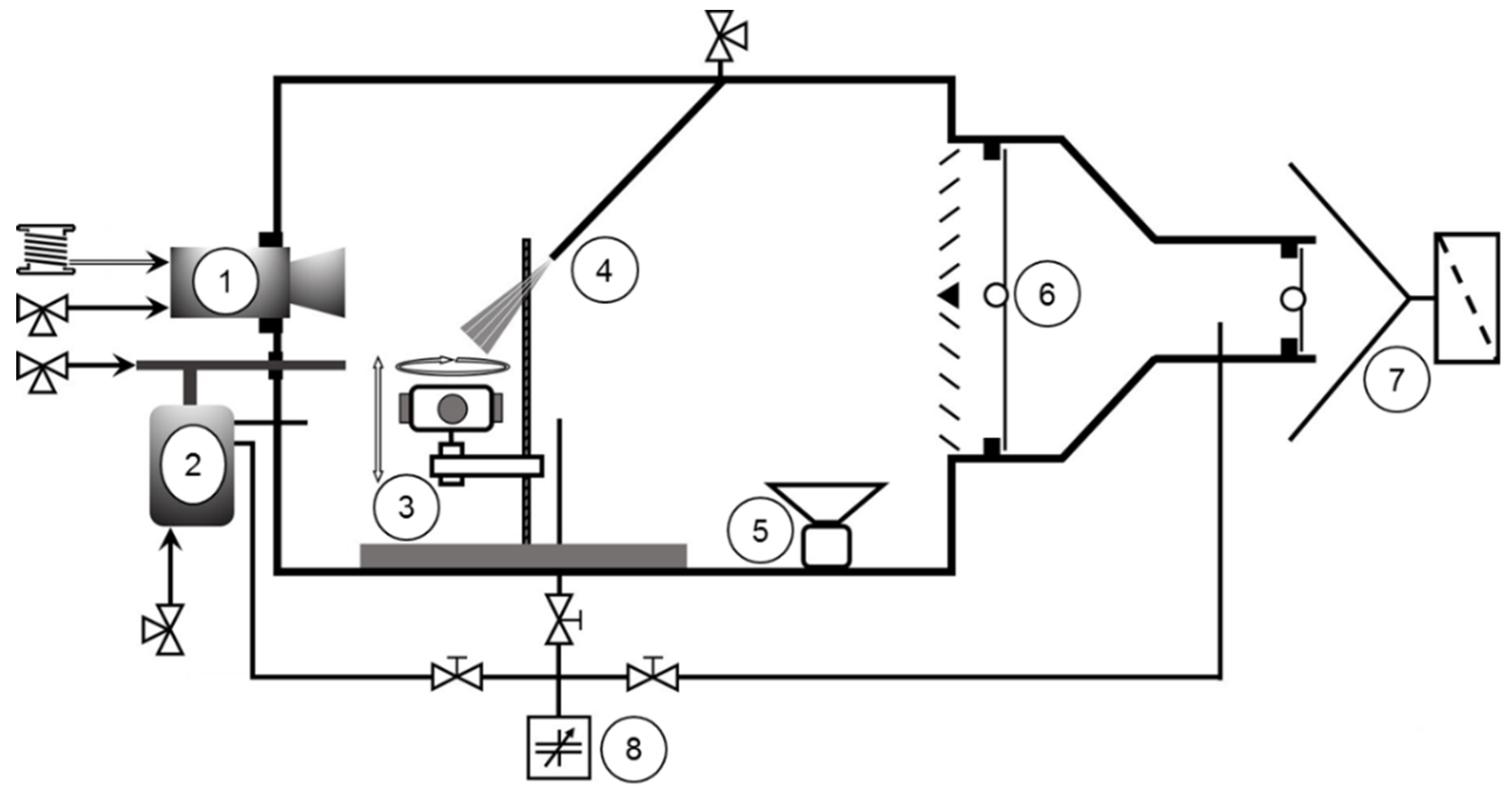
Figure 1. Custom-built process chamber with an attached blasting and twin wire arc coating system [21].
Coatings 12 01482 g001aCoatings 12 01482 g001b
Figure 2. Optical micrographs obtained on cross-sections that depict the microstructures of the wire arc sprayed copper coatings applied in different environments: (a) conventional process in air; and (b) process with silane-doped nitrogen.
Coatings 12 01482 g002
Figure 3. SEM images of cross-sections of copper coatings with their corresponding chemical composition: (a) blasted and sprayed in air; and (b) blasted and sprayed in silane-doped nitrogen.
Coatings 12 01482 g003
Figure 4. Optical micrographs revealing the interfacial gaps of wire arc copper coatings: (a) conventionally processed, i.e., blasted and sprayed in air; (b) blasted in air, sprayed in silane-doped nitrogen; and (c) blasted and sprayed in silane-doped nitrogen.
Coatings 12 01482 g004
Figure 5. Representative adhesive tensile stamp with adhesive failure after a tensile strength test.
Coatings 12 01482 g005
Figure 6. Trapped micro particles (a) in a copper coating and (b) on the copper coating surface when produced in an oxygen-free environment; (c) coating surface of a conventional copper coating.
Coatings 12 01482 g006
Figure 7. SEM images and the chemical composition of the copper particles created by atomisation in air and in silane-doped nitrogen. The chemical composition data were gathered via an EDS analysis with a 15 kV acceleration voltage. The spots used for analysis are highlighted by red boxes.
Coatings 12 01482 g007
Figure 8. SEM image of SiO2 agglomerates on a copper particle atomised in silane-doped nitrogen.
Coatings 12 01482 g008
Figure 9. Average sample weight increase versus coating time in the application of wire arc sprayed copper coatings in different coating environments.
Coatings 12 01482 g009
Figure 10. Optical images showing the substantial variation in the residual stress-induced curvature of the differently sprayed copper coatings.
Coatings 12 01482 g010
Figure 11. Residual stress within wire arc sprayed copper coatings.
Coatings 12 01482 g011
Figure 12. Optical micrographs revealing the shape of the splats formed on the substrate surface in different environments: (a) copper splats formed in air; and (b) copper splats formed in silane-doped nitrogen.
Coatings 12 01482 g012
Figure 13. SEM images of the copper coating surfaces: (a) copper coating formed in air and (b) formed in silane-doped nitrogen.
Coatings 12 01482 g013
Figure 14. SEM images of representative copper splats on the coating surface: (a) formed in air, featuring relaxation traces, and (b) formed in silane-doped nitrogen.
Coatings 12 01482 g014
Table 1. Process parameters used for the blasting and wire arc spraying processes.
Blasting Parameters
Blasting gun
(Conventional blasting in air)
Goldmann Spezial 1000
Blasting gun
(Blasting in controlled environment)
Schneider SSP-SAV
Blasting materialEKF 36
Blasting distance90 mm
Blasting angle90°
Blasting overruns6 at 1 m/s
Conveying gasAirSiH4 + N2 (≈10−23 Pa)
Conveying gas pressure800 kPa
Environment gasAirSiH4 + N2 (≈10−23 Pa)
Wire Arc Spraying Parameters
GunMiller BP400 (Modularc 400R)
Coating materialTwin copper wire, Ø1.6 mm, GTV 50.12.
Atomisation gasAirSiH4 + N2 (≈10−23 Pa)
Atomisation gas rate90 m³/h
Environment gasAirSiH4 + N2, (≈10−23 Pa)
Relative coating velocity1 m/s
Current100 A
Voltage30 V
Resulting wire feed rate≈130 g/min
Coating distance100 mm
Substrate
MaterialSteel discs
Material number1.0038
Chemical compositionCMnPSNCu
0.171.40.0350.0350.0120.55
Table 2. Roughness values of the wire arc copper coating surfaces.
Coated in AirCoated in Silane-Doped Nitrogen
Projected Area100 µm2100 µm2
Rz83.47 µm70.54 µm
Rq9.39 µm11.70 µm
Ra36.23 µm33.50 µm
Coatings 12 01482 i001Coatings 12 01482 i002
Publisher’s Note: MDPI stays neutral with regard to jurisdictional claims in published maps and institutional affiliations.