Article

An Approach for Material Model Identification of a Composite Coating Using Micro-Indentation and Multi-Scale Simulations

1
Department of Mechanical Engineering, University of Nevada, Las Vegas, 4505 S Maryland Pkwy, Las Vegas, NV 89154, USA
2
Department of Mechanical Engineering, Politecnico di Milano, Via la Masa, 1, 20156 Milan, Italy
3
Department of Industrial and Manufacturing Systems Engineering, Iowa State University, Ames, IA 50011, USA
*
Author to whom correspondence should be addressed.
Coatings 2022, 12(1), 92; https://doi.org/10.3390/coatings12010092
Submission received: 25 December 2021 / Revised: 10 January 2022 / Accepted: 11 January 2022 / Published: 14 January 2022

Abstract

:
While deposited thin film coatings can help enhance surface characteristics such as hardness and friction, their effective incorporation in product design is restricted by the limited understanding of their mechanical behavior. To address this, an approach combining micro-indentation and meso/micro-scale simulations was proposed. In this approach, micro-indentation testing was conducted on both the coating and the substrate. A meso-scale uniaxial compression finite element model was developed to obtain a material model of the coating. This material model was incorporated within an axisymmetric micro-scale model of the coating to simulate the indentation. The proposed approach was applied to a Ti/SiC metal matrix nanocomposite (MMNC) coating, with a 5% weight of SiC nanoparticles deposited over a Ti-6Al-4V substrate using selective laser melting (SLM). Micro-indentation testing was conducted on both the Ti/SiC MMNC coating and the Ti-6Al-4V substrate. The results of the meso-scale finite element indicated that the MMNC coating can be represented using a bi-linear elastic-plastic material model, which was incorporated within an axisymmetric micro-scale model. Comparison of the experimental and micro-scale model results indicated that the proposed approach was effective in capturing the post-indentation behavior of the Ti/SiC MMNC coating. This methodology can also be used for studying the response of composite coatings with different percentages of reinforcements.

Graphical Abstract

1. Introduction

Dispersing nanoceramic particles into a metal matrix can enhance many performance aspects of the substrate, including strength, temperature stability, wear, fatigue resistance, and toughness [1,2,3,4,5]. These characteristics have led to the expanded use of nanoceramic particles in various structural, aerospace, automotive, and railway applications [6,7,8].
Titanium alloys are of special interest to the aerospace industry because of their outstanding mechanical properties, such as high strength-to-weight ratios, superior strength [9], and high fracture toughness and corrosion resistance [10,11]. Different types of coatings have been proposed in the literature to improve the performance of titanium alloys. For example, Guo et al. [12] synthesized three kinds of laser-boronizing composite coatings on titanium substrates by using powders of B, BN, and B4C as starting materials. The three composite coatings had higher microhardness and better wear resistance than pure titanium substrate. Further, Savalani et al. [13] fabricated TiC-reinforced titanium matrix composite layers by laser cladding with 5, 10, 15, and 20 weight percentages of carbon-nanotubes. In particular, Ti/SiC composites have recently received attention because of their great potential in improving mechanical behaviors. For example, Machethe et al. [14] deposited titanium with SiC-based cermet for improved surface properties. Further, Singh et al. [15] synthesized composite coatings using a mixture of Ti/SiC/C powders on a titanium substrate, which showed significant potential for wear-resistant surfaces. In an earlier study, a Ti/SiC metal matrix nanocomposite (MMNC) coating with 5% weight of SiC, was deposited on a Ti-6Al-4V substrate. This coating exhibited a higher surface hardness, lower coefficient of friction, and superior wear rate, compared with the substrate [16]. Additionally, it also improved the hypervelocity impact resistance of the titanium substrates [17].
Different technologies exist for metal additive manufacturing, such as powder bed fusion. During the powder bed fusion process, powder layers are repeatedly melted by an energy source until a fully dense part is obtained [18]. The selective laser melting (SLM) technique, which falls into this category, has been used by some researchers. For instance, a titanium diboride powder mixture was incorporated into a titanium substrate by an SLM process [19]. In another study, micron-sized TiC particles were added to 316L austenitic stainless steel using SLM [20]. In another research, tubes with a wall thickness of 500 μm were made of 316L stainless steel using the SLM technique [21]. This technique was also used by Zhang et al. [16] to create a Ti/SiC MMNC coating.
While the coatings have been shown to enhance the performance of various components, the mechanisms of these enhancements are not well understood, due to the limited ability to conduct material characterization tests, similar to what can be carried out with bulk materials. A common technique for testing thin film coating is micro-indentation, where an indenter made of a hard material, typically diamond, is applied to the coating under controlled displacement or force conditions [22]. The resulting deformation is then recorded. While micro-indentation is mainly a hardness test [23], several researchers have explored combining it with finite element techniques to predict the mechanical properties of structures based on micro-indentation experiments. For instance, a finite element model to simulate the micro-indentation process of an Al6061-T6 aluminum alloy was developed by Amiri et al. [24]. In this work, the indentation load-depth curves from experimental tests and numerical analyses were compared, to calibrate the plastic behavior of the numerical model. Similarly, Iankov et al. [25] carried out finite element simulations of micro-indentation to investigate the material properties of a thin copper film deposited over a brass alloy (CuZn36) substrate, using a trial-and-error approach. Additionally, a finite element analysis was performed by Iio et al. [26] to obtain the modulus of elasticity and yield stress of a hollow-strut cellular material based on micro-indentation experiments.
For modeling composites made of materials with significantly different characteristics and crystal sizes, researchers have developed various techniques, such as meso-scale and micro-scale modeling. In micro-scale modeling, the composite is typically considered as a single transverse isotropic or orthotropic material [27]. In meso-scale modeling, the reinforcement and the matrix are modeled as separated entities. For example, Ghasemi et al. [28] developed a computational model of an aluminum/silica nanocomposite. They employed an elastoplastic material model and a ductile damage model, for an aluminum matrix, and a linear elastic model for nanosilica particles. Further, Teng et al. [29] performed a multi-scale simulation study on the cutting mechanism of magnesium-based metal matrix composites reinforced with SiC nanoparticles. Lepore et al. [30] developed a meso-scale model to study non-linear fatigue propagation of multiple cracks in an aluminum metal matrix composite with silicon–carbide fiber reinforcement. The material behavior of the aluminum was modeled by means of the Ramberg–Osgood equation, while linear material properties were used for the reinforcing fibers.
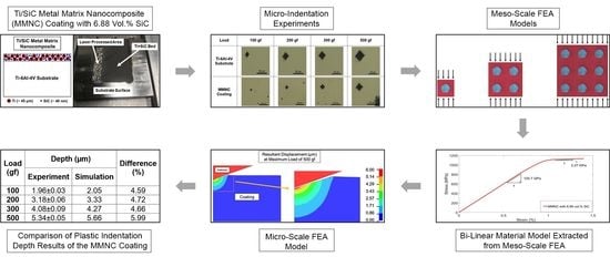
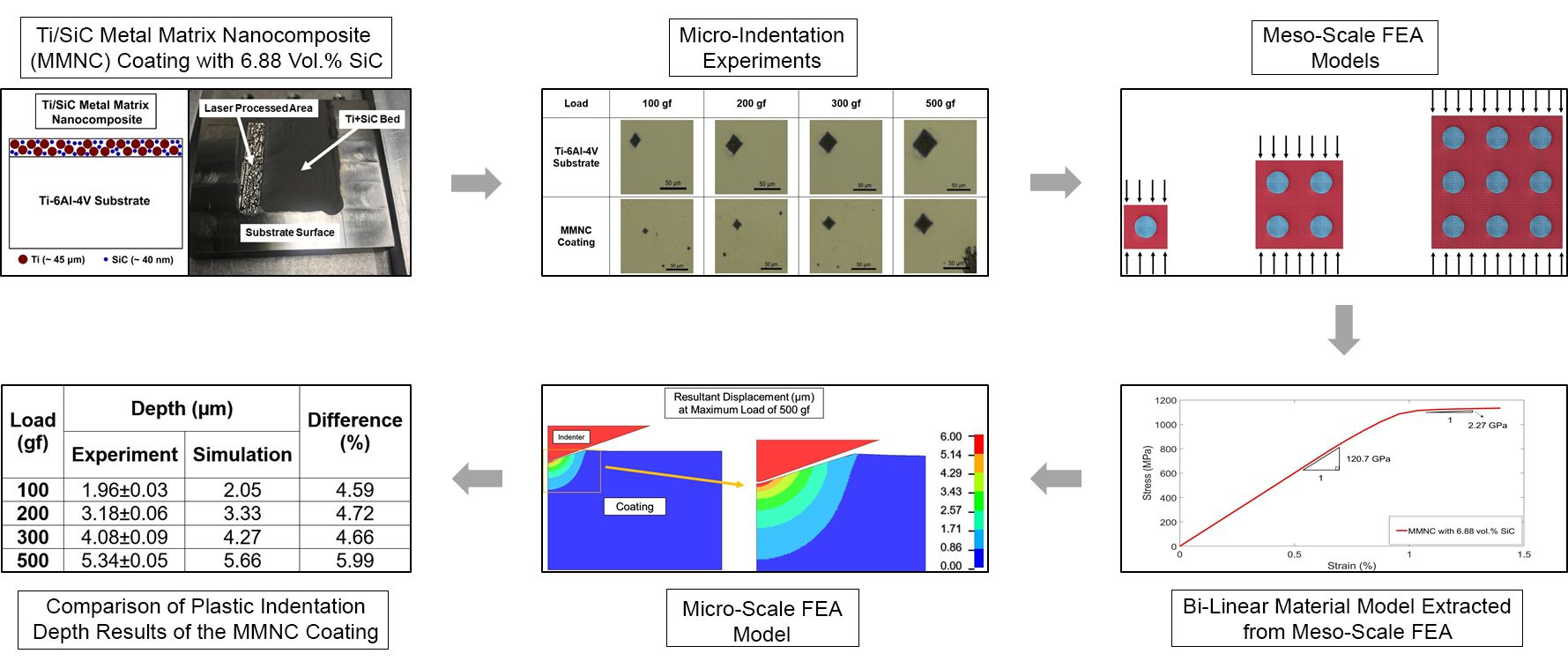
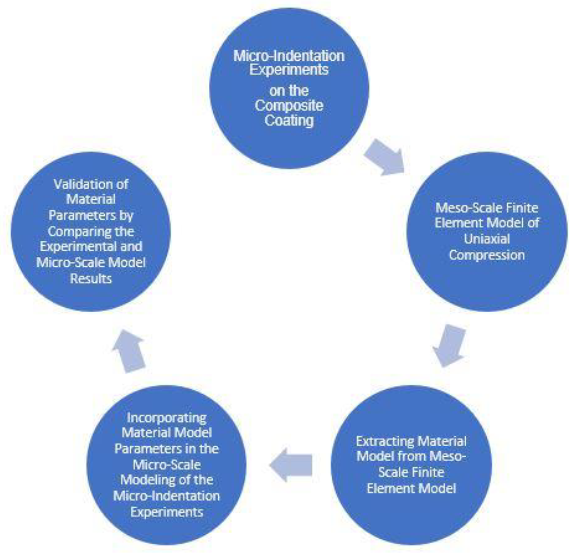
As the literature failed to provide a general approach for identifying the material models of composites, this work proposes a methodology for identifying the material model parameters of composite coatings using a combination of micro-indentation experiments and meso/micro-scale simulations. 
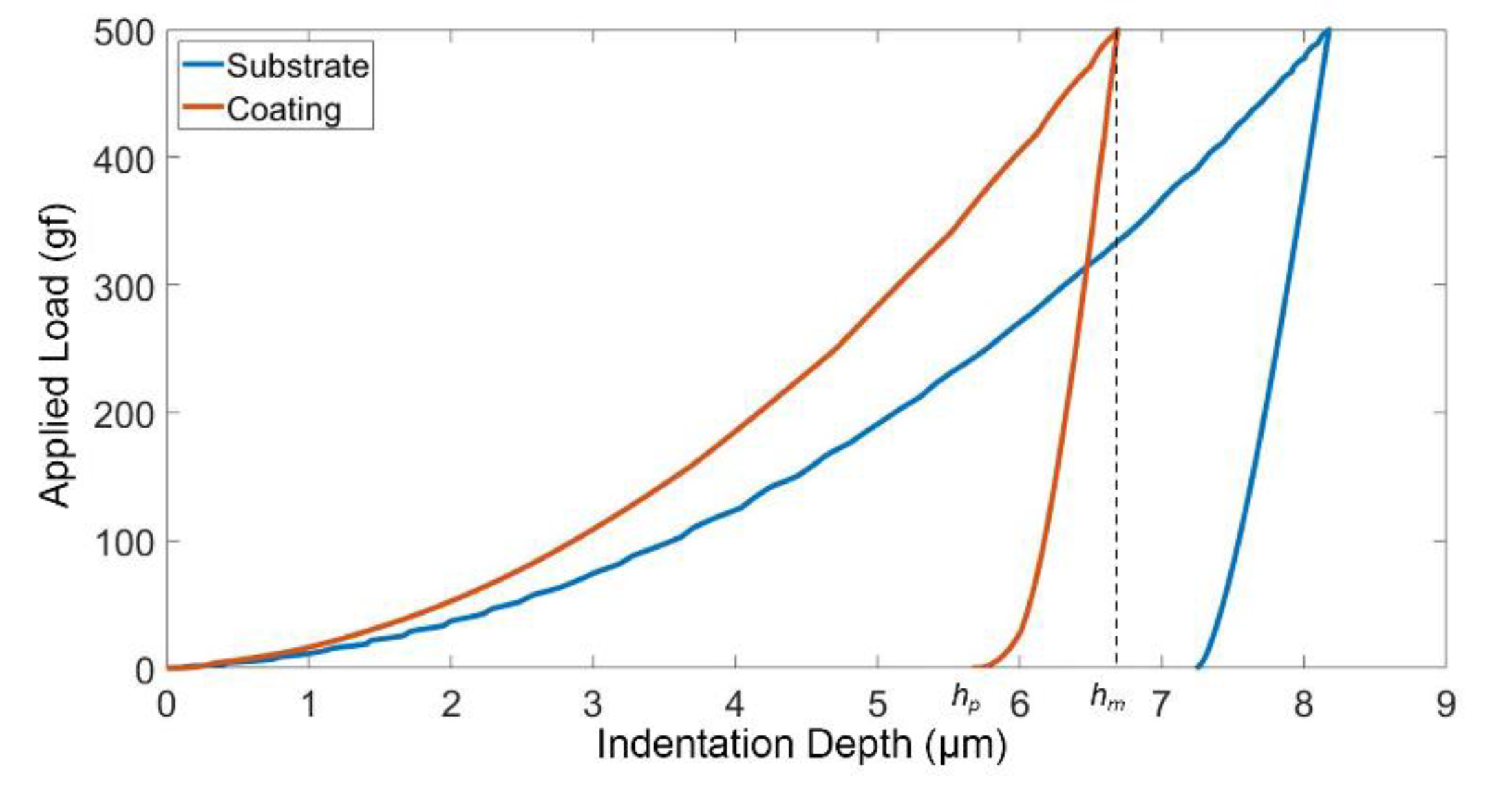
Figure 1 summarizes the approach. The proposed methodology starts with micro-indentation testing on the composite coatings. The testing can be either load controlled or displacement controlled; however, the former was preferred. The residual indentation depth values should be measured.
In the next stage, a unit cell of the composite coating was modeled including the metal matrix and the reinforcement particle sphere suspended in the middle. As this approach assumes that the reinforcement particles are distributed uniformly within the metal matrix, the size of the unit cell was selected such that the volume fraction of the composite coating would be maintained. The appropriate material models were selected for both the reinforcement particles and the metal matrix. A quasi-static uniaxial compression simulation was performed by applying a vertical displacement to the top face of the matrix, and fully constraining the bottom face. The overall stress was then computed by dividing the measured load by the cross-sectional area of the bottom surface. The overall strain was calculated by dividing the displacement at the cube’s top surface by its initial height. The resulting stress–strain curve of the composite coating was extracted from the meso-scale model. Multiple cube sizes were tested, and the results were almost stable.
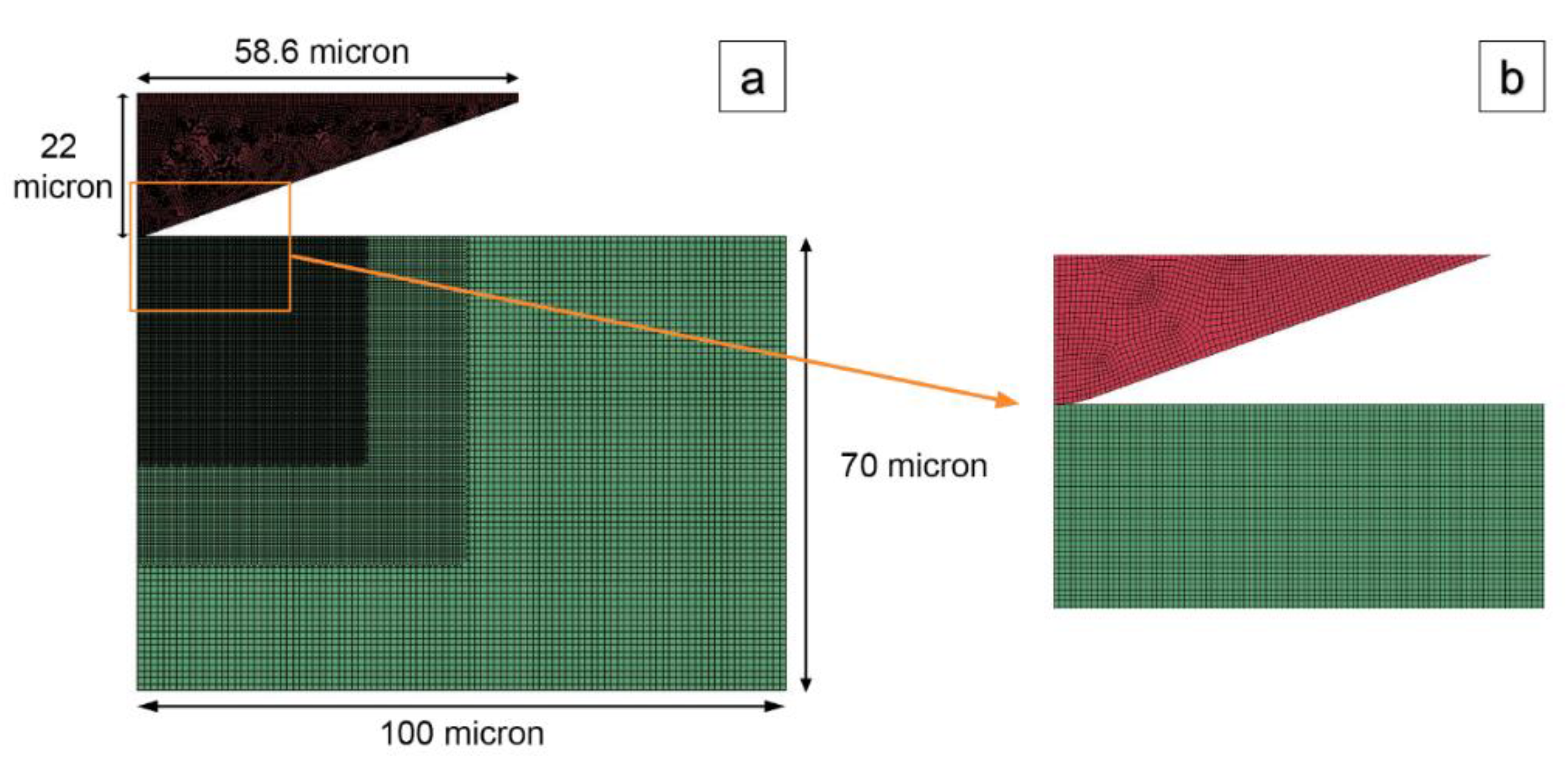
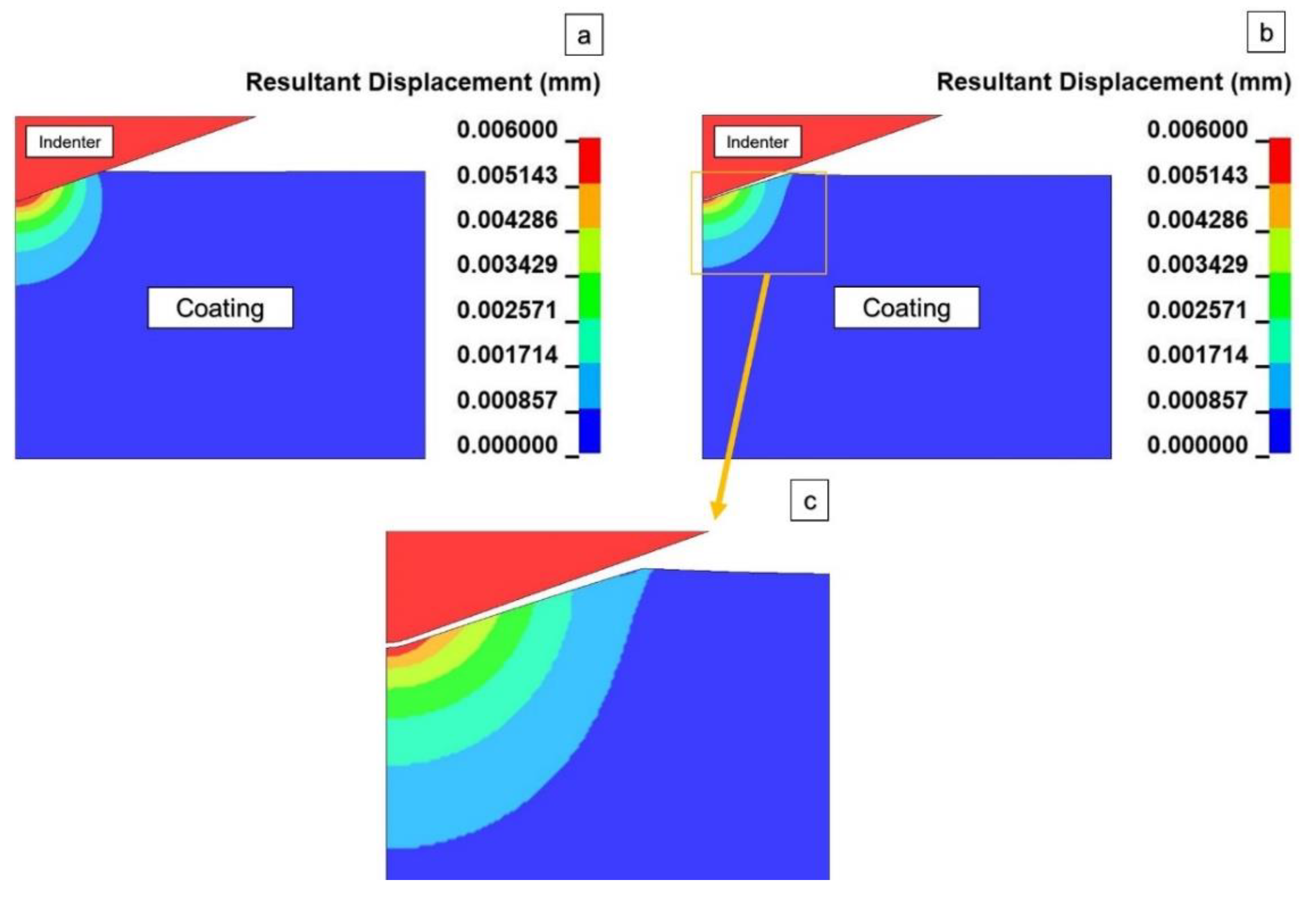
The last stage includes developing an axisymmetric micro-scale finite element model to simulate the micro-indentation experiments of the composite coating. The stress–strain curve parameters obtained from the meso-scale model were incorporated into this micro-scale model. The plastic indentation depth results of the experiments and micro-scale study were compared, to validate the material model parameters of the composite coating.
As an example, the application of this methodology in identifying the material model parameters of a Ti/SiC metal matrix nanocomposite coating fabricated on a titanium substrate using the selective laser melting technique is presented in the rest of this paper.
The following is a brief overview of the paper: Section 2 presents the micro-indentation testing, performed on both the Ti-6Al-4V substrate and Ti/SiC MMNC coating. The meso-scale model of the Ti/SiC MMNC coating, and the micro-scale finite element model of the micro-indentation testing under various loads are presented in Section 3 and Section 4, respectively. Discussions are presented in Section 5, and finally, conclusions are drawn in Section 6.

2. Materials and Methods

2.1. Specimen Preparation

We applied the proposed approach to the Ti/SiC MMNC composite coating deposited by the SLM technique on a titanium substrate. As this particular coating is relatively new, the literature review failed to identify the mechanical characteristics of this material. The closest available material with documented stress-strain curves under various strain rates is MMNC, with 35% SiC and 65% Ti by volume [31]. However, due to the large difference in the SiC volume fraction between this material and the one used in the current research, the results of [31] may not be readily applicable. Amiri’s procedure to obtain the material model parameters require continuous loading and unloading curves, which are not available with the current instrumentation [24]. In addition, this technique requires several indentation tests.
Pure titanium powder was mixed with 5% weight SiC nanoparticles. The average sizes of the titanium powders and SiC nanoparticles were 45 μm and 40 nm, respectively. A ball milling machine (PM100, Retsch Corporation, Haan, Germany) was used to combine the mixture for four hours, operating at a rotation speed of 200 rpm and a ball-to-powder ratio of 5:1, without a protective atmosphere. A layer of the mixed powder, with a thickness of 200 μm, was deposited on the as-milled Ti-6Al-4V substrate (Figure 2). An IPG 500 W fiber laser (YLR-500-AC, IPG Photonics, Oxford, MA, USA) was used to implement the SLM procedure with laser power of 150W, and a height gauge was used to set the coating thickness (200 µm), as shown in Figure 2. The SLM processing parameters, i.e., the laser power and scanning speed, were selected to maintain the processing temperature lower than the melting temperature of nano-SiC. The microstructure characterization indicated that nano-SiC was unaffected or only partially melted after laser processing.
The samples were cross-sectioned, ground with sandpaper of grit up to #1200, and then vibrationally polished with 0.05 μm silica suspension, followed by etching with the Kroll’s reagent (2 mL HF + 4 mL HNO3 + 94 mL H2O) for 15 s. The scanning electron microscopy (SEM, JSM-7100FT, JEOL Ltd., Tokyo, Japan), energy-dispersive X-ray spectroscopy (EDS, JSM-7100FT, JEOL Ltd., Tokyo, Japan), and X-ray diffraction (XRD, D8 Advance, Bruker Corporation, Billerica, MA, USA) techniques were used to characterize the microstructure and to identify the chemical and phase compositions, [16]. The Ti5Si3 and TiC phases, in addition to a small amount of retained β-Ti, were found in the MMNC coating. It was observed that a typical bi-modal structure was formed, as the globular and dendrite grains were surrounded by small equiaxed grains, which were formed due to the combination of the presence of nano-SiC during the solidification process, acting as a nucleation barrier for β-Ti and the decreased cooling rate during the SLM process. As the temperature further dropped, α’martensite was formed within the equiaxed grains. The EDS analysis results showed a more than 90 wt.% presence of Ti within the globular and dendrite grains.

2.2. Micro-Indentation Experiments

A Wilson Tukon 1202 Vickers hardness tester (Wilson Tukon 1202, Buehler, Uzwil, Switzerland) with a diamond indenter was used to conduct the micro-indentation tests on the MMNC-coated samples and titanium substrates. The indentation process was load controlled. A preload was applied for three seconds before ramping up to the desired load for the specified dwell time. The indenter was then pressed down, reaching the maximum load within seven seconds. The full load was maintained for 10 s before reducing it back to zero in seven seconds. The maximum depth of penetration was measured by the hardness tester. The indentation was carried out at different loads: 100, 200, 300, and 500 gram-force (gf). Each indentation test was repeated three times with the same conditions. Typical images of the indentation impressions are shown in Table 1. The maximum penetration depths of the Ti-6Al-4V substrates and MMNC coatings are summarized in Table 2 and Table 3, respectively.
It is seen that by adding 5% weight of nano-SiC, the plastic indentation depth and corresponding hardness (~337 VHN for Ti-6Al-4V substrate and ~700 VHN for MMNC coating [16]) is improved. The following are two reasons: (1) the formation of equiaxed grain, as the columnar grain growth during solidification is restricted by nano-SiC self-assembled at the liquid-crystal interfaces, leading to the physical restriction of diffusion and the formation of equiaxed grains; (2) the dispersion of nano-SiC in the metal matrix, which leads to the dispersion hardening effect and improvement in the strength of the material.

3. Meso-Scale Modeling of the Ti/SiC MMNC Coating

As discussed in Section 1, a meso-scale finite element model of uniaxial compression was developed in LS-DYNA code [
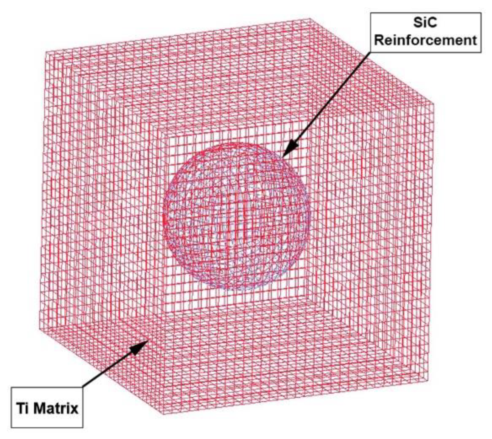
32]. The unit cell of the Ti/SiC MMNC coating was modeled as a Ti matrix with a 40 nm SiC sphere suspended in the middle [16]. This unit cell was a 157 nm cube, which was selected to maintain the SiC volume fraction of 6.88%, or a 5% weight ratio.
A bi-linear plasticity model (MAT_024—piecewise linear plasticity) was used for the Ti matrix [33], while a linear elastic material model (MAT_001—elastic) was used for the SiC. The parameters of these material models are summarized in Table 4, where ρ is density, ν is Poisson’s ratio, E is the modulus of elasticity, σ y is yield strength, and Etan is the tangent modulus. For Poisson’s ratio and modulus of elasticity of the SiC, the values reported in [34] were used in the simulations. The compressive failure strain of SiC was also monitored using the range reported in [35] to assess its structural integrity. Tied surface-to-surface contact was applied between the sphere and the matrix, which means that there was no surface separation under tensile load. A quasi-static uniaxial compression simulation was performed by applying a vertical displacement of 10 nm to the top face of the matrix, while completely fixing the bottom face. The lateral sides of the unit cell were not restrained, similar to [36]. The meso-scale finite element model of the MMNC coating is shown in Figure 3.
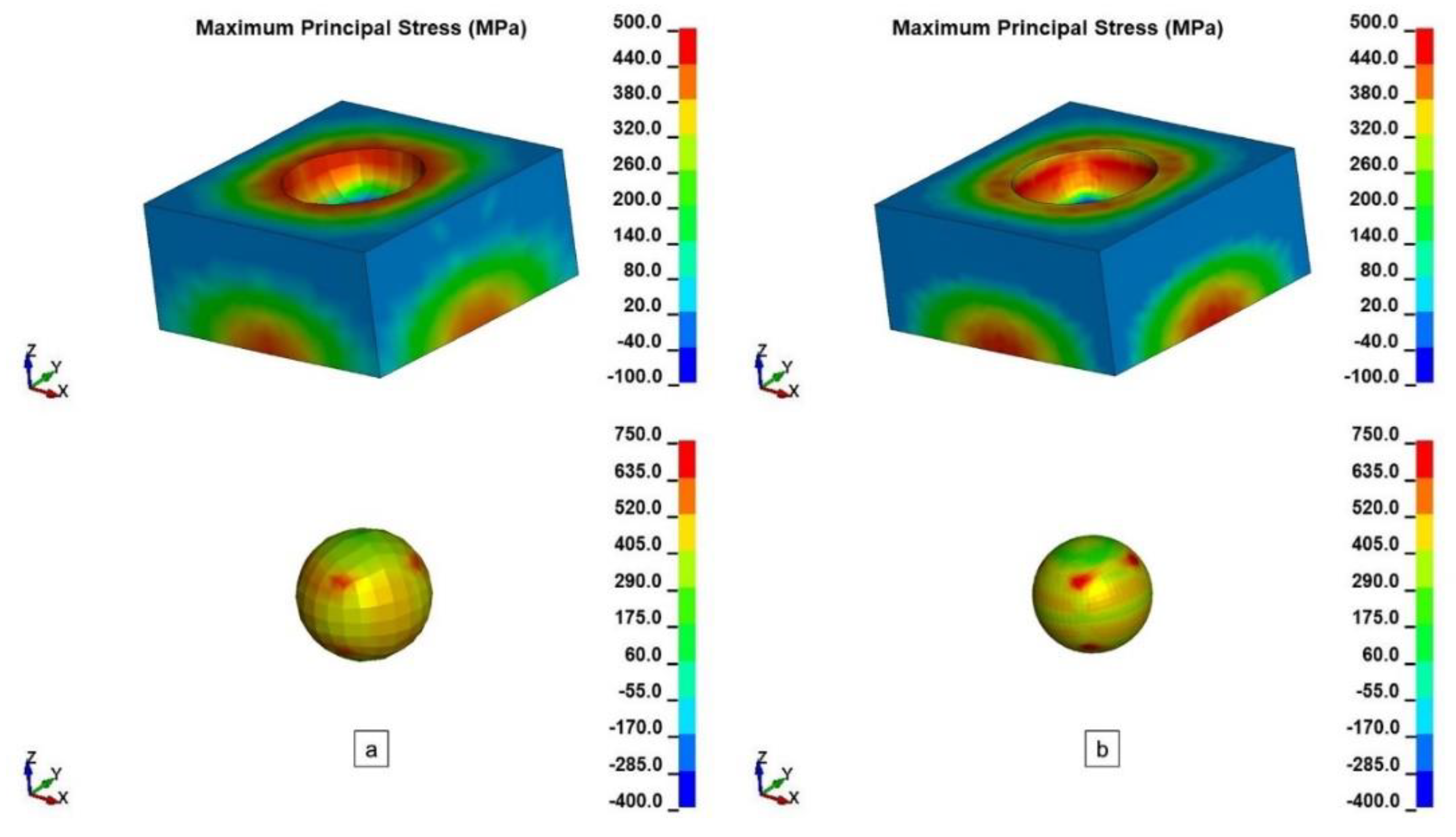
A mesh convergence analysis was performed, considering two cases with average element sizes of 10 and 5 nm, respectively. The actual number of elements in each case is summarized in Table 5. The maximum principal stress contours of the matrix and the reinforcement parts of the models, with 10 and 5 nm element sizes, are shown in Figure 4. In both cases, the maximum strain in the SiC particle was about 0.35%, which is below the failure strain of SiC [35]. The resulting overall stress–strain curves were extremely close for both the 10 and 5 nm element size cases. However, since the model with the 5 nm average element size was able to produce a more defined stress gradient distribution for both materials, this element size was selected for the rest of the meso-scale studies.
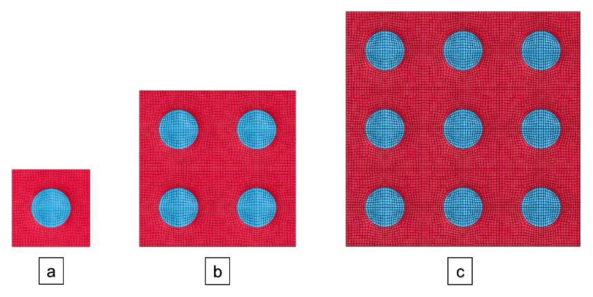
To verify the results, the single cube model was used to build meso-scale models with 8 and 27 SiC spheres. In both models, the spheres were uniformly spaced within the Ti matrix while maintaining the same SiC volume fraction. These three models are shown in Figure 5. The number of elements in these models is also summarized in 
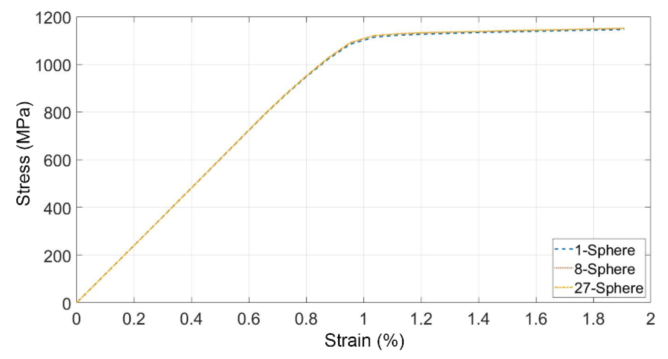
Table 6. The loading and boundary conditions were maintained similarly to the single sphere model. The resulting stress-strain curves were obtained in each case, as explained in Section 1. The overall stress–strain curves of the three models are shown in Figure 6. These curves were almost identical, which showed that expanding the number of cells did not change the resulting stress–strain curve. The resulting modulus of elasticity, yield strength, and tangent moduli were 120.7 GPa, 1122 MPa, and 2.27 GPa, respectively.
To verify the elastic behavior, the resulting modulus of elasticity was compared with the result of the Halpin–Tsai (HT) model, which is a well-accepted formulation for a composite’s modulus of elasticity, Ec [37], expressed as follows:
E c = E m ( 1 + 2 s q V p ) 1 q V p  
where Em is the modulus of elasticity of the matrix; s is the aspect ratio of the reinforcement; Vp is its volume fraction; q is a parameter, which can be written as
q = ( E p E m ) 1 ( E p E m ) + 2 s  
where Ep is the modulus of elasticity of the reinforcement. The parameters used in the Halpin–Tsai model are shown in Table 7. These results show that the Halpin–Tsai modulus of elasticity is almost identical to the result from the meso-scale study, 120.7 GPa.
It may be of interest to compare the resulting bi-linear elastic–plastic parameters with the corresponding parameters of the MMNC, with 35% SiC by volume [31]. As Table 8 shows, the difference in their densities is justified by the lower percentage of SiC in the material under consideration. Similarly, the lower percentage of SiC nanoparticles with high stiffness and rigidity results in lower E and Etan. On the other hand, the yield strength of both materials is very close.

4. Micro-Scale Modeling of the Micro-Indentation Experiments on the Ti/SiC MMNC Coating

4.1. Problem Setup

As discussed in Section 1, a micro-scale finite element model was developed to simulate the micro-indentation experiments of the coated and uncoated specimens. To assess the accuracy of the proposed approach, the finite element model was used to simulate the titanium substrate experiments. The parameters used for titanium substrate were also obtained from ref [38]. This model used a bi-linear material model with the parameters obtained from the meso-scale study for the coating. A 2D axisymmetric finite element model was developed to enable the use of an extremely fine mesh in the contact region. Simulations were performed in the LS-DYNA R 9.0 explicit code [32], using a massively parallel processing (MPP) computer with 768 processors.
Figure 7 shows the mesh used for the indenter and the coating, or substrate. As mentioned in Section 2, the maximum indentation depth was 7 µm, which was significantly smaller than the coating thickness (200 µm). Therefore, a smaller thickness (70 µm) was considered for both the coating and the substrate models, to reduce the computational load of the simulations. Additionally, since the majority of indentation occurred immediately below the indenter, a radius of 100 µm was found to be sufficient to capture the stress and strain fields completely. Following [39], the Vickers indenter was modeled as a cone with an angle of 70.3°, which ensured that the indenter model had the same contact area as the actual square-based pyramid indenter. The height of the indenter was chosen as 22 μm, which was large enough to induce the maximum penetration while not becoming completely embedded within the coating or substrate. This height corresponds to a 58.6 μm radius at the base of the indenter. Following [40], the tip of the finite element indenter model was blunted with a flatness of about 0.8 µm to avoid computational instability due to the mesh tangling below the indenter tip. Since indentation was localized around the tip of the indenter, a refined mesh, with an average element edge length of 0.25 μm, was applied to a 35 μm square that laid immediately below the indenter. This area was surrounded by two larger zones, with average element edge lengths of 0.5 and 1 μm, respectively. Similarly, the indenter was modeled using elements with edge lengths of about 0.25 μm. In total, the model had 42,516 four-node axisymmetric elements. A mesh convergence study was conducted to ensure that the results of this mesh were acceptable. To this end, elements with edge lengths of 0.2 and 0.3 µm were tested for the densest area, the one immediately below the indenter. The three models yielded close results.
The boundary conditions were applied along the centerline of the indenter and specimen and the bottom surface of the specimen by fixing the horizontal and vertical axes, respectively. It has been observed that the diamond indenter has a very low coefficient of friction [41,42]. Therefore, different static and dynamic coefficients of friction between the specimen and the diamond indenter, ranging from 0 to 0.4, were applied to the automatic surface to surface contact. Varying the coefficient of friction did not produce any significant difference in the indentation depths of the specimens, as seen in [43]. Therefore, frictionless contact was used in the simulations.
Similar to the experimental procedures, load-controlled indentation was applied in the simulations. Attempting to model the micro-indentation based on its actual time would be computationally prohibitive. Following the example of other researchers, e.g., Wang et al. [44], who performed a surface micro-indentation simulation of a ceramic coating with the finite element method, using a timescale in the order of nanoseconds, the simulations of micro-indentation testing were performed over an extremely short timescale. In this study, a smooth step load curve was applied to the indenter for a smooth transition in both the loading/unloading regimes. The load duration curves of different phases were as follows: rise of 7 µs, plateau of 10 µs, fall of 7 µs, and zero phase of 3 µs. A linear material model was used for the indenter, with the following properties: density of 3500 (kg/m3), Poisson’s ratio of 0.20, and modulus of elasticity of 1050 GPa [45]. Material models of the coating are also listed in Table 8, respectively.

4.2. Results of the Micro-Scale Simulations

The pressure between the indenter and the coating in the axisymmetric model was a similar order of magnitude to what was observed in the meso-scale study, which justified using the material model obtained from the meso-scale in the micro-scale simulations. It was observed that the stress was uniformly distributed in both the substrate and coating models (Figure 8). Similarly, no stress wave reflection at the boundaries was visible during the simulations. In addition, no oscillations were observed in the load-indentation depth curves (Figure 9). The energy balance was also monitored during the simulations, indicating that the kinetic energy was negligible, compared with the internal energy. These observations showed that the model was reliable in simulating the micro-indentation process.
To help understand the interaction between the indenter and the material, Figure 9 shows the load-indentation depth curves of the substrate and coating for the case of a 500 gf maximum load. In this figure, the maximum and plastic indentation depths are defined as hm and hp, respectively. The results show that the coating has a higher slope in both loading and unloading curves, compared with the substrate, which is an indication of its increased hardness.
The resultant displacement fields of the MMNC coating with a 500 gf maximum load are shown in Figure 10. As expected, most of the deformation due to indentation occurred immediately under the indenter, with the indented material mostly conforming to the shape of the indenter. Once the load removal was completed, some deviation was seen with respect to the indenter. In fact, the rebound was not uniform along the edge of the impression (Figure 10c).

5. Discussion

To validate the material model parameters used in the developed axisymmetric micro-scale models, the average plastic indentation depth (hp) values of multiple elements immediately below the indenter were compared with the experimental results for both the Ti-6Al-4V substrate and MMNC coating, as shown in Table 9 and Table 10, respectively. Both the substrate and coating models resulted in slight plastic depth overestimations. On average, the substrate and coating models overestimated the plastic depths by 2.94% and 4.99%, respectively. The standard deviation in experimental data, possible inconsistent cooling rate in the substrates and coating samples, assumption of uniform distribution of SiC in the matrix, and variation in size of SiC particles may contribute to the slight overestimation of simulation results.

6. Conclusions

Applying a metal matrix nanocomposite coating can enhance the surface quality of a substrate. To optimize surface characteristics, identification of the coating material model is necessary. This work proposed a methodology for identifying the material model parameters of composite coatings using a combination of micro-indentation experiments and meso/micro-scale simulations. Afterward, we identified the mechanical material model of a Ti/SiC MMNC coating on a Ti-6Al-4V substrate using the proposed methodology. The coating was fabricated using the SLM technique, with a 5% weight of SiC nanoparticles and a 95% weight of titanium. The process of indentation was modeled using finite element simulations. This approach indicated that the Ti/SiC MMNC coating behaves as a bi-linear elastic-plastic material model. The results of this single unit model were duplicated when 8 and 27 units were used. It was seen that the cubic cell models of spherically shaped, and uniformly distributed SiC particles performed realistically. These material model parameters were incorporated in an axisymmetric micro-scale study of the experiments. The experimental and simulation results confirmed that the use of SiC nanoparticles enhances surface characteristics. The micro-indentation tests affirmed that the MMNC coating was functional in reducing the indentation depth of the Ti-6Al-4V substrate. On average, the MMNC coating reduced the micro-indentation plastic depth by 28.6%, compared with the Ti-6Al-4V substrate, which indicates that the Ti/SiC MMNC coating is a promising material for many applications, especially those associated with aerospace industries.
It was seen that the proposed approach, using a combination of experimental and simulation techniques, was effective in capturing the post-indentation behavior of the Ti/SiC MMNC coating. This approach can be used for studying the response of coatings with different combinations of reinforcement geometry and volume fraction. The proposed simulations can also be used for parametric studies to customize MMNC coating with specific characteristics such as hypervelocity impact resistance [17,46].

Author Contributions

Conceptualization, M.T., B.O. and A.M.; methodology, P.S. and R.S.; software, P.S. and R.S.; validation, P.S. and R.S.; formal analysis, P.S.; investigation, P.S., R.S. and X.Z.; writing—original draft preparation, P.S. and R.S.; writing—review and editing, M.T., B.O. and A.M.; supervision, M.T., B.O. and A.M.; project administration, M.T., B.O., M.G., Y.L. and A.M.; funding acquisition, P.S., M.T., B.O. and Y.L. All authors have read and agreed to the published version of the manuscript.

Funding

This work was partially supported by an NV NASA EPSCoR Research Infrastructure Development Seed Grant, under award # NNX15AK48A. The Article Processing Charge (APC) for this article was supported by the UNLV University Libraries Open Article Fund.

Institutional Review Board Statement

Not applicable.

Informed Consent Statement

Not applicable.

Data Availability Statement

Not applicable.

Acknowledgments

The authors acknowledge the Texas Advanced Computing Center (TACC) at The University of Texas at Austin for providing HPC resources that contributed to the research results reported in this paper. URL: http://www.tacc.utexas.edu.

Conflicts of Interest

The authors declare no conflict of interest.

References

  1. Moustafa, E.B.; Abushanab, W.S.; Melaibari, A.; Mikhaylovskaya, A.V.; Abdel-Wahab, M.S.; Mosleh, A.O. Nano-surface composite coating reinforced by Ta2C, Al2O3 and MWCNTs nanoparticles for aluminum base via FSP. Coatings 2021, 11, 1496. [Google Scholar] [CrossRef]
  2. Gu, D.; Zhang, H.; Dai, D.; Xia, M.; Hong, C.; Poprawe, R. Laser additive manufacturing of nano-TiC reinforced Ni-based nanocomposites with tailored microstructure and performance. Compos. Part B Eng. 2019, 163, 585–597. [Google Scholar] [CrossRef]
  3. Liu, S.; Pang, M. Effect of TiB2 Content on properties of nickel-coated graphite self-lubricating coating prepared by laser cladding. Coatings 2021, 11, 1501. [Google Scholar] [CrossRef]
  4. Zhang, F.; Liu, T. Nanodiamonds reinforced titanium matrix nanocomposites with network architecture. Compos. Part B Eng. 2019, 165, 143–154. [Google Scholar] [CrossRef]
  5. Mazaheri, Y.; Heidarpour, A.; Jalilvand, M.M.; Roknian, M. Effect of friction stir processing on the microhardness, wear and corrosion behavior of Al6061 and Al6061/SiO2 Nanocomposites. J. Mater. Eng. Perform. 2019, 28, 4826–4837. [Google Scholar] [CrossRef]
  6. Tan, H.; Yang, W. Toughening mechanisms of nano-composite ceramics. Mech. Mater. 1998, 30, 111–123. [Google Scholar] [CrossRef]
  7. Das, S.; Chandrasekaran, M.; Samanta, S. Comparison of Mechanical properties of AA6061 reinforced with (SiC/B4C) micro/nano ceramic particle reinforcements. Mater. Today Proc. 2018, 5, 18110–18119. [Google Scholar] [CrossRef]
  8. Sorci, R.; Tassa, O.; Colaneri, A.; Astri, A.; Mirabile, D.; Iwnicki, S.; Demir, A.G. Design of an innovative oxide dispersion strengthened Al alloy for selective laser melting to produce lighter components for the railway sector. J. Mater. Eng. Perform. 2021, 30, 5184–5194. [Google Scholar] [CrossRef]
  9. Wang, Z.; Song, J.; Wang, T.; Wang, H.; Wang, Q. Laser texturing for superwetting titanium alloy and investigation of its erosion resistance. Coatings 2021, 11, 1547. [Google Scholar] [CrossRef]
  10. Lou, J.; Gao, Z.; Zhang, J.; He, H.; Wang, X. Comparative investigation on corrosion resistance of stainless steels coated with titanium nitride, nitrogen titanium carbide and titanium-diamond-like carbon films. Coatings 2021, 11, 1543. [Google Scholar] [CrossRef]
  11. Eshawish, N.; Malinov, S.; Sha, W.; Walls, P. Microstructure and mechanical properties of Ti-6Al-4V manufactured by selective laser melting after stress relieving, hot isostatic pressing treatment, and post-heat treatment. J. Mater. Eng. Perform. 2021, 30, 5290–5296. [Google Scholar] [CrossRef]
  12. Guo, C.; Zhou, J.; Zhao, J.; Guo, B.; Yu, Y.; Zhou, H.; Chen, J. Microstructure and friction and wear behavior of laser boronizing composite coatings on titanium substrate. Appl. Surf. Sci. 2011, 257, 4398–4405. [Google Scholar] [CrossRef]
  13. Savalani, M.; Ng, C.; Li, Q.; Man, H. In situ formation of titanium carbide using titanium and carbon-nanotube powders by laser cladding. Appl. Surf. Sci. 2012, 258, 3173–3177. [Google Scholar] [CrossRef]
  14. Machethe, K.; Popoola, A.; Adebiyi, D.; Fayomi, O. Influence of SiC-Ti/Al on the microstructural and mechanical properties of deposited Ti-6V-4Al alloy with cold spray technique. Procedia Manuf. 2017, 7, 549–555. [Google Scholar] [CrossRef]
  15. Singh, A.; Bakshi, S.R.; Virzi, D.A.; Keshri, A.K.; Agarwal, A.; Harimkar, S. In-situ synthesis of TiC/SiC/Ti3SiC2 composite coatings by spark plasma sintering. Surf. Coat. Technol. 2011, 205, 3840–3846. [Google Scholar] [CrossRef]
  16. Zhang, X.; Mao, B.; Histed, R.; Trabia, M.; O’Toole, B.; Jennings, R.; Shojaei, P.; Liao, Y. Selective Laser Melting of Ti/SiC Nanocomposite Coating towards Enhanced Surface Performance of Ti64; Materials Science & Technology: Portland, OR, USA, 2019. [Google Scholar] [CrossRef]
  17. Shojaei, P.; Trabia, M.; O’Toole, B.; Jennings, R.; Zhang, X.; Liao, Y. Enhancing hypervelocity impact resistance of titanium substrate using Ti/SiC Metal Matrix Nanocomposite coating. Compos. Part B Eng. 2020, 194, 108068. [Google Scholar] [CrossRef]
  18. Fadida, R.; Shirizly, A.; Rittel, D. Static and dynamic shear-compression response of additively manufactured Ti6Al4V specimens with embedded voids. Mech. Mater. 2020, 147, 103413. [Google Scholar] [CrossRef]
  19. Shishkovsky, I.; Kakovkina, N.; Sherbakov, V. Graded layered titanium composite structures with TiB2 inclusions fabricated by selective laser melting. Compos. Struct. 2017, 169, 90–96. [Google Scholar] [CrossRef]
  20. Zhai, W.; Zhu, Z.; Zhou, W.; Nai, S.M.L.; Wei, J. Selective laser melting of dispersed TiC particles strengthened 316L stainless steel. Compos. Part B Eng. 2020, 199, 108291. [Google Scholar] [CrossRef]
  21. Langi, E.; Zhao, L.G.; Jamshidi, P.; Attallah, M.M.; Silberschmidt, V.V.; Willcock, H.; Vogt, F. Microstructural and Mechanical Characterization of Thin-Walled Tube Manufactured with Selective Laser Melting for Stent Application. J. Mater. Eng. Perform. 2021, 30, 696–710. [Google Scholar] [CrossRef]
  22. Broitman, E. Indentation Hardness Measurements at Macro-, Micro-, and Nanoscale: A Critical Overview. Tribol. Lett. 2017, 65, 23. [Google Scholar] [CrossRef] [Green Version]
  23. Bandyopadhyay, P.; Chicot, D.; Venkateshwarlu, B.; Racherla, V.; Decoopman, X.; Lesage, J. Mechanical properties of conventional and nanostructured plasma sprayed alumina coatings. Mech. Mater. 2012, 53, 61–71. [Google Scholar] [CrossRef]
  24. Amiri, S.; Lecis, N.; Manes, A.; Giglio, M. A study of a micro-indentation technique for estimating the fracture toughness of Al6061-T6. Mech. Res. Commun. 2014, 58, 10–16. [Google Scholar] [CrossRef]
  25. Iankov, R.; Cherneva, S.; Stoychev, D. Investigation of material properties of thin copper films through finite element modelling of microindentation test. Appl. Surf. Sci. 2008, 254, 5460–5469. [Google Scholar] [CrossRef]
  26. Iio, S.; Hasegawa, K.; Fushimi, S.; Yonezu, A.; Chen, X. On compressive deformation behavior of hollow-strut cellular materials. Mater. Des. 2016, 105, 1–8. [Google Scholar] [CrossRef]
  27. Abu Seman, S.A.H.; Ahmad, R.; Akil, H.M. Meso-scale modelling and failure analysis of kenaf fiber reinforced composites under high strain rate compression loading. Compos. Part B Eng. 2019, 163, 403–412. [Google Scholar] [CrossRef]
  28. Ghasemi, M.J.; Silani, M.; Maleki, A.; Jamshidian, M. Micromechanical simulation and experimental investigation of aluminum-based nanocomposites. Def. Technol. 2021, 17, 196–201. [Google Scholar] [CrossRef]
  29. Teng, X.; Huo, D.; Chen, W.; Wong, E.; Zheng, L.; Shyha, I. Finite element modelling on cutting mechanism of nano Mg/SiC metal matrix composites considering cutting edge radius. J. Manuf. Process. 2018, 32, 116–126. [Google Scholar] [CrossRef] [Green Version]
  30. Lepore, M.A.; Sanguigno, L.; Zamani, A.; Berto, F.; Maligno, A.R. Non-linear fatigue propagation of multiple cracks in an aluminium metal matrix composite (AlMMC) with silicon-carbide fibre reinforcement. Mater. Des. Process. Commun. 2020, 2, e119. [Google Scholar] [CrossRef] [Green Version]
  31. Galvez, F.; González, C.; Poza, P.; Llorca, J. The effect of strain rate on the tensile deformation of Ti-6Al-4V/SiC composites. Scr. Mater. 2001, 44, 2667–2671. [Google Scholar] [CrossRef]
  32. Hallquist, J.O. LS-DYNA3D Theoretical Manual; Livermore Software Technology Corporation: Livermore, CA, USA, 1994. [Google Scholar]
  33. Wang, X.; Shi, J. Validation of Johnson-Cook plasticity and damage model using impact experiment. Int. J. Impact Eng. 2013, 60, 67–75. [Google Scholar] [CrossRef]
  34. Hassanzadeh-Aghdam, M.; Haghgoo, M.; Ansari, R. Micromechanical study of elastic-plastic and thermoelastic behaviors of SiC nanoparticle-reinforced aluminum nanocomposites. Mech. Mater. 2018, 121, 1–9. [Google Scholar] [CrossRef]
  35. Petrovic, J.J.; Milewski, J.V.; Rohr, D.L.; Gac, F.D. Tensile mechanical properties of SiC whiskers. J. Mater. Sci. 1985, 20, 1167–1177. [Google Scholar] [CrossRef]
  36. Nobeen, N.S.; Zhong, Y.; Francis, B.A.; Ji, X.; Chia, E.S.; Joshi, S.C.; Chen, Z. Constituent materials micro-damage modeling in predicting progressive failure of braided fiber composites. Compos. Struct. 2016, 145, 194–202. [Google Scholar] [CrossRef]
  37. Alfonso, I.; Figueroa, I.A.; Rodriguez-Iglesias, V.; Patino-Carachure, C.; Medina, A.; Bejar, L.; Pérez, L. Estimation of elastic moduli of particulate-reinforced composites using finite element and modified Halpin–Tsai models. J. Braz. Soc. Mech. Sci. Eng. 2016, 38, 1317–1324. [Google Scholar] [CrossRef]
  38. Osman, R.B.; Swain, M.V. A critical review of dental implant materials with an emphasis on titanium versus zirconia. Materials 2015, 8, 932–958. [Google Scholar] [CrossRef] [PubMed] [Green Version]
  39. Bucaille, J.; Stauss, S.; Felder, E.; Michler, J. Determination of plastic properties of metals by instrumented indentation using different sharp indenters. Acta Mater. 2003, 51, 1663–1678. [Google Scholar] [CrossRef]
  40. Karimzadeh, A.; Ayatollahi, M.; Alizadeh, M. Finite element simulation of nano-indentation experiment on aluminum 1100. Comput. Mater. Sci. 2014, 81, 595–600. [Google Scholar] [CrossRef]
  41. Wu, L.; Holloway, B.C.; Beesabathina, D.; Kalil, C.; Manos, D.M. Analysis of diamond-like carbon and Ti/MoS2 coatings on Ti–6Al–4V substrates for applicability to turbine engine applications. Surf. Coat. Technol. 2000, 130, 207–217. [Google Scholar] [CrossRef]
  42. Bowden, F.P.; Tabor, D. The Friction and Lubrication of Solids; Oxford University Press: New York, NY, USA, 2001; Volume 1. [Google Scholar]
  43. Lu, Y.C.; Kurapati, S.N.V.R.K.; Yang, F. Finite element analysis of cylindrical indentation for determining plastic properties of materials in small volumes. J. Phys. D Appl. Phys. 2008, 41, 115415. [Google Scholar] [CrossRef]
  44. Wang, L.; Zhong, X.; Yang, J.; Tao, S.; Zhang, W.; Wang, Y.; Sun, X. Finite element simulation of surface micro-indentation behavior of yttria stabilized zirconia thermal barrier coatings with microstructural characteristic of columnar grains and sub-grains based on a nonlinear contact model. Comput. Mater. Sci. 2014, 82, 244–256. [Google Scholar] [CrossRef]
  45. Field, J.E.; Freeman, C.J. Strength and fracture properties of diamond. Philos. Mag. A 1981, 43, 595–618. [Google Scholar] [CrossRef]
  46. Shojaei, P.; Scazzosi, R.; Trabia, M.; O’Toole, B.; Giglio, M.; Zhang, X.; Liao, Y.; Manes, A. Material model characterization of a ti/sic metal matrix nanocomposite coating subjected to hypervelocity impact. Procedia Struct. Integr. 2020, 28, 525–537. [Google Scholar] [CrossRef]
Figure 1. Flowchart of the proposed methodology for identifying the material model parameters of composite coatings.
Coatings 12 00092 g001
Figure 2. (a) Preparation of the Ti/SiC MMNC coating on the Ti-6Al-4V substrate; (b) SLM system and (c) laser-processed and unprocessed areas on the Ti-6Al-4V substrate.
Coatings 12 00092 g002
Figure 3. Meso-scale model of the MMNC coating, including the matrix cube and SiC reinforcement sphere.
Coatings 12 00092 g003
Figure 4. Maximum principal stress contours in the middle section of the Ti cube and SiC sphere for (a) 10 nm and (b) 5 nm average element size. The units are in MPa.
Coatings 12 00092 g004
Figure 5. The middle sections of (a) 1-sphere, (b) 8-sphere, and (c) 27-sphere models.
Coatings 12 00092 g005
Figure 6. Stress-strain curve for different meso-scale model arrangements.
Coatings 12 00092 g006
Figure 7. Axisymmetric models of the MMNC coating and indenter: (a) complete model; (b) zoomed view of the contact area.
Coatings 12 00092 g007
Figure 8. Equivalent stress contours of (a) titanium substrate model and (b) MMNC-coated model at 500 gf peak load. The indenter has not been shown for clarity purposes. The units are in MPa.
Coatings 12 00092 g008
Figure 9. Numerical load–depth curves of the Ti-6Al-4V substrate and MMNC-coated models with a 500 gf maximum load.
Coatings 12 00092 g009
Figure 10. Resultant displacement fields of the MMNC coating with a 500 gf maximum load (a) at the peak load, (b) after detachment of the indenter and the coating, and (c) at the zoomed indentation area, after detachment of the indenter and the coating. The units are in mm.
Coatings 12 00092 g010
Table 1. Indentation impressions on the Ti-6Al-4V substrate and Ti/SiC MMNC coating.
Load100 gf200 gf300 gf500 gf
Ti-6Al-4V Substrate Coatings 12 00092 i001 Coatings 12 00092 i002 Coatings 12 00092 i003 Coatings 12 00092 i004
MMNC Coating Coatings 12 00092 i005 Coatings 12 00092 i006 Coatings 12 00092 i007 Coatings 12 00092 i008
Table 2. Experimental plastic indentation depth results on the Ti-6Al-4V substrates.
Load (gf)Depth (µm)
Test 1Test 2Test 3AverageStandard Deviation (%)
1003.012.982.952.981.0
2004.514.394.544.481.8
3005.645.555.675.621.1
5007.166.976.947.021.7
Table 3. Experimental plastic indentation depth results on the Ti/SiC MMNC coating.
Load (gf)Depth (µm)
Test 1Test 2Test 3AverageStandard Deviation (%)
1002.001.941.941.961.5
2003.243.093.213.182.5
3003.964.084.194.082.9
5005.405.295.335.341.1
Table 4. Material model parameters of Ti, SiC, and Ti-6Al-4V.
Material ρ   ( kg m 3 ) νE (GPa) σ y   ( MPa ) Etan (GPa)
Ti44000.30104.04830.46
SiC32100.17450.0--
Ti-6Al-4V44280.31109.810980.69
Table 5. Characteristics of two different meso-scale models for the mesh convergence study.
PartModel with Average Element Size of 10 nm Model with Average Element Size of 5 nm
SiC reinforcement 432 Elements3416 Elements
Ti matrix 3112 Elements25,432 Elements
Table 6. Characteristics of different meso-scale model arrangements.
Part1-Sphere Model8-Sphere Model27-Sphere Model
SiC reinforcement3416 Elements27,328 Elements92,232 Elements
Ti matrix25,432 Elements203,456 Elements686,664 Elements
Total28,848 Elements230,784 Elements778,896 Elements
Table 7. Parameters used in the Halpin–Tsai (HT) model and the modulus of elasticity obtained from the meso-scale study.
sVpq(HT) Model Modulus (GPa)Meso-Scale Model Modulus (GPa)
10.06880.5081121.7120.7
Table 8. Material model parameters of the Ti/SiC MMNC coating with 6.88% and 35% of SiC by volume.
Material ρ   ( k g m 3 ) E (GPa) σ y   ( MPa ) Etan (GPa)
MMNC coating with 6.88% SiC by volume4356120.711222.27
MMNC coating with 35% SiC by volume [31]4002186.01127115
Table 9. Comparison of experimental (Table 2) and the corresponding simulation plastic indentation depth results of the Ti-6Al-4V substrates for different load cases.
Load (gf)Depth (µm)Difference (%)
ExperimentSimulation
1002.98 ± 0.023.042.01
2004.48 ± 0.064.612.90
3005.62 ± 0.055.833.74
5007.02 ± 0.107.243.13
Table 10. Comparison of experimental (Table 3) and the corresponding simulation plastic indentation depth results of the Ti/SiC MMNC coating for different load cases.
Load (gf)Depth (µm)Difference (%)
ExperimentSimulation
1001.96 ± 0.032.054.59
2003.18 ± 0.063.334.72
3004.08 ± 0.094.274.66
5005.34 ± 0.055.665.99
Publisher’s Note: MDPI stays neutral with regard to jurisdictional claims in published maps and institutional affiliations.

