Article

Particle-Size-Dependent Anticorrosion Performance of the Si3N4-Nanoparticle-Incorporated Electroless Ni-P Coating

1
Research Center for Eco Multi-Functional Nano Materials, Sun Moon University, Asan-si 31460, Korea
2
Department of Fusion Science and Technology, Sun Moon University, Asan-si 31460, Korea
3
Department of Environmental and Biochemical Engineering, Sun Moon University, Asan-si 31460, Korea
4
Korea Institute for Rare Metals, Korea Institute of Industrial Technology, Incheon 21999, Korea
*
Authors to whom correspondence should be addressed.
Coatings 2022, 12(1), 9; https://doi.org/10.3390/coatings12010009
Submission received: 20 November 2021 / Revised: 20 December 2021 / Accepted: 20 December 2021 / Published: 23 December 2021
(This article belongs to the Section Corrosion, Wear and Erosion)

Abstract

:
Electroless Nickel–Phosphorus (Ni-P) coating is recognized mostly for its outstanding corrosion and wear-resistant behavior. The intrinsic corrosion and wear-resistant properties of Ni-P-based coating could be further upgraded by incorporating appropriate second-phase additive particles into the coating matrix. However, such properties of the Ni-P-based coating greatly rely on the surface and microstructural evolution arising with the co-deposition of the additive particles. In this study, submicron Si3N4 (average size ~200 nm) and nano Si3N4 (average size ~20 nm) particles were incorporated while depositing a Ni-P alloy in a low-carbon steel substrate to develop the Ni-P-Si3N4 composites through the electroless coating method. The 20 nm Si3N4-incorporated composite coating constituted fewer defects such as cavities and micropores on the surface, but such defects significantly appeared on the surface of the composite after the incorporation of 200 nm Si3N4 nanoparticles. Subsequently, the composite Ni-P-Si3N4, developed with the co-deposition of 20 nm nanoparticles, is enriched with enhanced anticorrosion characteristics compared with the composite developed with 200 nm nanoparticles. The enhancement of anticorrosion behavior was attributed mainly to the Si3N4 nanoparticles that covered the substantial volume of the coating and led to inhibit the formation of corrosion active sites such as defects and metallic Ni phase.

Graphical Abstract

1. Introduction

Metals play a significant role in the development of modern human civilization. Machines, equipment, infrastructures, technologies, commodities, etc., all rely on it. Unfortunately, most of the naturally abundant and, of course, cost-effective metals are hardly suitable for the prevailing engineering applications in many areas. Over time, they lose their strength or collapse due to the adverse working environment. Metallic corrosion remains one of the major issues that leads to devastating equipment failure. It occurs in industrial plants such as electrical, chemical processing, food processing, construction, etc., imposing not only a compelling economic burden but also jeopardizing public health, safety, and the environment.
Electroless Ni-P-based coating is vastly accepted as corrosion-resistant coating together with excellent tribological and wear properties [1,2,3,4]. Moreover, it possesses a superior uniformity despite the complexity of the structure of the engineering components to be coated [5]. The corrosion-resistant behavior of Ni-P-based coatings not only depends on surface conditions such as defects and micropores [6,7] but also on the phosphorus (P) content [8,9]. The Ni-P coating with higher P-content is enriched with enhanced anticorrosion ability than that of low-P-content coatings [10,11,12]. However, low-P coatings possess high hardness, microcrystalline microstructure, etc.; therefore, these coatings are desired to enhance the mechanical properties of the machine parts [13,14]. In addition, it is worth mentioning that the co-deposition of the second-phase particles into the coating matrix are found to boost further the inherent properties such as hardness, anticorrosion, antiwear, etc., not only in Ni-P-based coatings but also in plasma electrolytic oxidation (PEO) coatings [15]. Therefore, particle-incorporated Ni-P-based composite coatings can be employed to achieve the desired performance of the engineering parts [16,17,18].
Silicon nitride (Si3N4) is well known for its exceptional thermomechanical properties such as high hardness, thermal shock resistance, high strength, and fracture toughness. These properties, in connection with low density, chemical inertness, and oxidation resistance have made it one of the relevant structural materials for manufacturing applications. Owing to such outstanding properties, highly stable nanoparticles of Si3N4 are being chosen as additive particles to intensify the inherent corrosion and wear-resistant properties of Ni-P-based coatings. Previous work [19] has revealed that the incorporation of Si3N4 nanoparticles could improve the antiwear behavior of electroless Ni-P coatings, where the distributed nanoparticles have largely inhibited the initiation and propagation of the microcracks.
There are some reports on the effect of Si3N4 particles on the mechanical and corrosion behavior of the electroless Ni-P coating. Ramesh et al. [20,21] found an improvement in mechanical properties of electroless Ni-P coating after the incorporation of micron-sized (2 to 20 µm) Si3N4 particles. Wang et al. [22] reported the enhancement of microhardness and wear properties of the Ni-P-Si3N4 composite prepared by incorporation of Si3N4 nanowires. Das et al. [8] reported the improvement in anticorrosion characteristics of the Ni-P-Si3N4 composite when co-deposited with 1.6 µm Si3N4 particles. Balaraju et al. [23,24] reported a similar result in the improvement of anticorrosion behavior of the Ni-P-Si3N4 composite, where the authors incorporated micron-sized Si3N4 particles. Meanwhile, Sarret et al. [25] reported an increment in microhardness after the co-deposition of 50 nm Si3N4 nanoparticles in the Ni-P matrix via the electroless method. Despite several studies on Si3N4 particle co-deposition in the Ni-P-based coatings, a systematic investigation of the particle size effect on the anticorrosion performance of the Ni-P-Si3N4 composite is still a subject of investigation. As the anticorrosion property of the coatings is highly influenced by the surface and microstructural characteristics, the defect-free coatings are advantageous to impede the corrosion phenomena.
In this study, submicron (~200 nm) and nanosized (~20 nm) Si3N4 particles are taken as additive particles to prepare the Ni-P-Si3N4 composites coated on a low-carbon steel substrate. We have investigated the overall effect of the particle size of Si3N4 nanoparticles on surface morphology, microstructures, and electrochemical corrosion behavior of the Ni-P-based coatings prepared via electroless technique for which the P-content is in the range of 9–11 wt.%.

2. Materials and Methods

2.1. Coatings on Low-Carbon Steel

The coatings were performed on low-carbon steel (Jungdo test instrument Lab, Seoul, Korea) panels of size 2 cm × 1.5 cm × 0.2 cm. Before coating, the panels were polished with the aid of 600, 800 and 1200 grit SiC abrasive papers followed by acetone cleaning. The polished panels were further treated separately with 10% NaOH (w/w) and 10% H2SO4 (v/v) solution for 10 and 2 min, respectively at room temperature (25 °C). Deionized (DI) water was used to rinse the panels properly after each treatment process and the panels were finally transferred to the bath for the coating.
The bath composition can be found elsewhere [26]. The surfactant/antipitting agent, Sodium Dodecyl Sulfate (SDS), was kept at 0.05 gL−1 in the bath. The pH of the bath was adjusted to 5.0 at 25 °C by NaOH and the plating temperature was maintained at 80 ± 2 °C during an hour of coating process. The commercially available Si3N4 powder of average particle size 20 nm (Get Nano Materials, Las Cruces, NM, USA) and 200 nm (Toyo soda manufacturing. Co., Ltd., Tokyo, Japan) was used as the additive particles (Figure S1. Supplementary Information). A slurry was prepared from the additive Si3N4 powder and SDS in a 50 mL bath solution and sonicated for an hour to disperse agglomerated Si3N4 particles. For the improvement of adhesion of the composite coating, the substrates were first coated in a plain Ni-P coating bath for 10 min before the insertion of the slurry. The initial concentration of the Si3N4 powder in the bath was kept at 0.4 gL−1. The bath was magnetically stirred continuously at 250 rpm throughout a one-hour coating duration.
We use the symbol ‘SN’ and ‘nSN’ to represent the Si3N4 particles of average size 200 and 20 nm, respectively, and the following nomenclature is assigned to the coating specimens to distinguish them from each other.
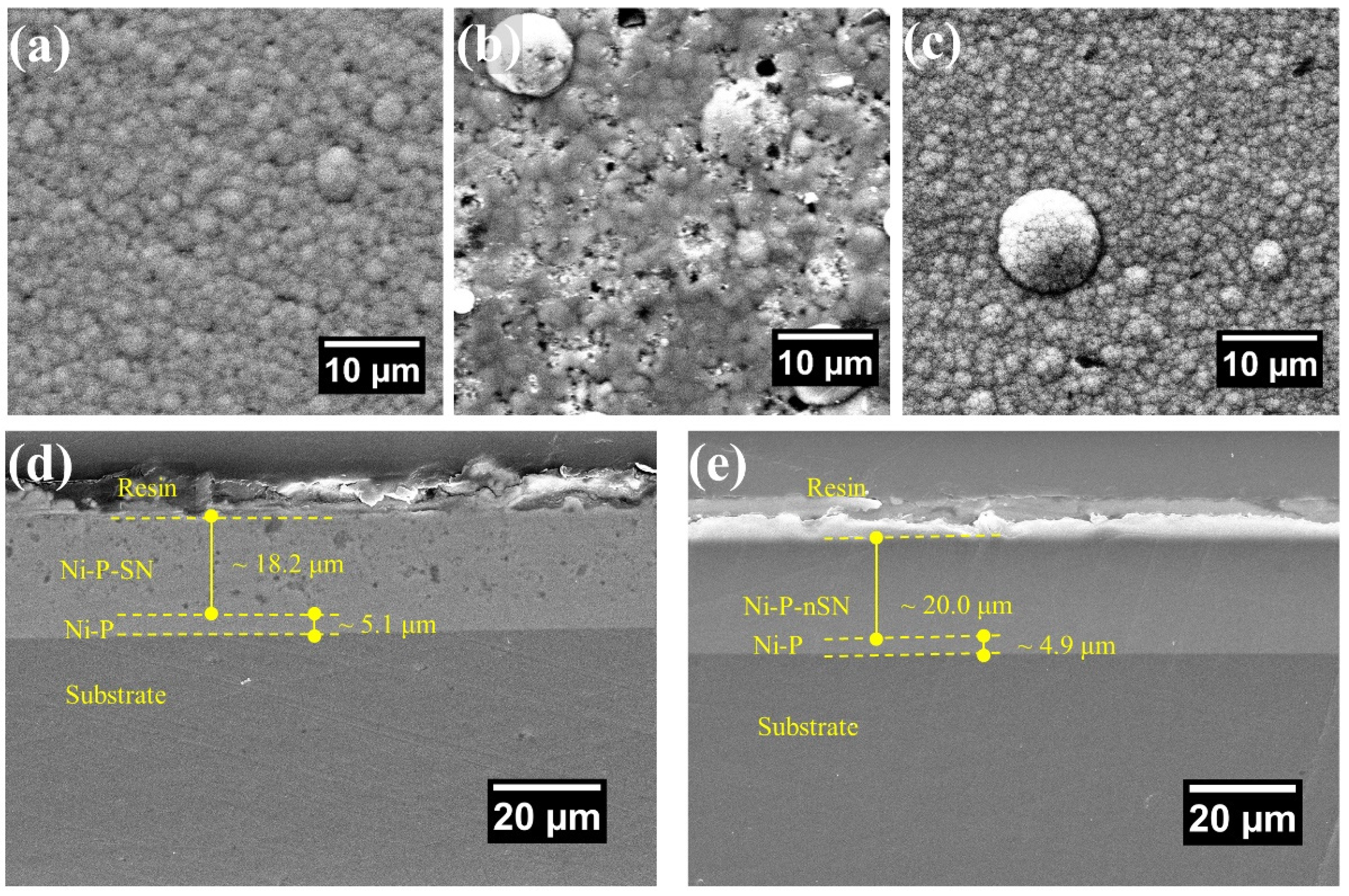
  • Ni-P → Nickel-Phosphorus coating.
  • Ni-P-SN Si3N4 submicron particles (200 nm) incorporated Ni-P-Si3N4 coating.
  • Ni-P-nSN Si3N4 nanoparticles (20 nm) incorporated Ni-P-Si3N4 coating.

2.2. Characterization

Field emission scanning electron microscope (FE-SEM, JSM-6700F, JEOL, Tokyo, Japan) furnished with an energy dispersive X-ray spectroscope (EDAX, AMETEK Co., Ltd., Mahwah, NJ, USA) was used to inspect the surface morphology, cross-section, and elemental composition of the coatings with an operating voltage of 20 kV. The SEM images of the coating surface morphologies were taken in their as-coated state without further treatment (such as polishing, etching, etc.). However, while taking the images of the coating cross-section, the specimens were polished by 1200 grit sandpaper. A transmission electron microscope with 300 kV of operating potential (TEM, Titan TM 80–300, FEI, Hillsboro, OR, USA) was employed to perform the microstructural and elemental analysis. The TEM samples were prepared by employing a focused ion beam technique (FIB, Helios G4, Thermo Scientific, Waltham, MA, USA). X-ray diffraction (XRD, RINT2200, Rigaku, Tokyo, Japan) was employed to study the coating phases with an operating voltage of 40 kV, current 40 mA, and Cu K-α X-ray source (1.54 Å) according to reference [27] at the scanning rate of one degree per minute.

2.3. Anti-Corrosion Performance Evaluation

Potentiodynamic polarization (Tafel) curves and electrochemical impedance spectroscopy (EIS) techniques were employed to evaluate the anticorrosion behavior of the coatings in non-de-aerated NaCl (3.5 wt.%) solution at a temperature of 25 °C. A workstation (Iviumstat, Ivium Technologies, De Lismortel, The Netherlands) comprised of three-electrode system was used to carry out the electrochemical measurements. A saturated calomel electrode (SCE) and a platinum gauze were used as the reference electrode (RE) and counter electrode (CE), respectively, and the coating specimen itself was a working electrode (WE). A stable open circuit potential (OCP) was achieved when the holding time of the coating specimens was 60 min in the corrosive NaCl solution and then the polarization (Tafel) curves were recorded at a potential range of −600 mV to +600 mV (vs SCE) with respect to the OCP. The EIS tests were conducted in the frequency range of 100 kHz − 0.01 Hz at OCP for which the applied AC perturbation was 1 mV. All the electrochemical measurements were conducted in a Teflon kit. The kit was designed in a way that allowed to expose specimen area of 1 cm2 in the corrosive medium during the measurements. Three sets of coating specimens were evaluated by this method and the average data of each were plotted. The Nyquist curves obtained after the EIS tests were fitted using Z-view software based on an equivalent circuit-fitting model. The elemental mass quantification of the corrosion products was conducted via inductively coupled plasma mass spectrometry (ICP-MS, iCAP Q, Thermo Fisher Scientific, Waltham, MA, USA).

3. Results and Discussion

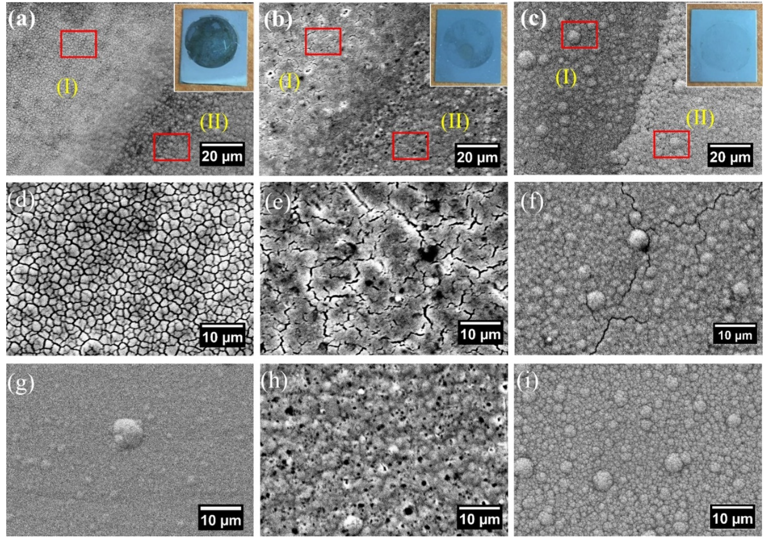
3.1. Coating Surface and Cross-Section

The SEM images of the surface and cross-section of the coatings are shown in Figure 1. Ni-P coating possesses a characteristic smooth surface morphology (Figure 1a), while the Ni-P-SN appears to have a rougher surface containing cavities and voids (Figure 1b). However, the surface appears smooth in the case of Ni-P-nSN coating (Figure 1c) and bears no significant differences from the reference Ni-P coating (Figure 1a). The incorporated nSN particle has not altered the intrinsic coating mechanism of Ni and P atoms in Ni-P-nSN specimen; therefore, the coating surface consists of significantly fewer surface defects such as cavities, voids, and irregular growth of the nodules.
The images of Ni-P-SN and Ni-P-nSN coating cross-sections shown in Figure 1d,e, respectively, also support the coating natures as observed in the surface morphological characteristics. The cavities can be seen in the cross-sectional image of Ni-P-nSN coating (Figure 1d) similar to that in the surface (Figure 1b), whereas the Ni-P-nSN cross-section is free from such cavities (Figure 1e). Furthermore, the coating thickness also differs in both composites. The Ni-P-SN composite coating has a thickness of ~18.2 µm, whereas it is ~20.0 µm in Ni-P-nSN. However, the coating thickness of Ni-P-nSN is almost the same as that of the Ni-P coating (~20.1 µm) [19]. As mentioned in the experimental section, a coating of Ni-P layer on the substrates has been carried out for 10 min before mixing the slurry of Si3N4 particles with the bath in the same coating conditions. Therefore, both Ni-P-SN and Ni-P-nSN specimens consist of a layer of Ni-P with a similar thickness of around 5 µm in between the substrate and the composite coating layers. The layer Ni-P can be easily seen in the SN-particle-incorporated coating (Figure 1d). However, the contrast of the Ni-P layer cannot be distinguished in nSN-particle-incorporated coating since the size of nSN particles is beyond the resolving limit of SEM. Thus, the contrast of Ni-P and Ni-P-nSN layers appear indistinguishable (Figure 1e). The results of the coating thickness measurement also suggest that the coating process is interfered by the size of the incorporated particles. Larger particles, SN, have produced more cavities in Ni-P-SN surface. A kink could be generated at the larger particle sites compared with particle-free sites, thus, creating unequal surface asperities causing the formation of cavities, voids, and micropores during the coating process. However, cavities almost disappeared in Ni-P-nSN composite due to the filling of such spaces by nSN particles. Due to its fine size (~20 nm), the nSN particles are assimilated appropriately in the Ni-P matrix. Furthermore, the surface asperities of adhered particle and matrix regions have remained almost at an equal level because the formation of cavities and voids has been suppressed during the deposition of Ni and P atoms. Thus, the Ni-P-nSN composite coating comprised fewer defects in comparison with the Ni-P-SN composite coating.

3.2. Phase and Microstructural Study
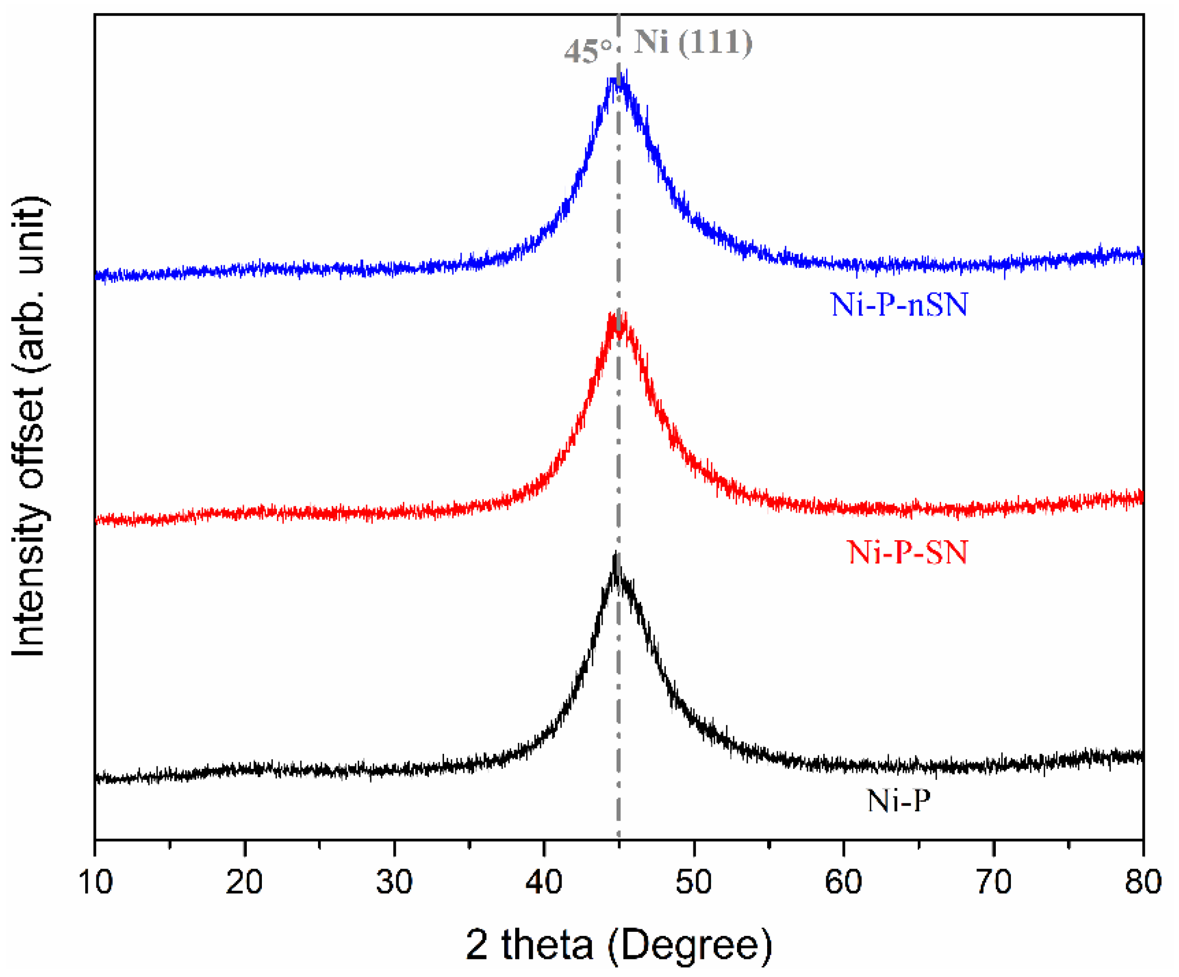
3.2.1. XRD Analysis

The XRD spectra (Figure 2) consist of a broad diffraction pattern ranging from 36° to 56° in all the specimens in which the peak centered at 45° belongs to Ni (111) plane. The XRD patterns point out that the coating specimens are composed of ultra-nano Ni crystallites and amorphous Ni-P alloy matrix [28,29,30]. The shape of the diffraction peaks of Ni-P-SN and Ni-P-nSN composite coatings resembles the diffraction peaks observed from plain Ni-P coatings where no other additional peaks are detected. The quantity of incorporated SN and nSN particles in the coating may not be sufficient to be uncovered by the X-ray so that corresponding peaks could not be observed.

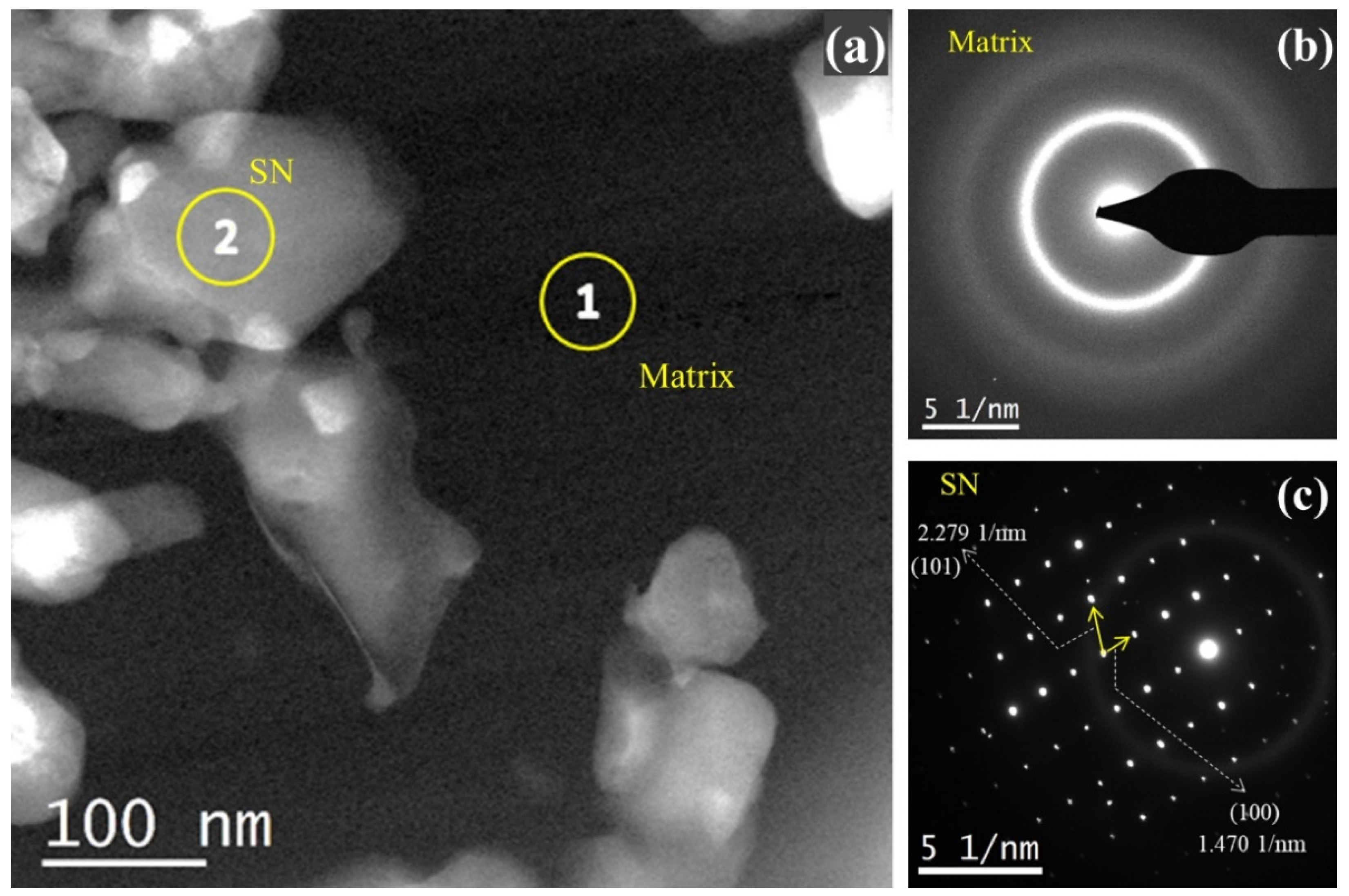
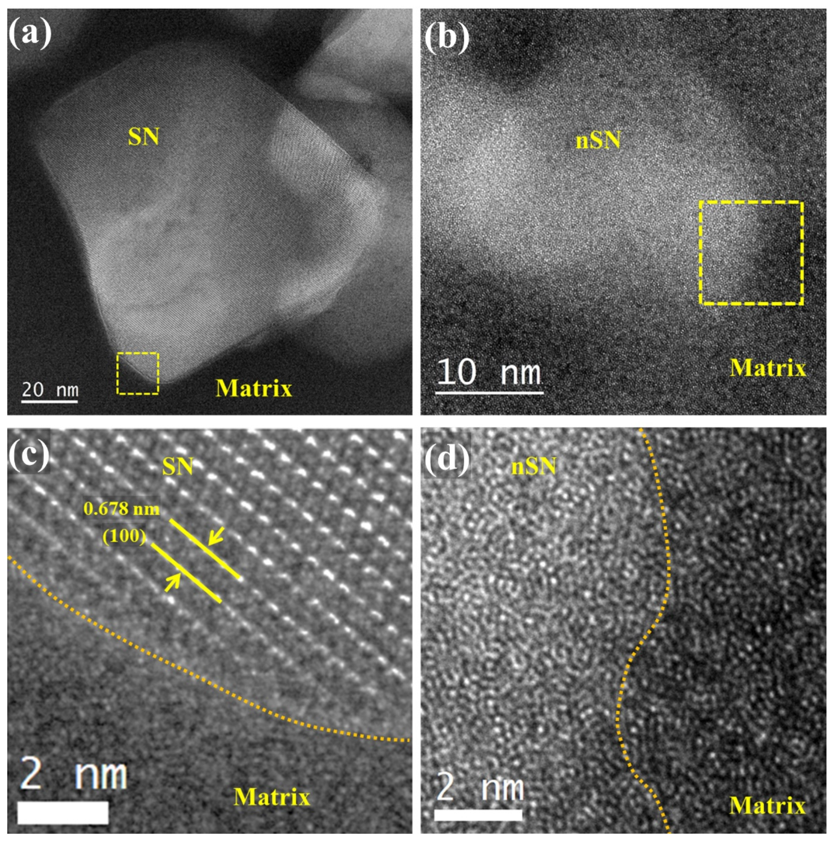
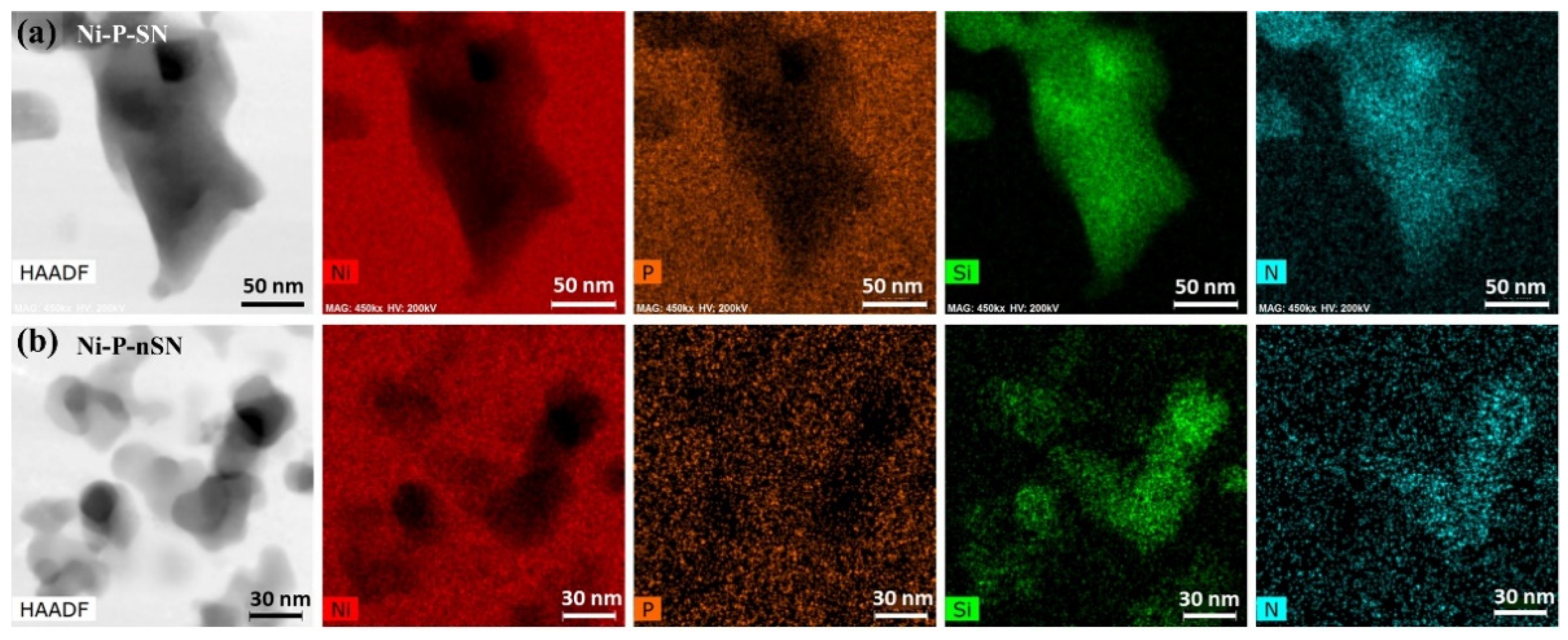
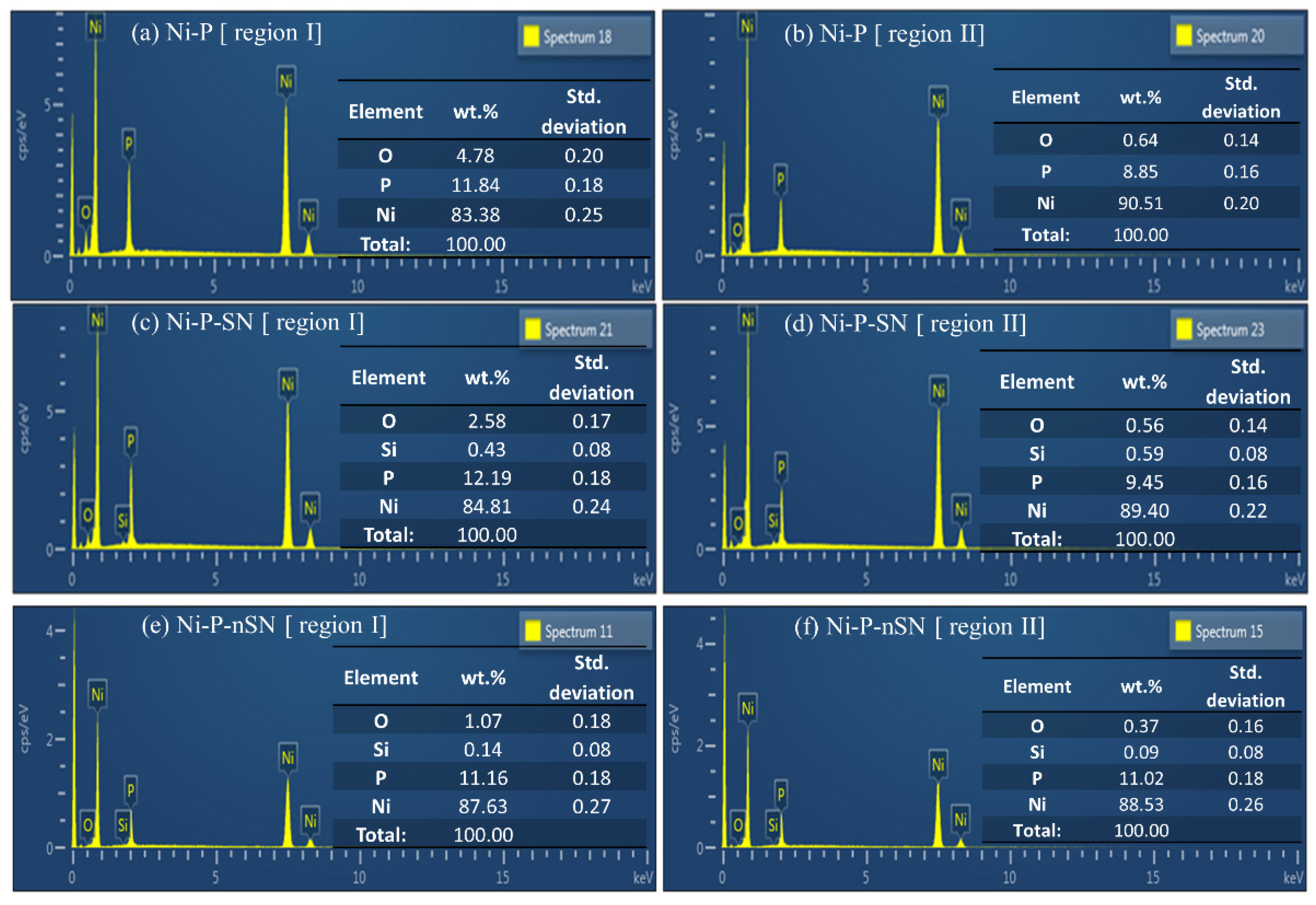
3.2.2. TEM, HRTEM, and EDS Analysis

The microstructures of the Si3N4-particle-incorporated composite coatings were studied further via TEM in order to confirm the phases and particle incorporation in the Ni-P matrix. Figure 3 depicts the TEM micrograph and the selected area electron diffraction (SAED) patterns of Ni-P-nSN composite. The TEM micrograph shown in Figure 3a consists of the Ni-P matrix, dark contrast indicated by 1, and the co-deposited SN particles, bright contrast indicated by 2. The SAED pattern observed from the Ni-P matrix, shown in Figure 3b, consists of diffused circular rings. It indicates that the matrix is composed of amorphous phases of Ni-P alloy and ultrafine Ni crystalline phases as suggested by the XRD result. However, the SAED pattern collected from the SN particle is composed of bright dots implying its crystalline nature. The planes (100) and (101) of SN particle are identified in the SAED pattern (Figure 3c) with the corresponding value 0.680 and 0.439 nm of spacing, respectively.
Similarly, the TEM and SAED micrographs of Ni-P-nSN composite coating are shown in Figure 4, which depict co-deposited nSN particles (Figure 4a). In addition, the SAED patterns (Figure 4b,c) collected from the matrix and nSN particle both comprise the diffused circular ring patterns, thus, indicating the amorphous nature of the matrix and incorporated particle. The HRTEM images of particle-matrix regions of Ni-P-SN and Ni-P-nSN (Figure 5a,b) also describe the crystallinity behavior of the incorporated particles as well as the coating matrix. Distinct (100) plane with lattice spacing 0.678 nm of SN particle (Figure 5c), also observed in the SAED pattern (Figure 3c), closely matches to α-Si3N4 phase (JCPDS No. 76-1408). However, no such well-defined planes are observed in the HRTEM image of nSN particle (Figure 5d); thus, it is in the amorphous phase.
In addition, the interface separating the particle and matrix can easily be distinguished in Ni-P-SN specimen but diffused in the Ni-P-nSN due to the amorphous nature of the incorporated nSN particle and the matrix. The presence of Si3N4 in the matrix is further confirmed via EDS elemental mapping of the particle-matrix regions of the composite coatings (Figure 6). The images showing the elemental mapping of Ni, P, Si, and N suggest that the Si3N4 particles are well-embedded in the Ni-P alloy matrix (Figure 6a,b).

3.3. Corrosion Behavior Evaluation

The anticorrosion behavior of the coatings has been evaluated by the electrochemical method. This method has been proven as an extraordinary tool to assess the coating’s corrosion-resistant capability. The electrochemical behavior and corrosion rates can be predicted by the polarization curve over a wide range of potentials [31]. The parameters such as corrosion potential ( E c o r r ) , corrosion current density ( j c o r r ) , solution resistance ( R s ) , polarization resistance ( R p ) , charge transfer resistance ( R c t ) , constant phase element ( C P E ) , and corrosion rate ( C R ) of the coatings are determined from the Tafel extrapolation and EIS curve-fitting methods. Depending on these parameters and other supporting outcomes, the judgment on corrosion-resistant performance of the coatings has been made.

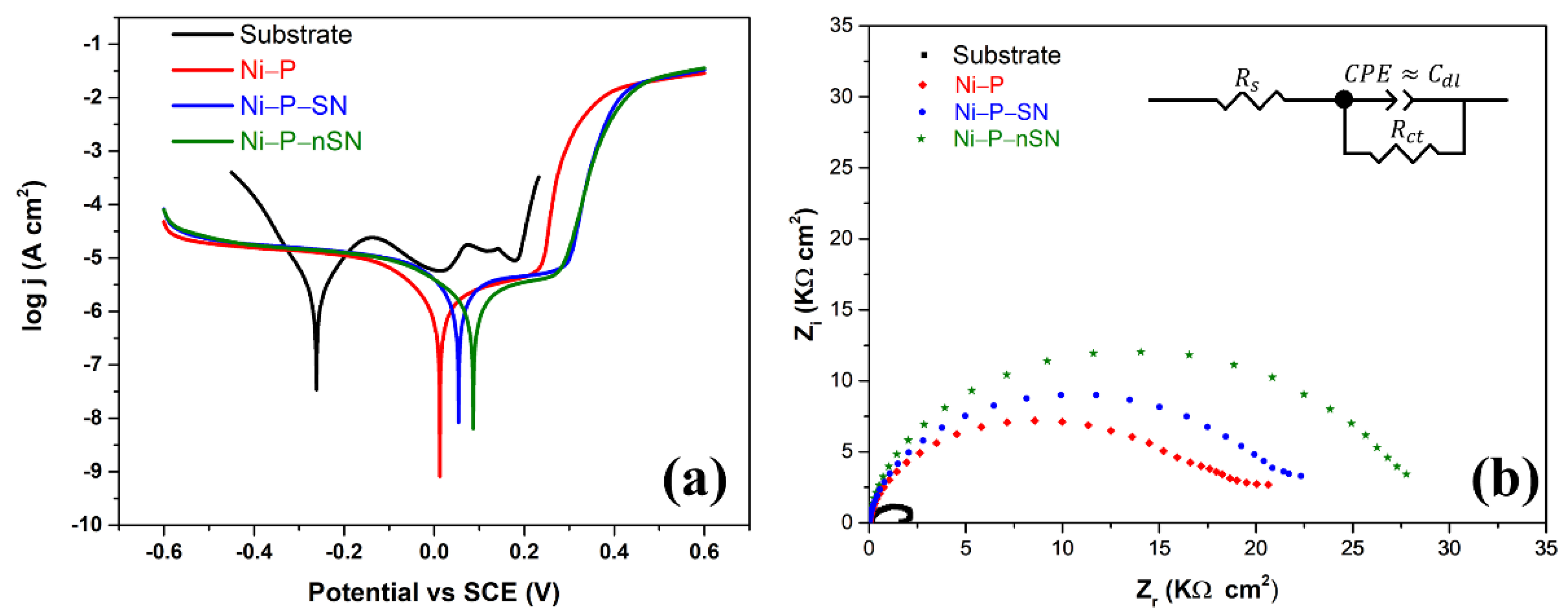
3.3.1. Tafel and Nyquist Curves

Tafel and Nyquist plots of the specimens, recorded in 3.5 wt.% non-de-aerated NaCl solution, are shown in Figure 7a,b, respectively. The equivalent circuit diagram is presented in the inset of Figure 7b. The half-cell reactions associated with anodic and cathodic processes in the Ni-P system involve Ni dissolution accompanied by electron release and the formation of H2 gas as elucidated by Pletcher and Walsh [32]. The half-cell reactions associated with the anodic phenomena can be expressed by the following reactions:
Ni   Ni 2 + + 2 e   ( Anodic   process   for   the   coating )
Fe   Fe 2 + + 2 e   ( Anodic   process   for   the   substrate )
The cathodic phenomena involve H2 formation and the reduction of dissolved oxygen in the non-de-aerated NaCl solution by the following reactions:
2 H + + 2 e   H 2
O 2 + 4 e + 2 H 2 O   4 OH   and
O 2 + 4 H + + 4 e   2 H 2 O
The hydroxide ions ( OH ) react with Ni 2 + ions to form Ni ( OH ) 2 as the corrosion product [33]. The polarization (Tafel) curves shown in Figure 7a are governed by the above equations. If the coating is composed of corrosion propagation channels, such as micropores or cracks; then, the corroding species can reach the substrate and, as a result, the substrate begins to corrode.
The C R is directly proportional to j c o r r as given by
C R = ( 3.27 × 10 3 )   j c o r r   E w ρ
where E w and ρ represent the equivalent weight (g) and density (g cm−3) of the corroding metal, respectively. The unit of j c o r r is μA cm−2.
The parameters obtained from the Tafel extrapolation and Nyquist curve fitting methods are presented in Table 1. The E c o r r of the low-carbon steel substrate is in the negative potential region (−0.260 V). All the coated specimens have higher E c o r r value in the positive region compared with that of the substrate. Furthermore, a comparably lower j c o r r and higher R p of Ni-P coating also imply a lower metal ion dissolution rate in the coated specimens compared with the substrate. Interestingly, j c o r r is further reduced in the Si3N4-particle-incorporated composite coatings in which the E c o r r is drifted towards a more positive value in comparison with the plain Ni-P coating. A reduced C R is seen in the plain Ni-P coating compared with the substrate, which is further reduced in SN- and nSN-incorporated composite coatings. Among the two composite coatings, Ni-P-nSN possesses a lower C R value of 0.007 mm y−1.
Besides, the anodic curve of Ni-P-nSN reveals that it has a lower anodic current below 300 mV compared with other specimens. It is well-understood that the anodic process is controlled by the dissolution of coating components that are mainly metallic Ni in the Ni-P coating system [34]. Therefore, the magnitude of the anodic current is directly related to the metal dissolution rate. The larger the metallic dissolution rate, the larger will be the magnitude of the anodic current [35]. Hence, the lower anodic current of Ni-P-nSN indicates less dissolution of Ni from the composite coating. In other words, metallic corrosion activities are significantly inhibited in the Ni-P-nSN composite coating.
Likewise, the parameters such as R c t and C P E C d l obtained from the fitting of Nyquist curves (Figure 7b) also support the result of enhanced anticorrosion characteristics of the Ni-P-nSN composite coatings. The Nyquist curves of all the coating specimens including the substrate have a single semicircle, thus, they have a single RC time constant. Therefore, the equivalent circuit consists of a component of a double-layer capacitor ( C d l ) and a R c t in a parallel combination, which is further combined with a solution resistance ( R s ) in series. The overall combination of the circuit components approximately fits the Nyquist curves shown in Figure 7b. The impedance offered by overall components of the cell can be evaluated from the following relation,
Z = R s + ( R c t   ( i 2 π f C d l ) )
where f is the frequency of the perturbation. Equation (7) implies that an increasing value of R c t and decreasing value of C d l offer an increasing impedance value.
Thus, a higher R c t (27.06 kΩ cm−2) and lower C d l (14.10 μF cm−2) of Ni-P-nSN among other specimens (Table 1) undertaken in this study offer a higher impedance to current flow in the circuit. Hence, it can be inferred that the incorporation of Si3N4 nanoparticles of size 20 nm in the Ni-P matrix has reduced metallic Ni dissolution to a large extent.

3.3.2. Corroded Surface Analysis

Figure 8 compares the surfaces of the coatings before and after the corrosion test. Region I (Figure 8a–c) belongs to the region of the corroded area, i.e., the area where corrosion test has been conducted, and region II belongs to the uncorroded area, i.e., the original surface of Ni-P, Ni-P-SN, and Ni-P-nSN coating specimens. The Ni-P-based coating suffers Cl stress corrosion cracking when the adsorption of Cl ions occurs prior to the adsorption of oxygen based on the selectivity feature of chemical species [36]. This phenomenon leads to the local breakage of passivation film and the formation of the crack core. The dissolution of Ni occurs due to the continuous attack of Cl ions on the tip of the crack core, because of which, the cracks begin to propagate and are accelerated by residual hydrogen. The corroded Ni-P surface (Figure 8d) appears to have intensive damages and consists of dense microcrack networks enclosing the nodules. However, the original Ni-P surface (Figure 8g) is free from such noticeable cracks. The possible reason for the formation of severe microcrack networks is associated with H2-induced cracking [37] and the dissolution of metallic Ni ions to a large extent from the boundaries of nodular grains. Corrosive species may accumulate in the space between the nodules as well as in the pore column that Ni-P coating microstructure inherently bears [38], and through which it reaches the substrate [39]. However, the network of microcracks in the corroded region of the Ni-P-SN specimen is reduced as compared to the Ni-P surface. In addition, the nature of the crack propagation is linear and blocked at some point in the Ni-P-SN because of the presence of SN particles (Figure 8e). In contrast, the microcrack networks in the corroded surface are predominantly reduced in Ni-P-nSN composite coating (Figure 8f) rather than in Ni-P-SN composite coating. In the course of crack propagation, a chemically stable second-phase particle (e.g., ceramic particle) hinders the crack propagation if it comes across the propagation path. Moreover, uniformly distributed ceramic nanoparticles play an effective role to block the corrosion propagation pathways rather than oddly distributed large-sized ceramic particles.
Among several factors, the size and shape of the incorporated second-phase particle influence the arrangement of electroless and electrodeposited composite coating [3,40,41]. The Ni-P-SN coating initially possesses visible defects such as cavities and voids (Figure 8h), but no such defects can be seen in the Ni-P-nSN composite coating (Figure 8i). The formation and propagation of microcracks can occur from such defects due to a continuous attack of the corroding species so that the Ni-P-SN composite possesses many microcrack networks in the corroded region compared with that in the Ni-P-nSN composite coating. Thus, it appears that Ni-P-nSN coating possesses an excellent anticorrosion behavior compared with the counterpart Ni-P-SN coating.
The improvement in the anticorrosion behavior of Ni-P-nSN can be attributed to the uniform assimilation of nSN particles in the Ni-P matrix that might have covered the coating’s large volume, thereby lowering the corrosion active sites. The nSN particles might have developed a layer to hinder the corrosion pathways [42], thereby improving the anticorrosion ability of Ni-P-nSN coating specimen.
The circular black spots in the insets of Figure 8a–c also show the degree of damage of the coatings after the corrosion tests. Among all, the inset of Ni-P-nSN given in Figure 8c shows less dark-contrast circular spots, which is also an indication of less damage to the coating surface after the corrosion test.
The EDS results of the corroded and original surfaces, which are, respectively, indicated by region ‘I’ and region ‘II’ in all the three specimens, are presented in Figure 9. The oxygen content of Ni-P coating increased from 0.6 wt.% in the original surface to 4.8 wt.% in the corroded surface (Figure 9a,b). In contrast, the Ni concentration reduced from 90.5 wt.% in the original surface to 83.4 wt.% in the corroded surface, indicating the excessive dissolution of Ni. However, the oxygen content is significantly reduced in the Ni-P-SN corroded surface and even largely decreased in Ni-P-nSN (Figure 9c,e) compared with the oxygen content of Ni-P coating in its corroded surface (Figure 9a). The Ni concentration in corroded surface (87.6 wt.%) of Ni-P-nSN (Figure 9e) has not changed much from its original surface (Figure 9f) concentration (88.5 wt.%). It means the dissolution of Ni is significantly less in Ni-P-nSN compared with the other specimens. Additionally, the average P-content of Ni-P coating is ~9 wt.% (Figure 9b) and that of Ni-P-SN and Ni-P-nSN composite coatings is ~11 wt.% (Figure 9d,f) so that the coatings can be regarded as high-P coatings. The increment of P-content by ~2 wt.% in both Ni-P-SN and Ni-P-nSN composite coatings has appeared as a sole effect of particle incorporation since all the conditions are the same for plain Ni-P and the composite coatings. A similar effect has been reported by Hashemi et al. [43], while incorporating SiC particles in electroless Ni-P-based coatings. However, this result contradicts Balaraju et al. [23], where the authors observed a similar P-content in the Ni-P and Ni-P-Si3N4 composite coatings. Decreased P-content has been reported by Afroukhteh et al. [44] after the co-deposition of TiC particles. The increment in P-content in the present study is an indication of the rising Ni-P alloy phase and decreasing the metallic Ni phase in the composite coatings. It is worth noting that the increasing P-content enhances the passivity of Ni-P-based coatings [45]. The increased P-content in the composite coatings is also beneficial for the corrosion-resistant behavior. However, the P contribution to the anticorrosion properties of composite coatings must be the same as both composites consist of almost equal P-content. Therefore, the improved anticorrosion behavior of Ni-P-nSN can be regarded as a sole effect of particle size of the additive Si3N4 particles. The presence of Si3N4 nanoparticles (20 nm) has provided defect-free surface microstructure with better stability to the coating and, thus, acted as a good corrosion inhibitor for the Ni-P system.

3.3.3. ICP-MS Measurement of the Corrosion Products

Table 2 provides the ICP-MS results of the corrosion products obtained after the corrosion test. The corrosion products mixed or dissolved with NaCl solution were collected for the analysis. The results show that the Ni dissociation from the Ni-P specimen has occurred severely (~385 ppm) compared with Si3N4-incorporated composite coatings. However, among the two composites, Ni dissociation is reduced in the Ni-P-nSN specimen as the concentration of Ni is significantly low (~1.1 ppm). Not only Ni, but also high concentrations of P and Fe, have been detected in the corrosion products of Ni-P specimen compared with the Ni-P-SN and Ni-P-nSN composite coatings. The detection of Fe in the mixture of the corrosion products of the Ni-P coating specimen suggests that the steel substrate is attacked by the corroding species such as Cl ions through the various channels or pathways in the Ni-P matrix [46]. The corrosion cracks (as shown in Figure 8d) in the Ni-P coating specimen could have propagated to the substrate so that corroding species reaching the substrate allowed Fe dissolution. However, the formation of such pathways has been blocked in the composite coatings due to the incorporated Si3N4 particles; as a result, the corroding species could not reach the substrate. Thus, Fe concentration is significantly less in the corrosion products of the Ni-P-SN and Ni-P-nSN composite specimens.

4. Conclusions

The particle size of Si3N4 particles is found to be an effective parameter that modifies the surface microstructure of Ni-P-based composite coatings. Co-deposition of the sub-micron SN particles into the Ni-P matrix has led to the formation of surface and microstructural defects such as voids, cavities, and micropores. Those particles created unequal surface asperities because an uneven coating growth occurred in the Ni-P matrix region and the regions where particles were located. However, nSN nanoparticles lowered such defects effectively and provided stability to the coating. The nSN particles were assimilated appropriately within the Ni-P matrix; as a result, the Ni-P-nSN composite coating was shaped with a smooth surface. Due to its small size (20 nm), the nSN particles had not created diverse surface asperities while adhering to the surface during the deposition of Ni and P atoms; therefore, particle and matrix regions had grown almost at the same level. The leveled growth of the coating in the presence of the SN particles led to reducing defect formation. Furthermore, corrosion propagation pathways were blocked due to the well-dispersed nSN particles in the matrix; thus, no severe damage to the surface was found in the Ni-P-nSN coating as a result of the reduced metallic dissolution and inhibition of corrosion crack formation. Thus, the nanoparticles of Si3N4 could be an excellent corrosion inhibitor in the electroless Ni-P coating.

Supplementary Materials

The following supporting information can be downloaded at: https://www.mdpi.com/article/10.3390/coatings12010009/s1, Figure S1: SEM images of Si3N4 powder (a) SN (~200 nm) and (b) nSN (~20 nm) in as-received condition. The scale bar shown in both figures represents 100 nm in length with the same magnification of 100 K.

Author Contributions

Conceptualization, D.R.D. and Y.K.K.; methodology, D.R.D.; software, D.R.D.; validation, D.R.D., Y.K.K., B.S.K. and Y.S.; formal analysis, D.R.D., Y.K.K., B.C., B.S.K. and Y.S.; investigation, D.R.D. and Y.K.K.; resources, S.W.L., T.-H.K. and B.S.K.; data curation, D.R.D. and Y.S.; writing—original draft preparation, D.R.D. and Y.K.K.; writing—review and editing, B.C., S.W.L., T.-H.K., B.S.K., H.S.K. and H.H.K.; visualization, D.R.D.; supervision, Y.K.K. and T.-H.K.; project administration, T.-H.K. and H.S.K.; funding acquisition, Y.K.K., T.-H.K. and H.H.K. All authors have read and agreed to the published version of the manuscript.

Funding

This research was supported by the Brain Pool Program through the National Research Foundation of Korea (NRF) funded by the Ministry of Science and ICT (Grant No. 2020H1D3A1A02081359), Basic Science Research Program through the National Research Foundation of Korea (NRF) funded by the Ministry of Education (Grant No. 2021R1I1A3059543), and National Research Foundation of Korea (NRF) funded by the Ministry of Science and ICT (Grant No. 2021R1F1A1058276). This work was also supported by the Sun Moon University Research Grant of 2019.

Institutional Review Board Statement

Not applicable.

Informed Consent Statement

Not applicable.

Data Availability Statement

Available from authors upon reasonable request.

Acknowledgments

The authors are very grateful for the technical support for the measurement of FE-SEM and EDS by Seung Ho Kim of Center for Utilization of Equipment and Jin-Hyuk Choi of Research Center for Eco-multifunctional Nanomaterials of Sun Moon University, Asan, Korea.

Conflicts of Interest

The authors declare no conflict of interest.

References

  1. Spencer, L.F. Electroless Nickel Plating—A Review. Metal Finish. 1974, 72, 50–54. [Google Scholar]
  2. Loto, C.A. Electroless Nickel Plating—A Review. Silicon 2016, 8, 177–186. [Google Scholar] [CrossRef]
  3. Reddy, V.V.N.; Ramamoorthy, B.; Nair, P.K. A Study on the Wear Resistance of Electroless Ni–P/Diamond Composite Coatings. Wear 2000, 239, 111–116. [Google Scholar] [CrossRef]
  4. Palaniappa, M.; Seshadri, S.K. Friction and Wear Behavior of Electroless Ni–P and Ni–W–P Alloy Coatings. Wear 2008, 265, 735–740. [Google Scholar] [CrossRef]
  5. Ashassi-Sorkhabi, H.; Rafizadeh, S.H. Effect of Coating Time and Heat Treatment on Structures and Corrosion Characteristics of Electroless Ni-P Alloy Deposits. Surf. Coat. Technol. 2004, 176, 318–326. [Google Scholar] [CrossRef]
  6. Sun, C.; Li, J.; Shuang, S.; Zeng, H.; Luo, J.L. Effect of Defect on Corrosion Behavior of Electroless Ni-P Coating in CO2-Saturated NaCl Solution. Corros. Sci. 2018, 134, 23–37. [Google Scholar] [CrossRef]
  7. Cui, C.; Du, H.; Liu, H.; Xiong, T. Corrosion Behavior of the Electroless Ni-P Coating on the Pore Walls of the Lotus-Type Porous Copper. Corros. Sci. 2020, 162, 108202. [Google Scholar] [CrossRef]
  8. Das, C.M.; Limaye, P.K.; Grover, A.K.; Suri, A.K. Preparation and Characterization of Silicon Nitride Codeposited Electroless Nickel Composite Coatings. J. Alloy. Compd. 2007, 436, 328–334. [Google Scholar] [CrossRef]
  9. Singh, D.D.N.; Ghosh, R. Electroless Nickel-Phosphorus Coatings to Protect Steel Reinforcement Bars from Chloride Induced Corrosion. Surf. Coat. Technol. 2006, 201, 90–101. [Google Scholar] [CrossRef]
  10. Cheong, W.J.; Luan, B.L.; Shoesmith, D.W. The Effects of Stabilizers on the Bath Stability of Electroless Ni Deposition and the Deposit. Appl. Surf. Sci. 2004, 229, 282–300. [Google Scholar] [CrossRef]
  11. Gu, C.; Lian, J.; Li, G.; Niu, L.; Jiang, Z. High Corrosion-Resistant Ni-P/Ni/Ni-P Multilayer Coatings on Steel. Surf. Coat. Technol. 2005, 197, 61–67. [Google Scholar] [CrossRef]
  12. Zhao, G.; Wang, R.; Liu, S.; Wu, D.; Zhang, Y.; Wang, T.; Zou, Y. Study on the Role of Element Mo in Improving Thermal Stability and Corrosion Resistance of Amorphous Ni-P Deposit. J. Non-Cryst. Solids 2020, 549, 120358. [Google Scholar] [CrossRef]
  13. Apachitei, I.; Duszczyk, J. Autocatalytic Nickel Coatings on Aluminium with Improved Abrasive Wear Resistance. Surf. Coat. Technol. 2000, 132, 89–98. [Google Scholar] [CrossRef]
  14. Yan, M.; Ying, H.G.; Ma, T.Y. Improved Microhardness and Wear Resistance of the As-Deposited Electroless Ni-P Coating. Surf. Coat. Technol. 2008, 202, 5909–5913. [Google Scholar] [CrossRef]
  15. Pezzato, L.; Lorenzetti, L.; Tonelli, L.; Bragaggia, G.; Dabalà, M.; Martini, C.; Brunelli, K. Effect of SiC and Borosilicate Glass Particles on the Corrosion and Tribological Behavior of AZ91D Magnesium Alloy after PEO Process. Surf. Coat. Technol. 2021, 428, 127901. [Google Scholar] [CrossRef]
  16. Agarwala, R.C.; Agarwala, V. Electroless Alloy/Composite Coatings: A Review. Sadhana 2003, 28, 475–493. [Google Scholar] [CrossRef]
  17. Ranganatha, S.; Venkatesha, T.V.; Vathsala, K. Development of Electroless Ni-Zn-P/Nano-TiO2 Composite Coatings and Their Properties. Appl. Surf. Sci. 2010, 256, 7377–7383. [Google Scholar] [CrossRef]
  18. Abdel Aal, A.; Hassan, H.B.; Abdel Rahim, M.A. Nanostructured Ni-P-TiO2 Composite Coatings for Electrocatalytic Oxidation of Small Organic Molecules. J. Electroanal. Chem. 2008, 619–620, 17–25. [Google Scholar] [CrossRef]
  19. Dhakal, D.R.; Kshetri, Y.K.; Gyawali, G.; Kim, T.-H.; Choi, J.-H.; Lee, S.W. Understanding the Effect of Si3N4 Nanoparticles on Wear Resistance Behavior of Electroless Nickel-Phosphorus Coating through Structural Investigation. Appl. Surf. Sci. 2021, 541, 148403. [Google Scholar] [CrossRef]
  20. Ramesh, C.S.; Keshavamurthy, R.; Channabasappa, B.H.; Ahmed, A. Microstructure and Mechanical Properties of Ni-P Coated Si3N4 Reinforced Al6061 Composites. Mater. Sci. Eng. A 2009, 502, 99–106. [Google Scholar] [CrossRef]
  21. Ramesh, C.S.; Keshavamurthy, R.; Channabasappa, B.H.; Pramod, S. Friction and Wear Behavior of Ni-P Coated Si3N4 Reinforced Al6061 Composites. Tribol. Int. 2010, 43, 623–634. [Google Scholar] [CrossRef]
  22. Wang, S.; Huang, X.; Gong, M.; Huang, W. Microstructure and Mechanical Properties of Ni-P-Si3N4 Nanowire Electroless Composite Coatings. Appl. Surf. Sci. 2015, 357, 328–332. [Google Scholar] [CrossRef]
  23. Balaraju, J.N.; Ezhil Selvi, V.; Rajam, K.S. Electrochemical Behavior of Low Phosphorus Electroless Ni-P-Si3N4 Composite Coatings. Mater. Chem. Phys. 2010, 120, 546–551. [Google Scholar] [CrossRef]
  24. Balaraju, J.N.; Selvi, V.E.; Rajam, K.S. Electrochemical Behaviour of High Phosphorus Electroless Ni-P-Si3N4 Composite Coatings. Trans. Inst. Met. Finish. 2010, 88, 311–316. [Google Scholar] [CrossRef]
  25. Sarret, M.; Müller, C.; Amell, A. Electroless NiP Micro- and Nano-Composite Coatings. Surf. Coat. Technol. 2006, 201, 389–395. [Google Scholar] [CrossRef]
  26. Dhakal, D.R.; Gyawali, G.; Kshetri, Y.K.; Choi, J.-H.; Lee, S.W. Microstructural and Electrochemical Corrosion Properties of Electroless Ni-P-TaC Composite Coating. Surf. Coat. Technol. 2020, 381, 125135. [Google Scholar] [CrossRef]
  27. Yang, H.; Gao, Y.; Qin, W.; Li, Y. Microstructure and Corrosion Behavior of Electroless Ni-P on Sprayed Al-Ce Coating of 3003 Aluminum Alloy. Surf. Coat. Technol. 2015, 281, 176–183. [Google Scholar] [CrossRef]
  28. Keong, K.G.; Sha, W.; Malinov, S. Crystallisation Kinetics and Phase Transformation Behaviour of Electroless Nickel–Phosphorus Deposits with High Phosphorus Content. J. Alloy. Compd. 2002, 334, 192–199. [Google Scholar] [CrossRef] [Green Version]
  29. Apachitei, I.; Tichelaar, F.D.; Duszczyk, J.; Katgerman, L. Solid-State Reactions in Low-Phosphorus Autocatalytic NiP-SiC Coatings. Surf. Coat. Technol. 2001, 148, 284–295. [Google Scholar] [CrossRef]
  30. Li, J.; Sun, C.; Roostaei, M.; Mahmoudi, M.; Fattahpour, V.; Zeng, H.; Luo, J.L. Role of Ca2+ in the CO2 Corrosion Behavior and Film Characteristics of N80 Steel and Electroless Ni–P Coating at High Temperature and High Pressure. Mater. Chem. Phys. 2021, 267, 124618. [Google Scholar] [CrossRef]
  31. Ogle, K. Atomic Emission Spectroelectrochemistry: Real-Time Rate Measurements of Dissolution, Corrosion, and Passivation. Corrosion 2019, 75, 1398–1419. [Google Scholar] [CrossRef] [Green Version]
  32. Pletcher, D.; Walsh, F.C. Industrial Electrochemistry; Springer: Berlin/Heidelberg, Germany, 1993; ISBN 978-0-7514-0148-6. [Google Scholar]
  33. Li, J.; Sun, C.; Roostaei, M.; Mahmoudi, M.; Fattahpour, V.; Zeng, H.; Luo, J.-L. Insights into the Electrochemical Corrosion Behavior and Mechanism of Electroless Ni-P Coating in the CO2/H2S/Cl Environment. Corrosion 2020, 76, 578–590. [Google Scholar] [CrossRef]
  34. Wang, L.L.; Chen, H.J.; Hao, L.; Lin, A.; Gan, F.X. Electrochemical Corrosion Behavior of Electroless Ni-P Coating in NaCl and H2SO4 Solutions. Mater. Corros. 2011, 62, 1003–1007. [Google Scholar] [CrossRef]
  35. Soares, H.J.M.; Campos, O.S.; Dias, D.F.; Casciano, P.N.S.; de Lima-Neto, P.; Correia, A.N. Chemical, Morphological and Corrosion Characterisations of Electrodeposited Ni-Fe-P Coatings. Electrochim. Acta 2018, 284, 18–23. [Google Scholar] [CrossRef]
  36. Jie, X. Effect of CeO2 on Electrochemical Corrosion Resistance of Ni–P–CeO2 Composite Coatings Prepared by Submerged Jet Electrodeposition. Int. J. Electrochem. Sci. 2020, 15, 7559–7574. [Google Scholar] [CrossRef]
  37. Mohtadi-Bonab, M.A. Effects of Different Parameters on Initiation and Propagation of Stress Corrosion Cracks in Pipeline Steels: A Review. Metals 2019, 9, 590. [Google Scholar] [CrossRef] [Green Version]
  38. Wang, W.; Zhang, W.; Wang, Y.; Mitsuzak, N.; Chen, Z. Ductile Electroless Ni-P Coating onto Flexible Printed Circuit Board. Appl. Surf. Sci. 2016, 367, 528–532. [Google Scholar] [CrossRef]
  39. Buchtík, M.; Kosár, P.; Wasserbauer, J.; Tkacz, J.; Doležal, P. Characterization of Electroless Ni–P Coating Prepared on a Wrought ZE10 Magnesium Alloy. Coatings 2018, 8, 96. [Google Scholar] [CrossRef] [Green Version]
  40. Chinchu, K.S.; Riyas, A.H.; Ameen Sha, M.; Geethanjali, C.V.; Saji, V.S.; Shibli, S.M.A. ZrO2–CeO2 Assimilated Electroless Ni–P Anti-Corrosion Coatings. Surf. Interfaces 2020, 21, 100704. [Google Scholar] [CrossRef]
  41. Balaraju, J.N.; Sankara Narayanan, T.S.N.; Seshadri, S.K. Electroless Ni-P Composite Coatings. J. Appl. Electrochem. 2003, 33, 807–816. [Google Scholar] [CrossRef]
  42. Khazrayie, M.A.; Aghdam, A.R.S. Si3N4/Ni Nanocomposite Formed by Electroplating: Effect of Average Size of Nanoparticulates. Trans. Nonferrous Met. Soc. China 2010, 20, 1017–1023. [Google Scholar] [CrossRef]
  43. Hashemi, S.H.; Ashrafi, A. Characterisations of Low Phosphorus Electroless Ni and Composite Electroless Ni-P-SiC Coatings on A356 Aluminium Alloy. Trans. IMF 2018, 96, 52–56. [Google Scholar] [CrossRef]
  44. Afroukhteh, S.; Dehghanian, C.; Emamy, M. Preparation of the Ni-P Composite Coating Co-Deposited by Nano TiC Particles and Evaluation of It’s Corrosion Property. Appl. Surf. Sci. 2012, 258, 2597–2601. [Google Scholar] [CrossRef]
  45. Kucernak, A.R.J.; Naranammalpuram Sundaram, V.N. Nickel Phosphide: The Effect of Phosphorus Content on Hydrogen Evolution Activity and Corrosion Resistance in Acidic Medium. J. Mater. Chem. A 2014, 2, 17435–17445. [Google Scholar] [CrossRef] [Green Version]
  46. Li, J.; Zeng, H.; Luo, J.-L. Probing the Corrosion Resistance of a Smart Electroless Ni-P Composite Coating Embedded with PH-Responsive Corrosion Inhibitor-Loaded Nanocapsules. Chem. Eng. J. 2021, 421, 127752. [Google Scholar] [CrossRef]
Figure 1. Surface morphology of (a) Ni-P, (b) Ni-P-SN, and (c) Ni-P-nSN composite coatings. The cross-sectional view of the Ni-P-SN and Ni-P-nSN composite coatings are, respectively, shown in (d,e). Both Ni-P-SN and Ni-P-nSN consist of a layer (~5 μm) of Ni-P alloy as the Si3N4 particles were added to the bath after 10 min of Ni-P prior coating.
Coatings 12 00009 g001
Figure 2. XRD pattern of as-coated Ni-P, Ni-P-SN, and Ni-P-nSN specimens. The peak located at ~45° of 2 theta axis in all the specimens belongs to the Ni (111) plane.
Coatings 12 00009 g002
Figure 3. (a) TEM image of Ni-P-SN composite coating; (b) the SAED pattern obtained from the matrix indicated by circle ‘1‘; (c) the SAED pattern obtained from the particle indicated by circle ‘2‘ in (a). The SAED pattern of the matrix is diffused circular rings indicating the matrix is in the amorphous phase, while the SAED pattern of the SN nanoparticle is composed of bright diffraction spots indicating the crystalline nature of the nanoparticle.
Coatings 12 00009 g003
Figure 4. (a) TEM image of Ni-P-nSN composite coating; (b) the SAED pattern obtained from the matrix region indicated by ‘1‘; (c) the SAED pattern obtained from the particle indicated by ‘2‘. The SAED patterns for both matrix and nSN particles are diffused circular rings, indicating both are in the amorphous phase.
Coatings 12 00009 g004
Figure 5. HRTEM images of Si3N4 particles in the Ni-P matrix in the specimens (a) Ni-P-SN and (b) Ni-P-nSN. The magnified view of the area indicated by a dotted square in (a,b) are shown in (c,d), respectively. The dotted lines in (c,d) are interfaces separating the particle and matrix.
Coatings 12 00009 g005
Figure 6. (a) HAADF image of Ni-P-SN specimen depicts the incorporated SN particles. Similarly, (b) HAADF image of Ni-P-nSN specimen depicts the incorporated nSN particles. The elemental mapping images of Ni, P, Si, and N of the composites Ni-P-SN and Ni-P-nSN are shown in the corresponding rows.
Coatings 12 00009 g006
Figure 7. (a) Tafel and (b) Nyquist curves of the substrate and coating specimens. The inset in (b) shows the equivalent circuit diagram for the Nyquist curve fittings.
Coatings 12 00009 g007
Figure 8. SEM images of corroded surface (region I) and original surface (region II) of (a) Ni-P, (b) Ni-P-SN, and (c) Ni-P-nSN coatings. The magnified view of corroded surfaces indicated by ‘I’ in (ac) are shown in (d,e,f), respectively. Similarly, the magnified view of the original surfaces indicated by ‘II’ in (ac) are shown in (g,h,i), respectively. The insets in (ac) show the damaged circular regions of the coating specimens after the corrosion tests.
Coatings 12 00009 g008
Figure 9. EDS analysis data of corroded surface (region I) and original surface (region II) of (a,b) Ni-P, (c,d) Ni-P-SN, and (e,f) Ni-P-nSN specimens collected from the marked rectangular area shown in Figure 8a–c, respectively. The inset of each figure shows the quantitative elemental composition.
Coatings 12 00009 g009
Table 1. The corrosion parameters obtained from Tafel extrapolation and Nyquist curve fitting.
SpecimensEcorr
(V)
jcorr
(Acm−2)
Rp
(kΩ)
Rs
(Ωcm−2)
Rct
(kΩcm−2)
Cdl
(µFcm−2)
CR
(mmy−1)
Steel Substrate−0.2602.61 × 10−67.315.022.552.050.053
Ni-P0.0241.19 × 10−629.415.5118.2639.310.014
Ni-P-SN0.0567.10 × 10−732.917.4021.1719.390.010
Ni-P-nSN0.0959.94 × 10−733.415.2527.0614.100.007
Table 2. ICP-MS analysis results of the corrosion products.
SamplesNi (ppm)P (ppm)Fe (ppm)Si (ppm)
Ni-P3852.60.2-
Ni-P-SN7.61.1<0.11.1
Ni-P-nSN1.1<0.1<0.11.1
Publisher’s Note: MDPI stays neutral with regard to jurisdictional claims in published maps and institutional affiliations.

