1. Introduction
Hafnium carbide belongs to the class of ultra-high temperature ceramics (UHTCs), which possess melting points above 3000 °C, high hardness, and elastic moduli, as well as an excellent resistance to mechanical and thermal stress [
1,
2]. Due to its outstanding properties, UHTCs hafnium carbide is one of the promising materials for aerospace application [
3,
4]. However, one of the main disadvantages of HfC is its relatively low oxidation resistance. HfC is intensively oxidized in air, even at 400–500 °C [
5]. This oxidation process is accompanied by:
- (1)
The formation of the porous HfO2 layer on the top of HfC, which promotes an intense oxygen diffusion;
- (2)
The volume gain, induced by the phase transition of HfO
2, leading to crack propagation during the cooling process [
1].
To reduce these mechanisms, HfC is usually alloyed with another carbide-forming metal and metalloid such as Ta [
6], Si [
5], Cr [
7], Ti [
7], or rare earth metals (REM) [
6]. This alloying leads to the formation of a dense amorphous protective overlayer (in the case of Ta, Si, or Cr) or ternary pyrochlore oxides Hf
2RE
2O
7 (in the case of REM group) during the oxidation. Al is known to be one of the most common alloying agents used to improve the oxidation resistance of various materials and alloys due to the possibility of amorphous Al
2O
3 formation, which significantly reduces the oxygen diffusion into the protected material. The use of Al in protective coatings such as TiAlN or CrAlN causes enhanced oxidation resistance compared to TiN and CrN [
8].
The Hf–Al–C system is typically characterized by the formation of ternary carbides such as Hf
2AlC, Hf
3AlC
2 [
9] or Hf
3Al
3C
5 [
10]. The mechanical and thermal properties of the bulk Hf–Al–C composite synthesized by hot pressing were studied by He et al. [
11]. As a result, the mixture of Hf
3Al
3C
5 (37.5 wt.%), Hf
3Al
4C
6 (30.5 wt.%), and Hf
2Al
4C
5 (32.0 wt.%) exhibited much higher strength and fracture toughness than HfC, with a high stiffness remaining up to 1600 °C. The oxidation resistance of such bulk composites at 900–1300 °C in air is greatly improved compared to HfC. Hf and Al in Hf–Al–C ceramics have close oxygen affinity and are oxidized simultaneously, resulting in a homogeneous mixture of HfO
2 and Al
2O
3 at nanoscale. A limited number of articles are focused on the Hf–Al–C system formation, as well as an absence of any studies focused on the preparation of the Hf–Al–C system in the form of thin-film, which motivates us to study this system formation by reactive magnetron sputtering and to analyze the effect of Al addition on the oxidation resistance of Hf–Al–C thin films.
2. Materials and Methods
Alumina plates, 800 ± 25 μm thick and average roughness (Sa) of 364 μm, were used as substrates. Hf–Al–C films were deposited by magnetron sputtering with a deposition system equipped with unbalanced magnetrons (99.9 at.% Hf and Al targets 100 mm in diameter) with pulsed DC supplies (1 kV, 5 kW, 40 kHz, Applied Electronics, Tomsk, Russia). The base pressure p0 in the evacuated deposition chamber was 8 × 10⁻⁴ Pa. Films were deposited under the following deposition conditions: target-to-substrate distance = 100 mm, total gas pressure = 1 Pa, substrate at floating potential, static angles between the targets and the substrate = 75° (angle between the targets = 30°). Carbon was supplied by methane (CH4) at a constant pressure of Ar + CH4 gas mixtures, and CH4 partial pressure was maintained at 30%. Deposition rates of the elements and elemental composition were controlled by the magnetron target current. The target current for Hf was 1 A. The target current for Al was changed from 0 to 5 A. Graphite holder was used for electrical resistance heating of substrate. The substrates temperature was constant for all experiments and amounted to 1000 ± 20 °C. It is important to note that substrate temperature and CH4 partial pressure were determined experimentally. Oxidation tests were performed using EKPS-10 (Smolensk SKTB SPU, Smolensk, Russia) muffle furnace in air. The sample mass change after annealing was determined using the Radwag MYA 21.4Y (Radwag, Kraków, Poland) high-precision microbalance. Structural characteristics of the coatings were studied using X-ray diffraction (Shimadzu XRD 6000, Shimadzu, Kyoto, Japan) instrument in grazing incidence diffraction mode with Cu Kα (λ = 0.154 nm) radiation. Coating cross-section and elemental composition was studied using scanning electron microscope (SEM) equipped by EDX detector (Quanta SEM FEI, Thermo Fisher Scientific, Waltham, MA, USA). All analyzes were performed on “as deposited” samples.
3. Results and Discussion
SEM cross-sectional images of deposited films are presented in
Figure 1. With an increase of the Al target current, the structure of sputtered Hf–Al–C film is transformed from a dense columnar structure (
Figure 1a,b, Al current = 1, 2 A, Al concentration 5.6, 9.2 at.%) through a mixed columnar-porous structure (
Figure 1c, Al current = 3 A, Al concentration 9.5 at.%) to a porous dendrite-like structure (
Figure 1d,e, Al current = 4, 5 A, Al concentration ~10 at.%).
All sputtered films are characterized by a homogeneous interface with the Al
2O
3 substrate (red dotted line).
Figure 1b–d shows that the columnar-porous transition is not given by a mixture of structures in the volume of the Hf–Al–C film and has a detectable visual boundary (
Figure 1c, yellow dotted line). A dense columnar structure is observed from the substrate-coating interface and becomes porous closer to its surface. The thickness of the porous layer is proportional to the increase of the Al target current (for Hf–Al–C films with the identical average thickness). We attribute this effect to the formation of unreacted sputtered Al clusters and their simultaneous evaporation from the sputtered film due to the low melting temperature (T
mAl = 660 °C) and the high substrate temperature (T
s = 1000 °C). In addition, no MAX-phase layered structures attributed to Hf
2AlC, Hf
3AlC
2, or Hf
3Al
3C
5 can be detected on the SEM cross-sections. Thus, it could be assumed that the formation of dense Hf–Al–C film is a self-limitation process with a finite Al solubility. Further increase of the CH
4 partial pressure over 30% does not lead to the enhanced formation of any Al-containing carbides, but negatively affects the film growth rate (from 2.7 µm/h down to 0.4 µm/h) and promotes an enlarged free-carbon concentration in sputtered Hf–Al–C film. These factors significantly reduce the oxidation resistance of Hf–Al–C even in comparison with pure HfC films (
Figure 1f). Therefore, we do not use these films in our study.
The increase in the aluminum content in the deposited coatings with Al target current increasing was confirmed by the EDX analysis,
Table 1.
Thus, with an increase in the Al target current from 1 to 3 A, the Al concentration in Hf–Al–C films changes from 5.6 to 9.5 at.%. It should be noted that the concentration ratio of C to Hf was constant in all deposited coatings and amounted to 1.1, meaning that all hafnium reacted with carbon. For higher Al discharge currents (fully porous films,
Figure 1d,e) the Al concentration in Hf–Al–C films was at the level of ~10 at.%. The stable concentration of Al confirms that an unreacted sputtered Al simultaneously evaporates during the Hf–Al–C film growth.
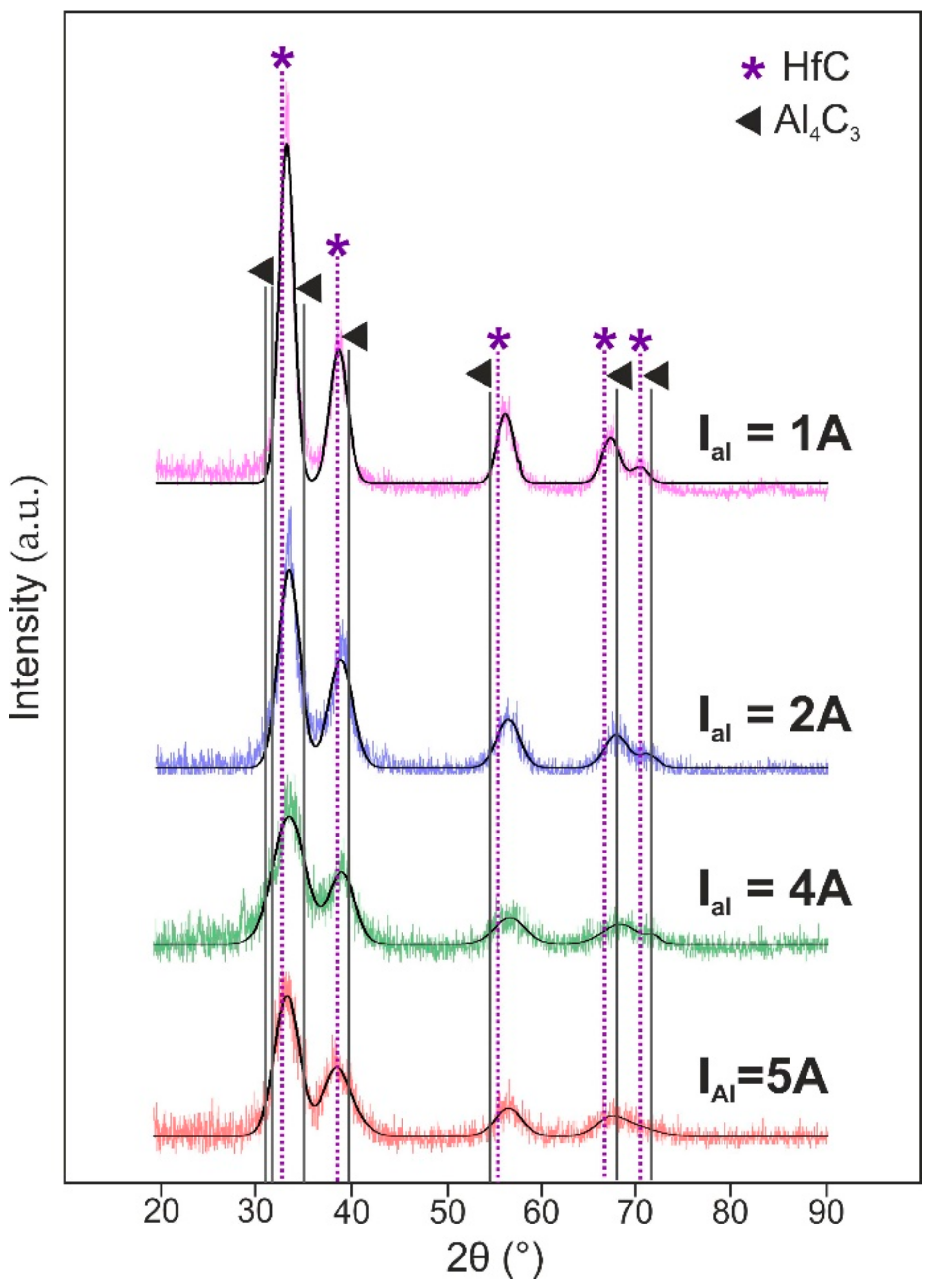
In order to determine the cause of Hf–Al–C system microstructure transition, XRD analysis was used. The value of full width at half maximum (FWHM) for deposited films, measured for the main peak centered at 2θ = 31°, was 1.8° (I
Al = 1 A), 2.6° (I
Al = 2 A), 3.07° (I
Al = 4 A) and 3.9° (I
Al = 5 A). An increase of the FWHM value for the Hf–Al–C films deposited at higher Al discharge currents indicates a decrease in the size of the coherent scattering region, which partly confirms the films microstructure transition, detected by SEM. As can be seen from
Figure 2, all coatings show similar XRD spectra, attributed to the reflections of fcc-HfC, regardless of the Al target current. No Al
4C
3, Al
3Hf or other Al-containing structures can be detected. In addition, contrary to [
9] the Hf–Al–C film does not form such layered structures as Hf
2AlC, Hf
3AlC
2 or Hf
3Al
3C
5. Despite the fact that there are no characteristic peaks for Hf–Al–C or Hf–Al compounds on the X-ray diffraction patterns, the presence of aluminum in the films, detected by EDX analysis, might indicate a non-stoichiometric composition of the film.
Since HfC and TiC show similar physicochemical behavior, we suggest that the arrangement of Al in the crystal lattice of the Hf–Al–C system will be similar to that for the Ti–Al–C system. As described in [
12], the synthesized film could consist of a solid solution of Al in non-stoichiometric fcc–HfC and is associated with insufficient sample temperature during the deposition process to the MAX-phase structure formation. Besides, the HfC peaks shift and their asymmetry may also indicate the formation of a solid solution of Al in HfC.
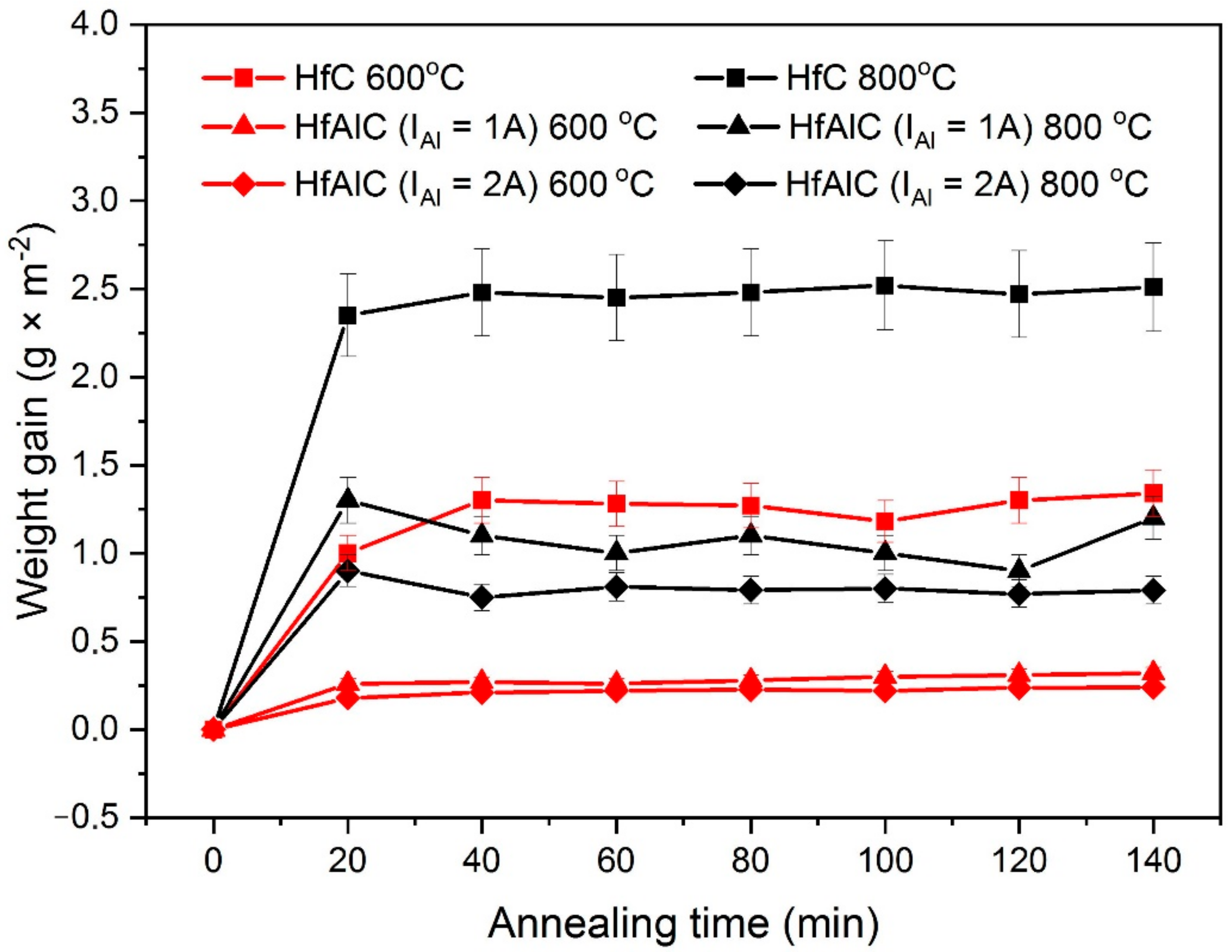
In order to evaluate the Al content influence on the oxidation resistance of the Hf–Al–C system, deposited films were annealed in muffle furnace in air atmosphere. To obtain accurate data, four samples of each type of coating were annealed. Because the oxidation resistance of porous materials is significantly lower than that for dense solids due to the facilitated oxygen penetration to the protected surface [
13], we performed oxidation tests for Hf–Al–C coatings with dense columnar structure. An alumina sample coated with 10 μm HfC was used as a control sample. The samples were annealed at 600 and 800 °C. The experimental results are presented in
Figure 3.
As can be seen in
Figure 3, all of the synthesized Hf–Al–C and HfC films exhibit parabolic oxidation kinetics for both 600 and 800 °C annealing regime, reaching a saturation at 30 min after the annealing start. We attribute this saturation to the formation of the protective amorphous Al
2O
3 on the top of Hf–Al–C film and HfO
2 on the top of HfC film. Furthermore, regardless of the annealing temperature, the Hf–Al–C system shows improved oxidation resistance compared to the HfC film. Thus, the HfC film annealed at 600 °C shows the average weight gain value of 1.53 g·m
−2 whereas the Hf–Al–C (I
Al = 1 A) film with a minimal addition of Al, annealed at a higher temperature (800 °C;), had an average weight gain value of 1.05 g·m
−2. The obtained experimental data show that in the case of annealing at 600 °C, the Hf–Al–C (I
Al = 1 A, Al conc. 5.6 at.%) and Hf–Al–C (I
Al = 2A, Al conc. 9.2 at.%) films show a decrease in the weight gain value by 4.3 and 5.7 times in relation to the sample with a HfC coating, respectively. At the annealing temperature of 800 °C, the weight gain value for the same samples decreases by 2.4 and 3.2 times, respectively.
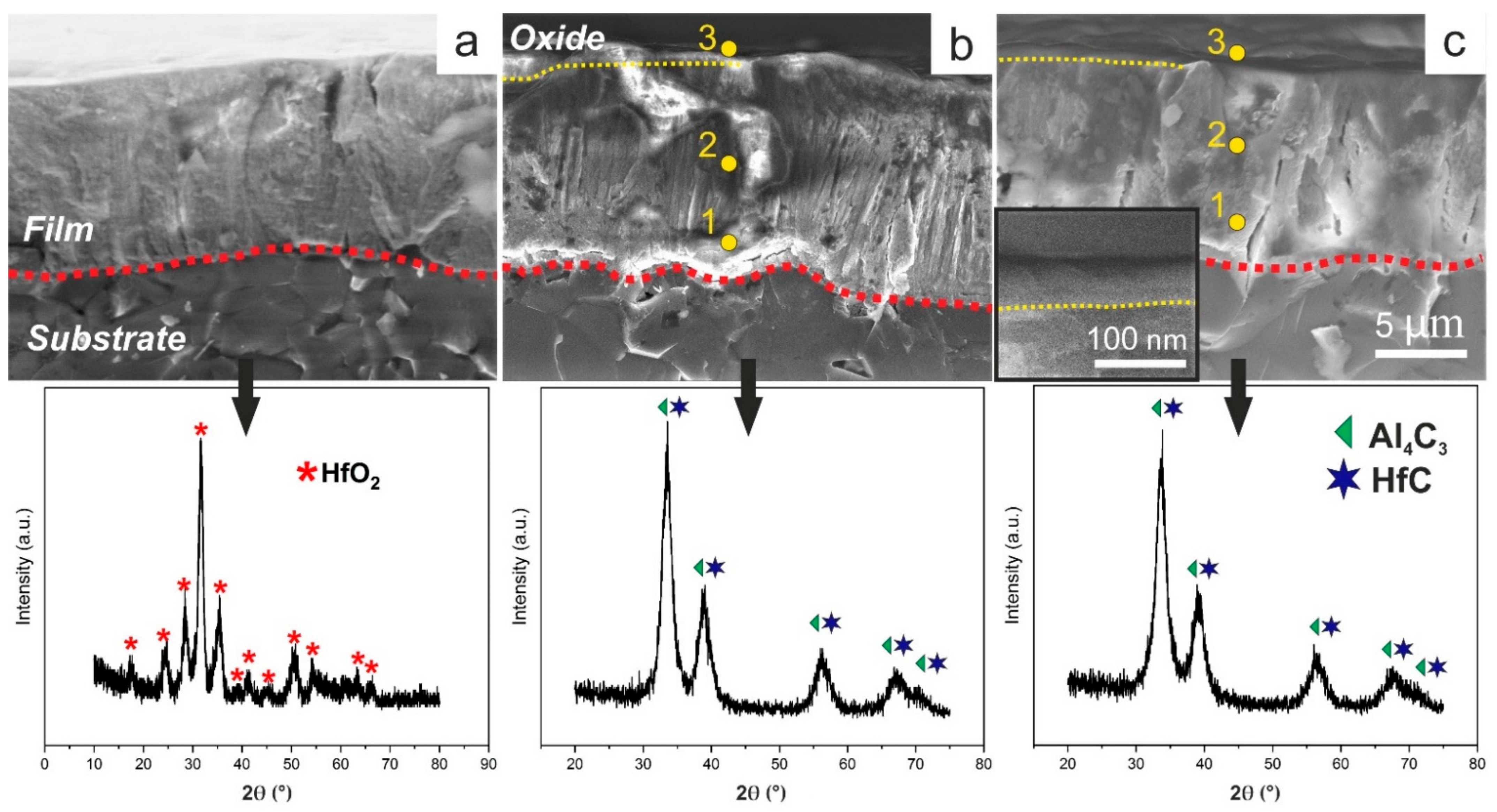
In order to evaluate the formation of the protective layer after the annealing test all samples were analyzed using SEM, XRD, and EDX (
Figure 4).
As can be seen in
Figure 4a, after annealing for 140 min at 800 °C, the HfC film completely transforms into monoclinic HfO
2 (P21/c), JCPDS 43-1017 standard). Besides, one can detect a clearly visible film structure change after the annealing test. Despite the fact that X-rays were carried out in the grazing beam mode, no changes in the phase composition of the coatings were recorded for both Hf–Al–C systems. As can be seen from
Figure 4b,c, XRD patterns of Hf–Al–C films completely match with XRD patterns of the same coatings before annealing. No displacements of the peak centers, as well as their broadening, can be found. This fact supports the suggestion that the formation of the protective amorphous Al
2O
3 on the top of Hf–Al–C film protects it from further oxidation. While X-ray diffraction analysis did not show any changes in the Hf–Al–C coatings after the annealing test, the SEM micrographs of both films showed the formation of a thin surface layer with a dense homogeneous structure without pronounced crystallinity, different from that of the reference HfC coating (inset of
Figure 4c, the part above the yellow dotted line). The thickness of this layer is ~70 nm irrespective of the Al concentration in Hf–Al–C films. In order to determine the composition of the surface layer formed in Hf–Al–C systems, an EDX analysis was performed. It was found that near the substrate-coating interface, as well as in the central part of the coating, oxygen is completely absent (
Figure 4b,c, yellow dots 1,2). The elemental composition of the Hf–Al–C film (I
Al = 1 A) at these points is the same and amounted to 49.5 at.% C, 44.9 at.% Hf and 5.5 at.% Al. Elemental composition of the Hf–Al–C film (I
Al = 2 A) at the same points was 47.7 at.% C, 43.2 at.% Hf and 9.1 at.% Al. EDX analysis of the surface layer of both Hf–Al–C coatings (
Figure 4b,c, point 3) showed the presence of the oxygen content in the amount of 22.77 and 18.62 at.%, for Hf–Al–C (I
Al = 1 A) and Hf–Al–C (I
Al = 2 A) films, respectively.
Based on the analytical data, the oxidation test results could be explained by the difference in the oxidation mechanisms of the coatings. In the case of HfC, hafnium oxide formed on the film surface does not reduce the oxygen diffusion rate due to the high conductivity of HfO
2 to O ions [
14], which results in complete oxidation of the hafnium carbide film. In addition, a formation of gaseous CO and CO
2 during the film oxidation leads to the growth of porous structure and causes a sample mass gain [
4,
15]. Contrary to HfO
2, Al
2O
3 has a dense amorphous structure and one of the lowest oxygen permeabilities [
4,
7]. Thereby, at the initial stage of the Hf–Al–C film annealing process, Al
2O
3 is formed. Alumina acts as an oxygen diffusion barrier and blocks a further oxidation of Hf–Al–C. The obtained data partially correlate with the values for the bulk sample Hf–Al–C sintered by the hot pressing method during annealing at 900 °C [
16].


