1. Introduction
Surgical tools can be divided according to their function into cutting, stabbing, grasping, holding, and those used for special purposes. Each surgical instrument consists of a working part, a gripping part, and a joint. Its construction may also include special elements [
1,
2,
3]. The working part is an active element that has direct contact with tissues or auxiliary materials. It may be categorized as blunt or sharp [
4]. The task of the blunt parts is the bloodless drawing, holding, and expansion of the operated tissues. The working parts of blunt instruments may be smooth (e.g., surgical hooks) or have incisions (e.g., forceps) to facilitate better tissue grasping. The sharp parts are used to perform bloody separation of the tissues during the procedure by means of cutting, drilling, scraping, or biting off. Examples of sharp tools are surgical knives, saws, and bone cutting forceps [
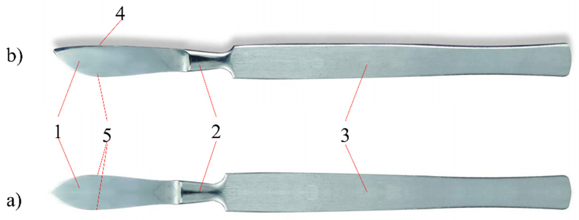
5]. Various types of knives designed for cutting soft tissues belong to the group of single-blade flat tools.
Figure 1 shows the structure of a surgical knife called a scalpel [
1].
The most widely used surgical knives are ventral and pointed scalpels. A cutting edge with a variable radius and a flat back are characteristic of ventral scalpels; sharp-pointed scalpels are characterized by a blade structure symmetrical to the axis of the knife. Today, surgical knives with replaceable blades are often used. This solution allows the use of disposable blades with different geometric features. Handles of surgical knives are made of X20Cr13 cold-worked stainless steel [
1,
2,
3,
4,
5].
Materials for surgical instruments must meet the criterion of corrosion resistance in the tissue environment and body fluids, when in contact with the drugs used, and when in contact with disinfectants used during sterilization. In addition, the material should ensure the transfer of stresses occurring during use, while maintaining functional features—the mechanical properties and the usable form of the tool [
6,
7]. The materials currently used for the components of medical instruments include some types of steel from corrosion-resistant alloy steels. Due to the relatively short period of contact of the tools with body fluids and the tissue environment, the requirements for the corrosion resistance of plastics are not as stringent as in the case of metal biomaterials for implants. Steels for surgical instruments belong to the group of high-alloy steels resistant to corrosion and have been divided into three groups [
1,
2,
3,
4]: austenitic, ferritic, and martensitic. These steels contain nickel, chromium, and manganese as the main alloying elements, and molybdenum, silicon, and vanadium as other alloying elements [
6,
7,
8,
9].
One of the methods of reducing wear and increasing corrosion resistance is to modify the surface layer of tool elements by depositing thin coatings on them [
10]. Parameters such as the structure and chemical composition, hardness and brittleness, roughness, coefficient of thermal expansion of the coating in relation to the base material, and the value of the coefficient of friction or adhesion in relation to the base determine the quality of the usable coating on the blade. Among the methods of depositing coatings, the physical vapor deposition (PVD) method is of great importance in practice. Its main advantages include the low temperature of the process, thanks to which it is possible to deposit coatings on steel elements after hardening without fear of its tempering or loss of properties. Functional coatings are also often deposited by chemical vapor deposition (CVD) methods [
11,
12]. The search for a method that would combine good layer adhesion and not too high process temperatures, enabling the coating of hardened substrates, led to the development of the atomic layer deposition (ALD) method, considered a variant of the CVD method. The ALD method is derived directly from metalorganic chemical vapor deposition (MOCVD) where highly reactive organometallic compounds are also used. The difference is that in the case of MOCVD, the reactants are delivered simultaneously, while in the case of ALD, the precursors are delivered separately to the chamber, and the entire reaction takes place only on the surface of the substrate. The ALD method is based on the controlled application of layers with a thickness of a few nanometers. In each cycle, exactly one monolayer is deposited on the substrate, so it gives full nanometric control over the layer produced. Precursors, called reactants, can be solid, liquid, or gaseous. ALD methods often use similar reagents to CVD and MOCVD methods [
13]. Precursors are fed alternately to the reaction chamber, which makes it possible to use even very reactive precursors without fear of chemical reaction before reaching the substrate. The temperature range of the ALD process is up to 500 °C. The undoubted advantages of the ALD method include the possibility of the even coating of objects, even of very complex shapes, and the uniformity of the chemical composition of the produced layer. Using the ALD method, it is possible to deposit single-component as well as multi-component layers [
14]. The ALD method is widely used to deposit various materials, such as metals and their oxides and nitrides, creating defect-free coatings with a thickness of several dozen nanometers. In addition, ALD enables the deposition of excellent quality coatings and uniform layer thickness, even on substrates with complex shapes. The ALD technique enables the requirements for high mechanical and anti-corrosion properties, chemical and thermal resistance and biocompatibility of tools when used in medicine, even where the coating is applied to a relatively delicate substrate [
12,
13,
14].
The coatings applied to the surgical instruments play a very important role in the health of the patient. Not only do they protect the material from which the tool is made against corrosion, but also avoid damage to tissues by reducing friction [
15,
16,
17]. They reduce the risk of inflammation and infection. In addition, they enable the work of electric tools, e.g., toothed wheels in dental drills, to work without grease. Anti-reflective, wear-resistant black coatings are applied to the bone scissors. Bone repositioning tools use anti-reflective coatings for increased wear resistance. Wear-resistant ceramic coatings on reamers and bone drill bits provide long-lasting edge sharpness. Coatings applied to dental screws allow for better adjustment, reduced torque during assembly, and a greater holding force for the screws after assembly. Surgical instrument coatings increase scratch resistance, are anti-reflective and have antibacterial properties to reduce the risk of infection developing during surgery [
17,
18,
19]. Coated bone saws have oil-free lubrication, which allows the tool to work properly at high speed, even at low temperatures. In the case of surgical instruments, coatings such as nitrides (TiN), carbons (TiC) and metal oxides (TiO
2, Al
2O
3, Cr
2O
3, ZrO
2) are of great importance. One interesting solution is to enhance the cutting properties of the various blades by coating them with Zr- and Fe-based thin film metallic glasses. Another interesting solution is the use of diamond-like carbon (DLC). It is a metastable amorphous carbon material with significant sp
3 bonding; DLC shares some of the properties of diamond, such as high hardness, high elastic modulus, and chemical inertness, but it can be produced much more cheaply [
20,
21,
22,
23].
The aim of the study was to deposit ALD zinc oxide thin films on the blades of surgical scalpels and to investigate the structure and adhesion of the layers deposited. PVD and CVD methods have been the most frequently reported [
17,
18,
19,
20,
21,
22,
23]; however, the ALD method is characterized by high accuracy in controlling the thickness of layers and enables the entire element to be covered, even if it is of a complex shape. The antibacterial properties of ZnO have been applied in medicine for decades, as evidenced by a relatively wide range of solutions available on the market. However, no reports of its use on scalpels have been identified. Therefore, the structure of the deposited thin films was studied using a Raman spectrometer and their surface topography investigated using atomic force microscopy and scanning electron microscopy. The adhesion of the deposited thin films and corrosion resistance were also tested. All the tests were carried out to verify the usability of these coatings for use in surgical scalpels.
2. Material Descriptions and Research Methodology
The sterile blades of disposable surgical scalpels (InterMed Company, Shenzhen, China) made of surgical steel were coated with ZnO thin films using the atomic layer deposition method (Picosun R 200 System) (Espoo, Finland). Diethyl zinc (C2H5)2Zn was used as the zinc oxide precursor, which reacted with deionized water, allowing the deposition of thin films. It is a highly self-inflammatory and reactive compound. Chemical reactions in the process of atomic layer deposition were thermally supported. The thin films were deposited in a reaction chamber (growth chamber), into which precursors were cyclically introduced. The temperature in the chamber was 200 °C. The reagents’ dosing time was equal to 0.1 s. Nitrogen was used as a transporting and purging gas (to clean the chamber between dosing cycles). The flow of nitrogen was equal to 200 sccm. The purging time was 4 s for diethylzinc and 5 s for water. Cycles of 500, 1000, and 1500 were applied.
The surface morphology of the analyzed samples was evaluated by the atomic force microscope (XE-100, Park Systems, Suwon, South Korea). The study was conducted in a non-contact mode, in areas of 10 × 10 µm2. The cantilever vibration frequency was 300 kHz, and the recorded test results were developed in the Park Systems XEI 4.3.0 program. The 2D and 3D images were recorded and basic roughness parameters were calculated. Furthermore, scanning electron microscope (SEM) images were taken with a Zeiss Supra 35 (Zeiss, Thornwood, NY, USA). The accelerating voltage was 3–5 kV. To obtain images of the surface topography, the secondary electron detector (by the in-lens detector) (Zeiss, Thornwood, NY, USA). was used. Qualitative studies of chemical composition were also performed using energy-dispersive spectrometry (EDS). Further structural testing of deposited thin films was performed using an inVia Reflex Raman spectrometer (Renishaw, New Mills, UK), equipped with an Arion laser with a 514.5 nm length for a spectral range of 50–3100 cm−1. The adhesion of ZnO thin films to the assessed surgical steel was evaluated using a micro-scratch test method applying open platform (CSM Instruments, Needham, MA 02494, USA). During the test, a Rockwell diamond cone with a gradual increase in the indenter’s load was used to make a scratch. The critical force was determined as the minimum normal force that caused the loss of adhesion of the tested coating to the substrate. Changes in acoustic emission, friction force, and friction coefficient, as well as microscopic observation, were the parameters required to evaluate the critical force, Lc. The tests were carried out with the loading force increasing in the range Fc = 0.03–30 N. The following operating parameters were applied: scratch length l = 3 mm; loading rate vs = 10 N/min; and table speed vt = 10 mm/min.
Corrosion tests were performed in a controlled environment (3% NaCl solution, 25 °C). The measuring system consisted of an Autolab 302 N potentiostat (Metrohm AG, Herisau, Switzerland) equipped with a three-electrode system. The experiments were conducted with the use of NOVA software. The following three electrodes were used: a saturated calomel electrode (SCE) as a reference; a platinum counter electrode; and the material tested as a working electrode. Corrosion resistance was assessed by recording the change in open circuit potential (EOCP) versus SCE. The corrosion potential (Ecorr) and the corrosion current density (jcorr) were also determined by the Tafel extrapolation method. The samples were measured after stabilization of the open circuit potential for 1800 s and a scan rate of 1 mV·s−1.
3. Results and Discussion
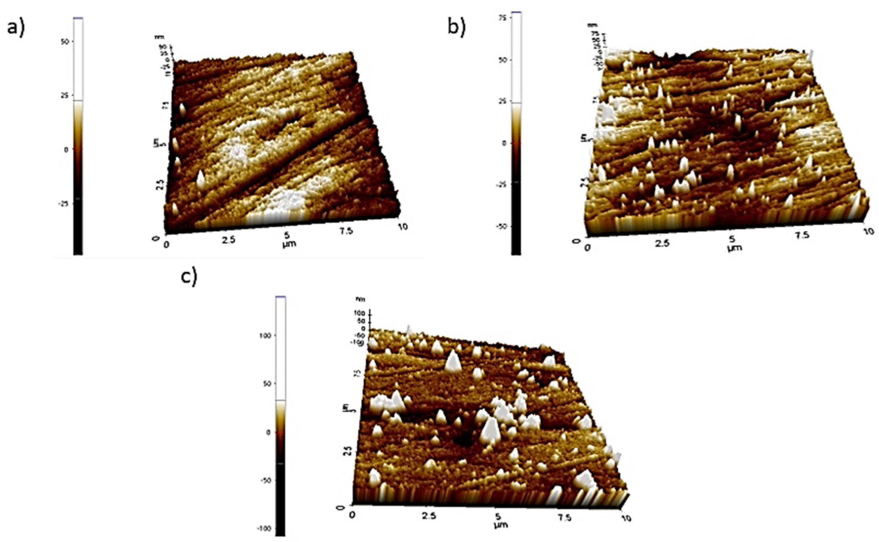
The topography of the deposited thin films on the surfaces of the scalpel blades is shown in
Figure 2 and
Figure 3. The effect of the number of cycles performed on the surface morphology of the deposited thin films can be seen. The deposited thin film with fewer cycles consists of evenly distributed, small, spherical clusters of atoms. The greater the number of cycles, the larger and more elongated the clusters of atoms. Along with the increase in the number of cycles from 1000 to 1500, the roughness parameters slightly increased.
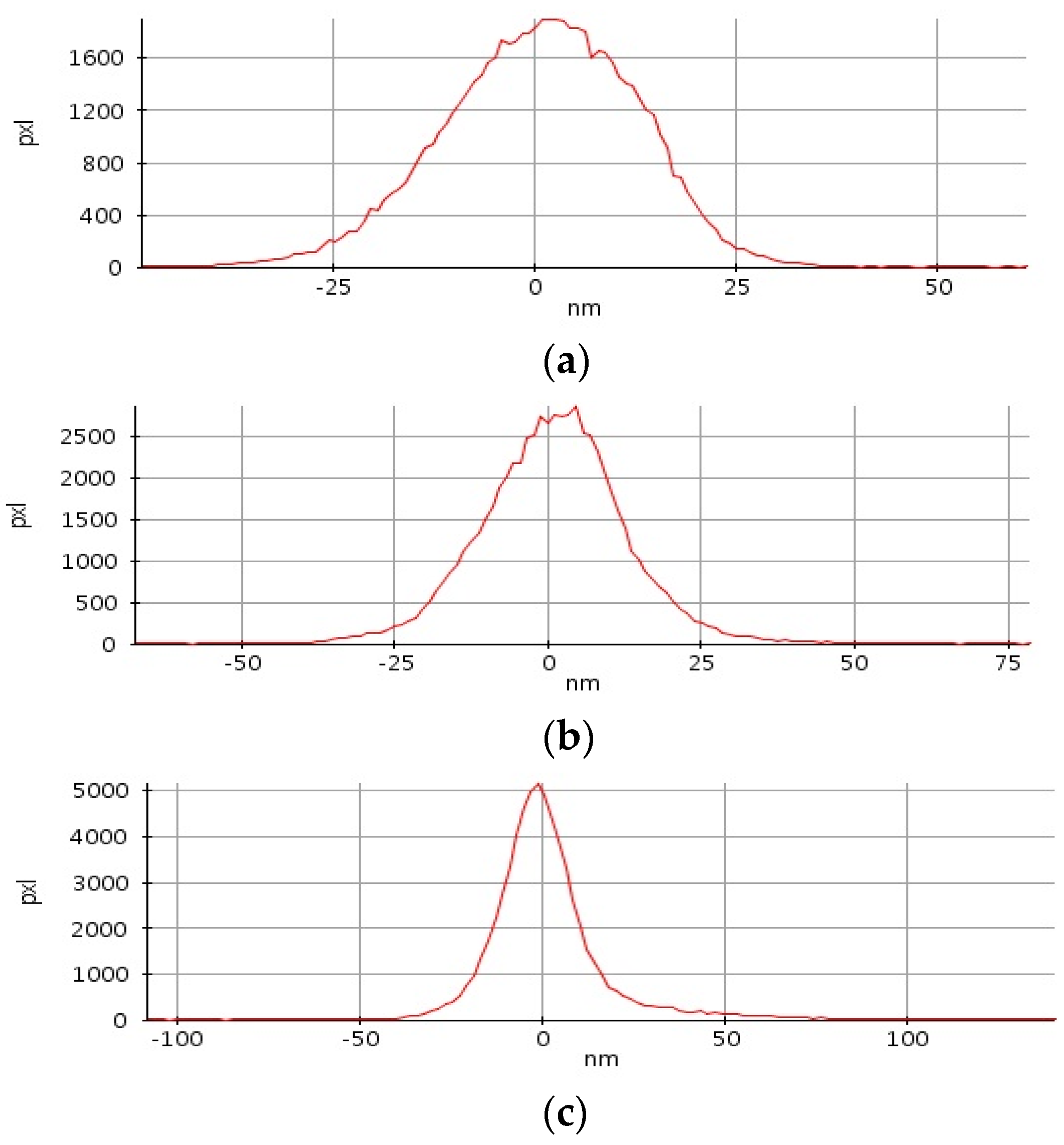
The histograms prepared on the basis of the AFM images allow a statistical analysis of the surface roughness (
Figure 4). An inequality of the same value is assigned to a specific pixel and counted. On this basis, it can be concluded how often individual inequalities occur and what sizes they dominate. When analyzing the histograms of the frequency of unevenness on the surface, the smallest differences occur in the thin film deposited after 500 cycles, which correlates with the analysis of surface topography images and the calculated roughness parameters. For the thin films deposited after 500 and 1000 cycles, inequalities not exceeding 25 nm are dominant, and the maximum unevenness is, respectively, 60.83 and 78.38 nm. For the layer deposited after 1500 cycles, inequalities not exceeding 50 nm dominate, and the greatest irregularity is 139.89 nm.
Table 1 summarizes the roughness values of
Ra and
Rq as well as the values of maximum elevations for three samples deposited with the ALD method with a different number of cycles.
Ra is the arithmetic mean of the deviation from the assessed profile, expressed by the formula:
Rq—The root mean square, given by the formula:
The samples deposited after 500 and 1000 cycles have similar roughness parameters. The thin film deposited after 1500 cycles is slightly rougher. As the number of cycles increased from 1000 to 1500, the roughness parameters increased.
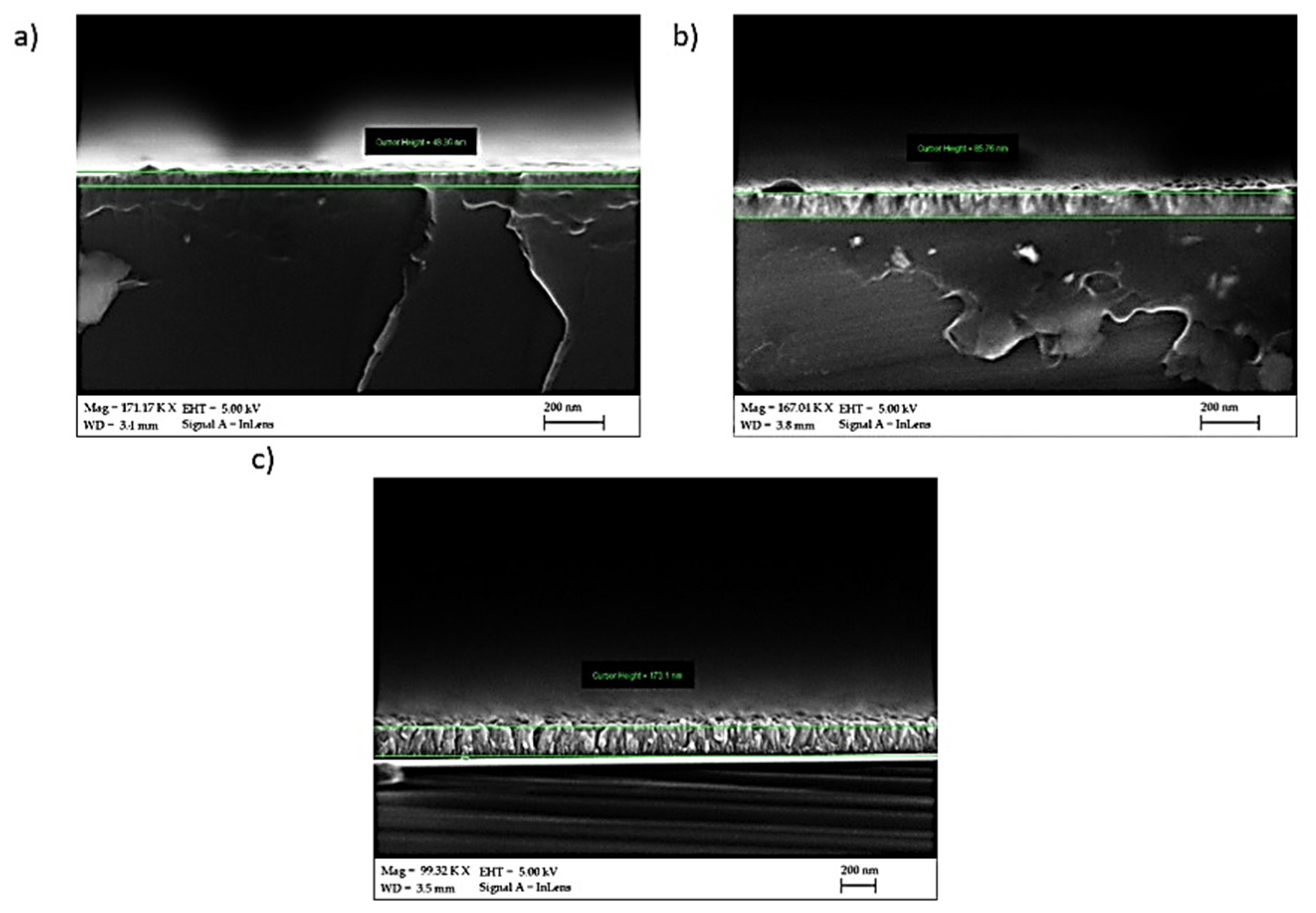
For samples deposited at 200 °C, examination in a scanning electron microscope showed that grains were characterized by an elongated shape. The grains were distributed randomly with no dominant direction of their arrangement; the grain size was irregular (
Figure 5). The morphology of ZnO thin films deposited by ALD is homogeneous and uniform, which is also confirmed by the images of breakthroughs (
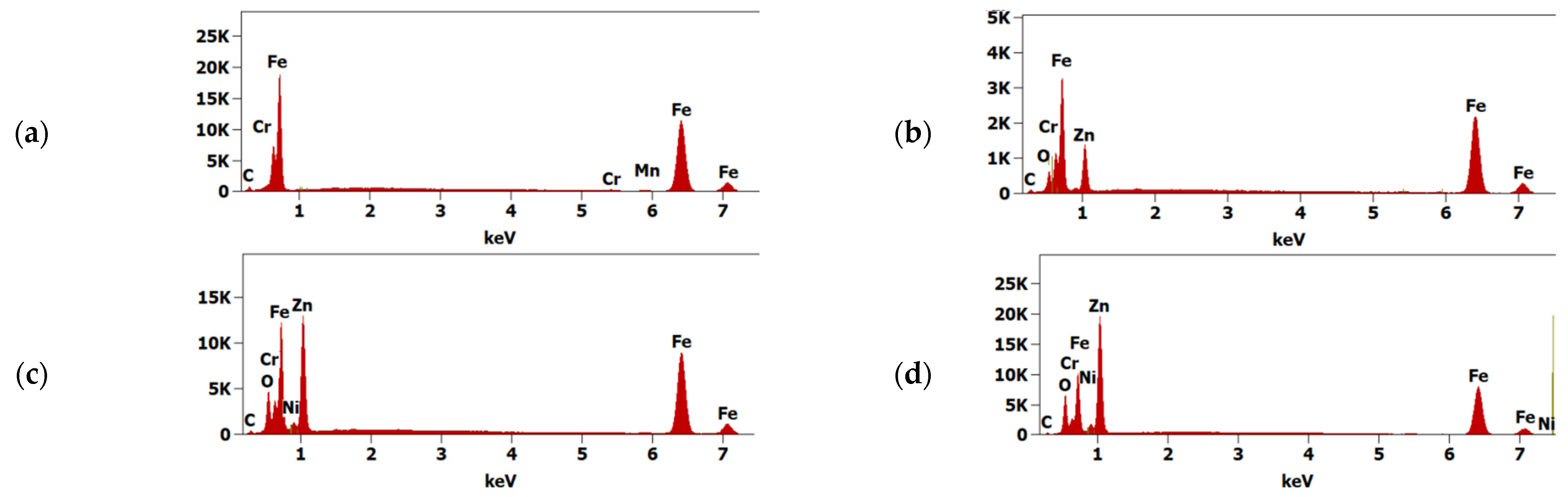
Figure 6). The surface does not show any discontinuities, cracks, pores, or defects. The EDS tests confirmed that the scalpels used for the tests are made of chromium-nickel stainless steel with a low carbon content (
Figure 7). In further analysis, zinc and oxygen from the ZnO coating were also identified. As the number of cycles increased (i.e., the thickness of the layer), the intensity of the zinc-derived peak increased.
Raman spectrometry is a helpful tool for evaluating the quality of a prepared thin film. Raman spectra make it possible to identify thin films and study their structure.
Figure 8 shows a Raman spectrum of the ZnO thin films excited with an Ar ion laser at 514.5 nm. All observed spectroscopic peaks can be assigned to a wurzite-type structure in all the prepared ZnO thin films. The wurtzite-type ZnO belongs to the space group C46υ with two formula units per cell. In accordance with the group theory, optical modes which exist in a ZnO wurtzite-type are given Γ
opt = A
1 + 2B
2 + E
1 + 2E
2. In Raman spectra, according to the selection rule, the B
1 modes are inactive. As predicted by group theory, the Raman active modes are A
1, E
1, and 2E
2. The phonons of A
1 and E
1 symmetry modes are polar phonons with different frequencies for the transverse-optical (TO) and longitudinal-optical (LO) vibrations. The nonpolar and Raman active phonon modes with symmetry E
2 have two frequencies, high and low: E
2H—associated with oxygen atoms and E
2L—associated with Zn sublattice. The A
1(LO) of ZnO thin films deposited by the ALD method after 1500 cycles were recorded at 575 cm
−1. The E
2L and E
2H of the ZnO thin films were recorded at 101 and 436 cm
−1, respectively. The peaks recorded at 332, 659, and 1150 cm
–1 are from multi-phonon modes, which are assigned to the E
2H-E
2L, 3E
2H-E
2L, A
1(TO)+E
1(TO)+E
2L, respectively.
Irrespective of the number of ALD cycles, in all recorded Raman spectra, the structure of the ZnO wurtzite-type was identified. There were slight shifts and extensions of some of the recorded peaks in the Raman spectra, which may indicate differences in the dimensions of ZnO crystals depending on the number of ALD cycles.
The adhesion of ZnO thin films to the assessed surgical steel was evaluated using a micro-scratch test method. The crack (Lc
1) was registered at a load of 0.06 N for 500 cycles, 1.89 N for 1000 cycles, and 0.16 N for 1500 cycles. The first delaminations (Lc
2) registered on samples with 500 cycles at a load of 2.82 N, on samples with 1000 cycles at a load of 3.46 N, and on samples with 1500 cycles at a load of 5.38 N. The thin film deposited after 500 cycles was completely damaged at a load of 6.06 N. It follows that samples deposited following 500 cycles had the weakest adhesion. Samples deposited after 100 cycles had slightly better adhesion. The test results also showed that the layers deposited at 500 and 1500 cycles were more brittle than the layers deposited after 1000 cycles. However, the authors did not note any dependencies in the structure of the layer. This may be due to stresses in the layer itself. Confirmation of this requires further XRD and HRTEM structural studies. Despite this, the sample deposited after 1500 cycles had the best adhesion to the surgical steel substrate (
Table 2). Examples of the types of damage recorded during the scratch test for the ZnO layer deposited after 1500 cycles are shown in
Figure 9.
The open circuit potential for the samples after 1000 and 1500 cycles stabilized at approximately −0.47 V vs. SCE (
Figure 10). For uncoated samples and samples after 500 cycles, the potential drop is sharper. This may indicate insufficient thickness of the thin film deposited after 500 cycles to stop the corrosion. Polarization tests also showed significant differences between the samples deposited after 500 and 1000 cycles (
Figure 11). Of note is the significantly lower potency value for the sample deposited after 500 cycles compared to the reference sample. This is probably due to the influence of temperature during the application process and insufficient thickness of the film. Samples of 1000 and 1500 cycles have the same E
pit potential, but in the case of a sample after a greater number of cycles, the current density drops significantly. This is probably due to the thickness of the thin film, which translates into a reduction in conductivity. Based on the tests carried out, it can be concluded that too thin ZnO thin film (500 cycles) deposited with the described technique may reduce the corrosion resistance. The greater thickness of the thin film improves the resistance of the samples under the tested conditions.
There is a noticeable effect of the thickness of the ZnO layer on the reduction of corrosion processes, with a decrease in the Jcorr value from 38 mA/cm
2 for the uncovered sample to 1 mA/cm
2 for the sample given 1500 cycles (
Table 3). Additionally, after obtaining the appropriate thickness, the ZnO layer stabilizes the corrosion potential at a higher level, which also limits the speed of corrosion processes. In the discussed case, this corresponds to the thickness of the coating achieved after about 1000 cycles and a potential of −0.46 V.


