1. Introduction
The most used method of obtaining the pressure map on the surface of a model involves drilling small perpendicular holes into the model, which are connected to pressure transducers. However, this method has some disadvantages; the taps can influence the air flow, and the measurements are made punctually, and it is necessary to interpolate the data for a complete image of the pressure. A solution to overcome these problems is by using a coating that is sensitive to pressure. This can be achieved with a photoluminescent dye. With this technique, the measurement of the airflow pressure is possible for the entire model, not just at certain points, so a better spatial resolution can be seen and irregularities are easily observed. Moreover, an important advantage is that this method is non-invasive.
The visualization of air pressure distributions on surfaces gained attention with the growth of the aerospace industry even though the technology (oxygen sensitivity) was first explored for medicine. In most cases, aerodynamic tests are conducted in wind tunnels. Pressure-sensitive paint techniques are studied and refined by all major aerospace research centers in the world such as DLR (Germany), ONERA (France), JAXA (Japan), and NASA (USA). Through a special technique and the application of appropriate optical systems, the static pressure values can be measured on the surface of the model inside the test installation (subsonic or transonic wind tunnels), so that the flow phenomena can be evaluated quantitatively.
Usually, a PSP coating consists of dye molecules, also named luminophore, and a binder that is permeable to oxygen. An important component to obtain a fast-response PSP is a porous binder, which allows the rapid diffusion of oxygen, and thus a rapid response. A porous binder can be achieved by the following two methods: by suspending the ceramic particles (in this paper, TiO
2) and a small amount of polymer in a suitable solvent and spraying the resulting mixture on the surface of the model to form a porous layer [
1,
2], or by increasing the porosity of the model surface by an anodizing process [
3]. As Lorenz Fischer [
4] described in his paper, oxygen permeability is the most important characteristic for which polymers are chosen, and the permeability coefficient can be expressed as follows:
Scroggin et al. [
2] also developed polymer/ceramic paints, based on titanium dioxide (TiO
2) particles in a small amount of polymer. They used platinum octaethylporphyrin (PtOEP) as luminophore, dissolved in a solvent and applied to the polymer/ceramic binder through a dipping process. The PtOEP luminophore exhibited greater pressure sensitivity. The response times of the paint formulation were of the order of 60 ms.
In the literature [
5,
6,
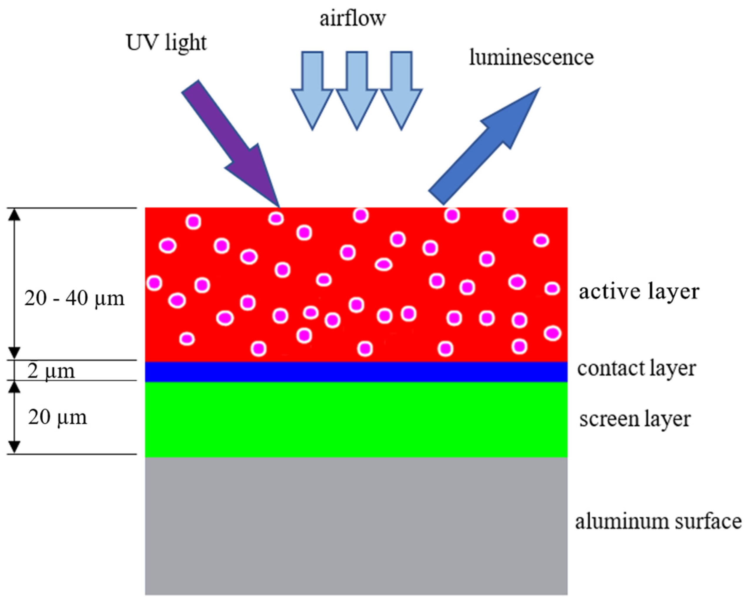
7], studies have shown that it is necessary to deposit at least two layers of paint. The first layer has the role of screening, and the second layer contains light-sensitive dye particles. Sometimes, a third layer is added to achieve better adhesion between the first two layers or for a better temperature control. As mentioned above, recent studies have shown that there is a correlation between the total thickness of the layers, which must be between 30 and 60 μm, and the permeability coefficient. In this paper, studies were conducted on the thickness of the deposited layers, and the need for a bonding layer. Research has also been carried out on the preparation of the surface of the model in order to increase the adhesion of the pressure-sensitive paint layers.
This paper describes the development of a new technology for obtaining pressure-sensitive paint, in laboratory conditions, as an advanced measurement technique, suitable for unstable pressure variations such as those in short duration wind tunnels. The paint is based on polystyrene granules and has a fast response time, which makes it suitable for a wide range of tests in conditions of wind flow variations. The key component of this technology is a porous binder based on ceramic particles of TiO2, which allows rapid oxygen diffusion and a new mixing technique that involves both sonication and magnetic mixing for a good dispersion of ceramic particles and obtaining a fast response of the coatings. For each mixing stage and for each layer deposited, the necessary time was granted to obtain the desired coatings. For the deposition of a single specimen with all the necessary layers, no less than 20 h of mixing were performed.
2. Materials and Methods
All materials used in the experimental stage (titanium dioxide, boron nitride, polystyrene, toluene, and PtOEP) were reagent-grade substances, purchased from Sigma-Aldrich, and are presented in
Table 1.
As mentioned earlier, the use of TiO2 ceramic particles in a mixture of polystyrene dissolved in toluene is an essential step for this study. This leads to a rapid diffusion of oxygen and a rapid response of the paint.
Toluene is a flammable liquid, employed as an organic solvent. It is widely used as a precursor for synthesizing benzene and as a solvent in the paint industry.
Nanoscale boron nitride possesses a number of material properties that increase its utility in coating applications, including wear resistance and better adhesion.
Platinum octaethylporphyrin is used as a fluorescent dye in the fabrication of polymer-based oxygen sensors. Its red emission is near 650 nm depending on host material and processing conditions.
The experimental study described in this paper is composed of several stages, which have significant effects on the final results, including substrate preparation and treatments as well as paint development and deposition techniques. In all stages of preparation of coatings, substrate, and painting the samples, the team was equipped with the necessary protective equipment.
2.1. Substrate Preparation
The support material chosen for the deposition of paint layers was aluminum AL6061 with a flat surface and low roughness. In order to determine the best possible adhesion of the paint layers on the surface of the support, three methods of substrate preparation were developed. The 2.5 mm thick plates were cut to a size of 7 cm × 7 cm over which pre-treatment was performed.
2.1.1. Pre-Treatment
Degreasing of aluminum plates was performed by wiping with charcoal soaked in 96% ethyl alcohol. The specimens were then allowed to dry in the ambient environment for 5 min. Pre-treatment was performed for all three methods of substrate preparation. The first method of depositing the paint layers was performed directly on the pretreated surface without any additional treatment.
2.1.2. Blasting
For a quick and efficient cleaning, the dry blasting method, with corundum, was chosen, using compressed air jet.
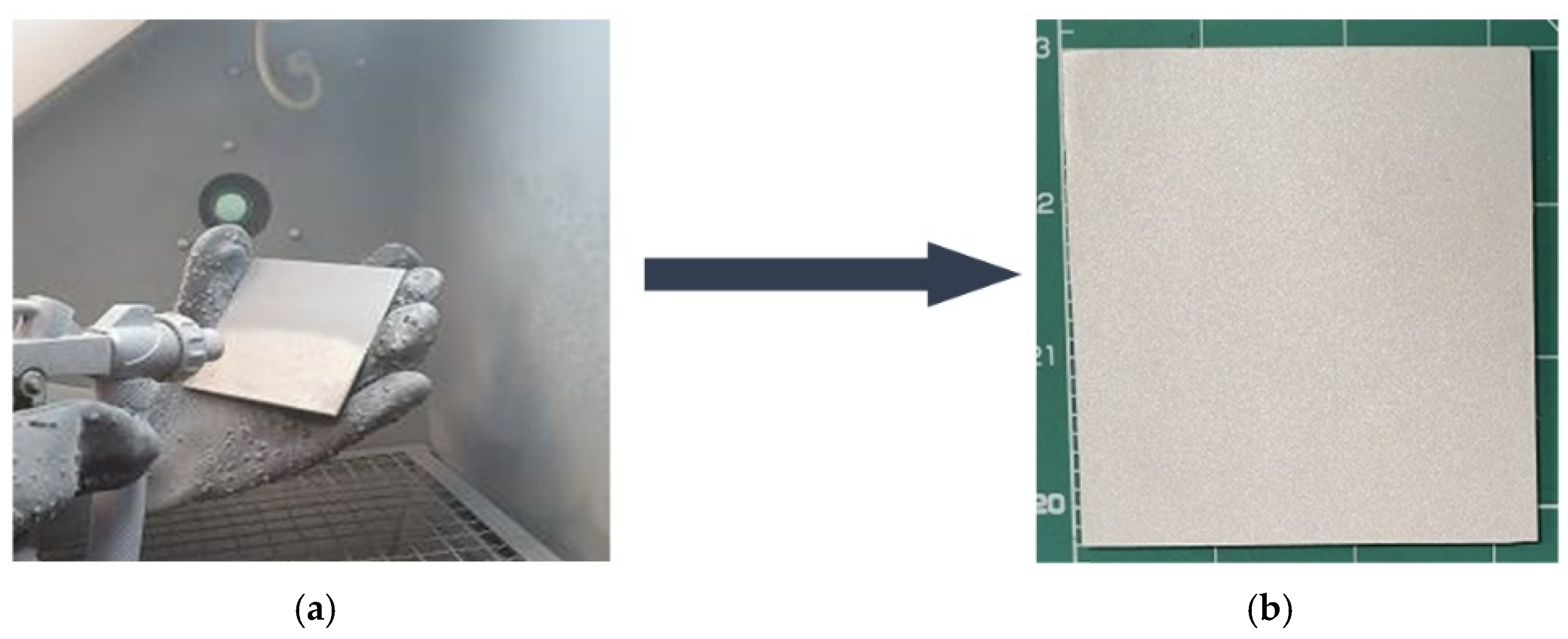
The blasting (
Figure 1a) was performed uniformly on the entire surface of the model with a horizontal movement from a distance of the gun of 5 cm from the test piece and an air pressure of 5 bar. After blasting (
Figure 1b), a jet of compressed air was used to remove the remaining corundum, and thus to obtain a clean surface with increased adhesion. The paint was applied immediately after sandblasting to avoid the growth of the oxide layer on the surface of the specimen.
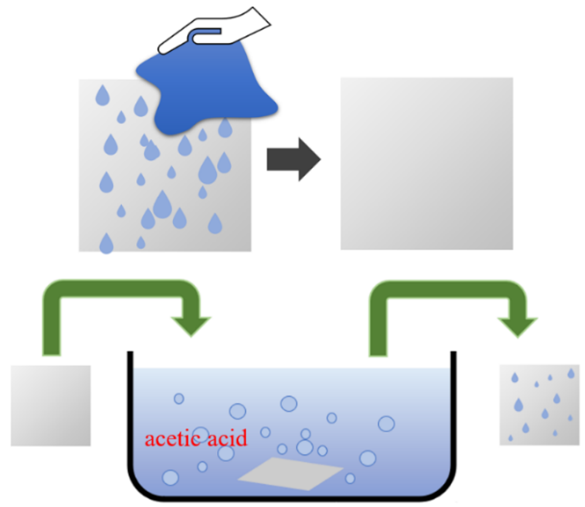
2.1.3. Chemical Attack
The last method of preparing the substrate was by chemical attack of the surface with 9% acetic acid (
Figure 2) for 16 h at a constant temperature (21–23 °C). After the procedure, the specimen was dried in ambient air for 10 min.
2.2. Paint Development
As mentioned before, the response time of the PSP is governed primarily by the thickness of the formulated paint and the diffusion coefficient of the binder. In order to obtain a high diffusion coefficient, we chose to suspend TiO2 particles in a small amount of polymer and to deposit the paint obtained on the surface of the model with the help of a paint gun. The sonication of the compounds was performed in several steps of 5 min each for a good dispersion of the ceramic particles, after which magnetic mixing was performed. Previous experimental trials were performed in order to establish the optimum polystyrene/toluene ratio, with the results indicating that using a ratio of ~0.9 g/15 mL and 1 g of TiO2 ensures obtaining uniform layers with increased porosity and a good distribution of the luminescent particles in the binder.
Tests were performed on the need for using the intermediate adhesion layer as shown in
Figure 3.
2.2.1. Screen Layer
The first layer, called the screen layer, is a mixture of polystyrene and TiO2 particles. This layer has high mirroring and facilitates optical reading by reflecting the unabsorbed incident light back through the polymer layer and emitting it to the imaging device, which is done from above. The process of obtaining the paint was performed in three stages. The first step was to dissolve the polystyrene particles in 15 mL of toluene for about 40 min. Sonication of TiO2 particles in toluene is performed until a good dispersion is obtained, and then magnetic mixing of the solution is carried out for 2 h and 30 min. The last stage was the mixing of the two compositions for 2 h. The obtained paint was applied with a spray gun in thin layers with a linear motion until a uniform coating was achieved, and then left to dry for 24 h.
2.2.2. Contact Layer
This layer is added in a thin film, up to 10 µm, when a better adhesion between the screen layer and active layer is needed. In order to observe the differences in adhesion, as well as to improve the degree of luminescence, a thin layer of the contact layer was used on one of the models.
Boron nitride was added to the polymer/toluene solution and then stirred magnetically for at least 2 h. The role of boron nitride is to control the heat dissipation accumulated during the measurements in order not to substantially influence the values obtained.
2.2.3. Active Layer
The active layer is the one that contains platinum octaethylporphyrin particles (PtOEP), thus becoming sensitive to pressure under ultraviolet (UV) lighting conditions. PtOEP is an oxygen-quenchable luminescent dye used as a fluorescent in the fabrication of polymer-based and silica-based oxygen sensors. To obtain the paint, 1 g of TiO2 was added to a solution of polystyrene dissolved in toluene and mixed magnetically for 2 h and 30 min. After a homogeneous solution with the desired viscosity was obtained, 0.02 g of PtOEP was added and mixed for another 2 h. The developed paint was spread over the other layers and left to dry in a light-protected environment for 24 h.
2.3. PSP Coatings Characterization
The developed paint and its adhesion to the used substrate were evaluated using macroscopical and microscopical techniques. The layered structure of the deposited paint was analyzed using an optical microscope (MEIJI 8520, MEIJI TECHNO CO., LTD, Saitama, Japan, equipped with video camera) that allows small magnification levels, which offer an overview of the cross-section of the samples. The coating morphology and homogeneity was investigated using scanning electron microscopy techniques (SEM Quanta 250, FEI Company, Hillsboro, OR, USA), which ensure high magnification levels, allowing the visualization of particles’ distribution and layer advanced architecture. The developed specimens were subjected to a pressure exposure test, using a 5 bar constant air jet directed on their surface from a distance of 30 cm under a 470 nm wavelength UV light exposure for 1 h.
3. Results
All the specimens obtained by the three methods of substrate preparation, as well as by the addition or not of the contact layer, were checked from the adhesion of the deposited layers point of view. Scratch tests were performed according to ASTM D3359 [
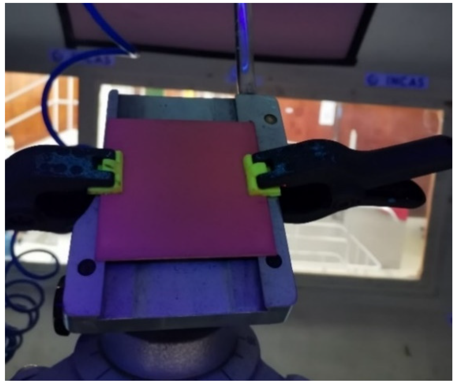
8] Method B by making six incisions having a distance of 2 mm from each other and another six at a 90° angle to the first ones. Substrates prepared only by wiping with ethyl alcohol or by chemical attack had an adhesion rating of 2B or less of the screen and contact deposited layers. Under these conditions of adhesion, the active layer was no longer deposited on these substrates. Regarding the screen layer and the contact layer on the substrate prepared by blasting, they have a 5B rating adhesion. The adhesion of the active paint to the contact layer was classified as 4B, according to the standard. Following the pressure test by air flow exposure and morphostructural analysis, the best solution was obtained by dry sandblasting the surface with corundum in a compressed air jet. In the case of the other two methods, the deposited layers yielded after the scratch test or without any test. This indicates that the aggressive mechanical type treatment of the substrate surface involving corundum sandblasting is more suitable than the mild chemical treatment involving low concentration acetic acid. The specimens that had good adhesion and withstood the scratch test were mounted in a fixed support and exposed to UV light while a constant jet of air of 5 bar was blown on the surface of the specimen from a distance of 30 cm, within an hour (
Figure 4). Photographic captures were taken every 5 min.
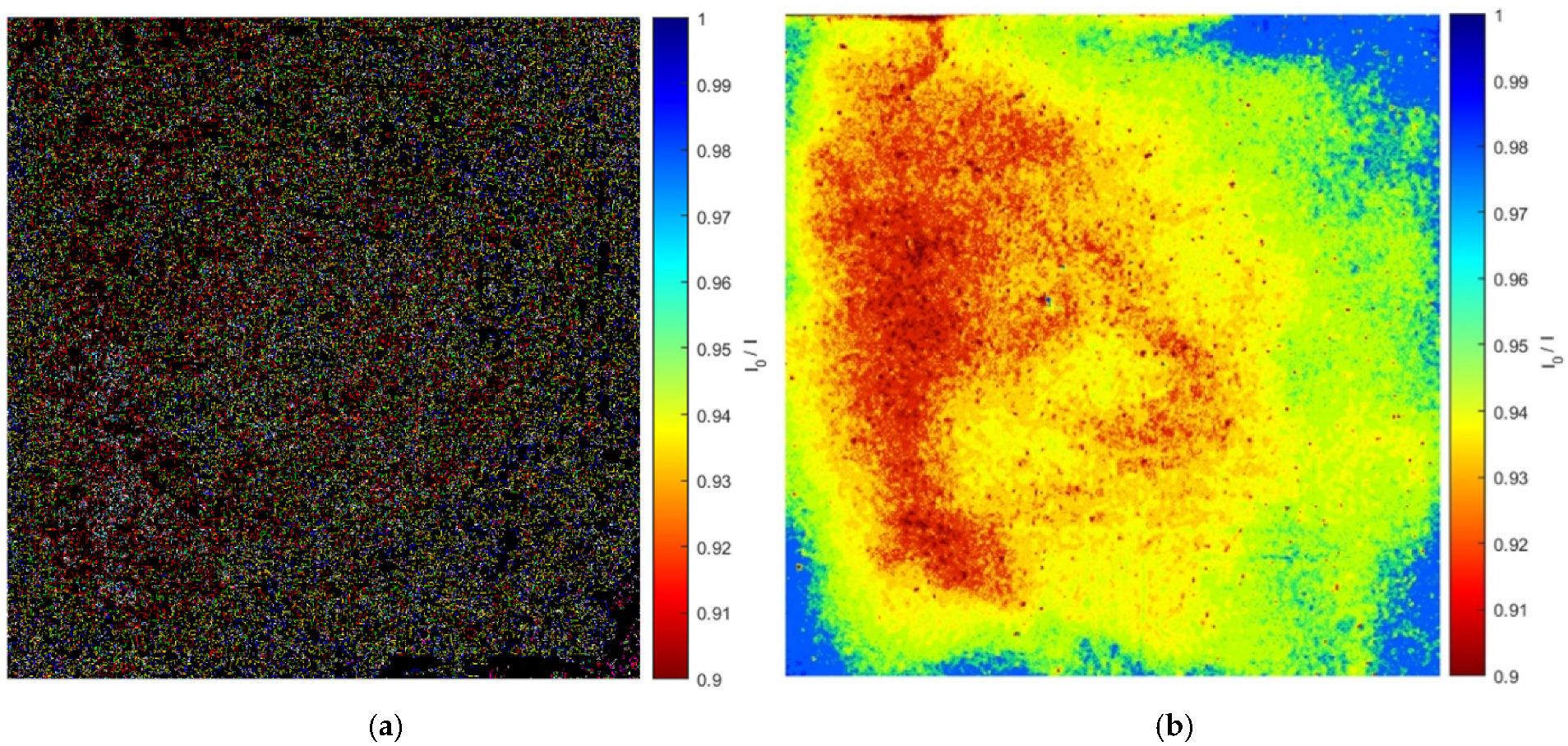
Figure 5 shows the images obtained during the process of applying pressure using air flow. The image is pseudo-colored to highlight the flow characteristics, so the low pressure is colored blue and the high pressure is represented by the color red. The color bar gives the relationship between the color shown on the model surface and the calculated pressure values based on the intensity values measured with PSP. This primary evaluation was performed in order to obtain preliminary guideline data of the pressure distribution on the specimen surface. For final formal data, specific calibration tests of the deposited PSP layers are required.
The images were processed using MATLAB software (
Figure 5a). The Gaussian filter (
Figure 5b) was used to reduce a good amount of image noise. To better visualize the areas exposed to pressure, the image brightness and vibrancy were enhanced.
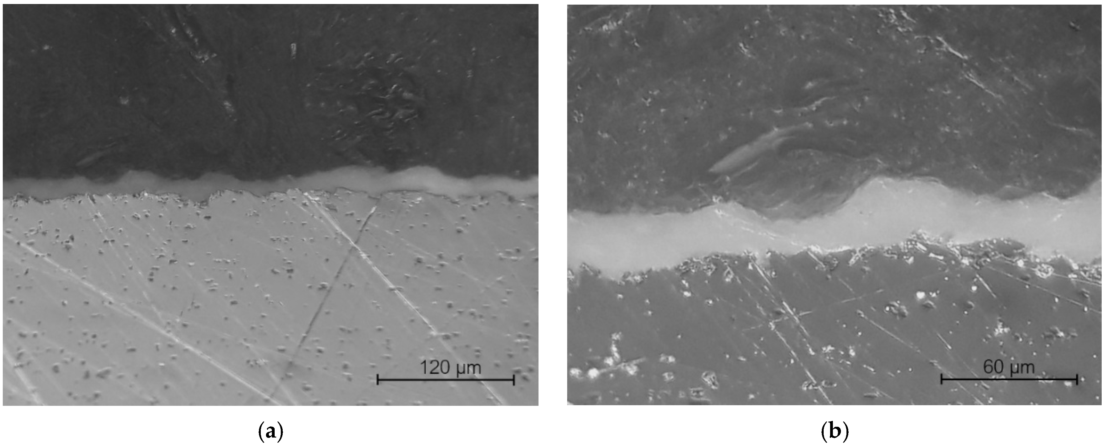
Optical micrographs (
Figure 6) taken before the exposure to the air jet illustrate that, for the coating method used, the luminophore has a uniform distribution in the binder, which certifies a good mixture, and a suitable viscosity for the deposition method. The coating is relatively uniform. The thickness of the active layer was measured to be approximately 15 µm, which represents 10 passes of the spray gun over the support. The temporal response characteristics of PSP are primarily governed by the thickness of the paint formulation and the diffusion coefficient of the binder material. In the future, an increase of at least 50% in the thickness of the paint layer, as well as the amount of PtOEP, is necessary in order to obtain a better result. This does not significantly affect the response time of the developed PSP. The composite layers are poorly highlighted, but their adhesion to the substrate and between layers is good, without cracks or pores in the coating. The particles and the polymer are homogeneously distributed in the film.
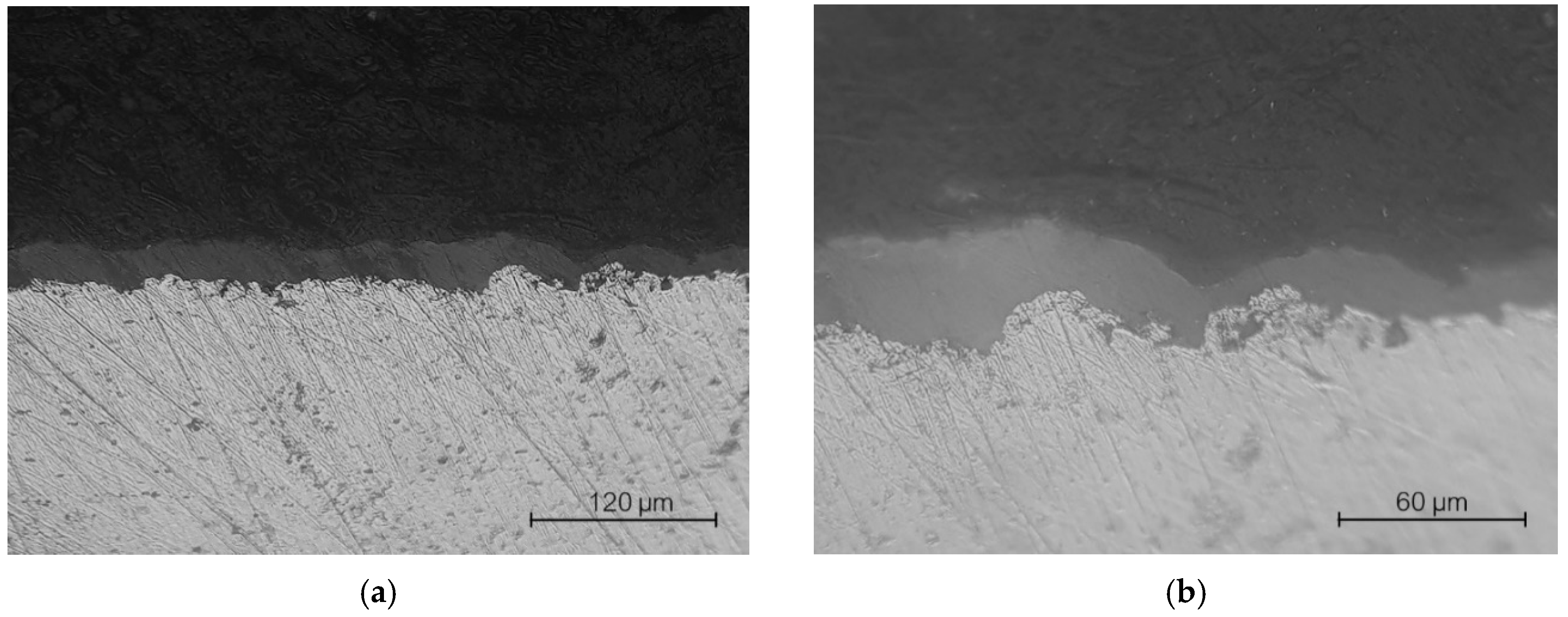
After exposure to the air jet, optical micrographs (
Figure 7) show that the deposited layers are slightly fractionated with a higher roughness and detachments from the upper layer are highlighted. Moreover, a porosity increase can be observed on the surface of the specimen, possibly also due to exposure to UV light.
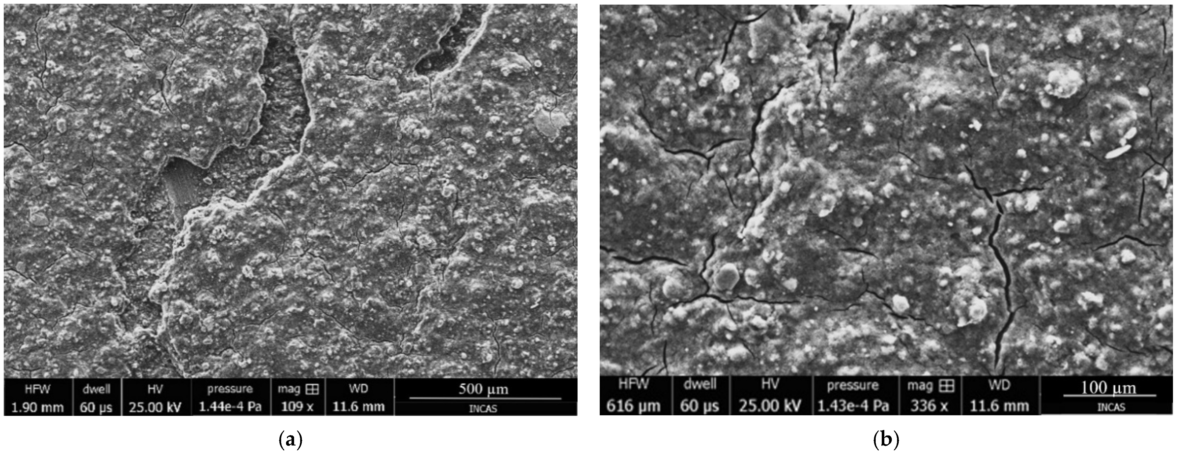
The SEM analysis was performed on the specimens obtained before (
Figure 8 and
Figure 9) and after (
Figure 10) being tested in UV light. The images shown are for corundum blasted models. Although it is not highlighted very well in the images showing the sample cross section (
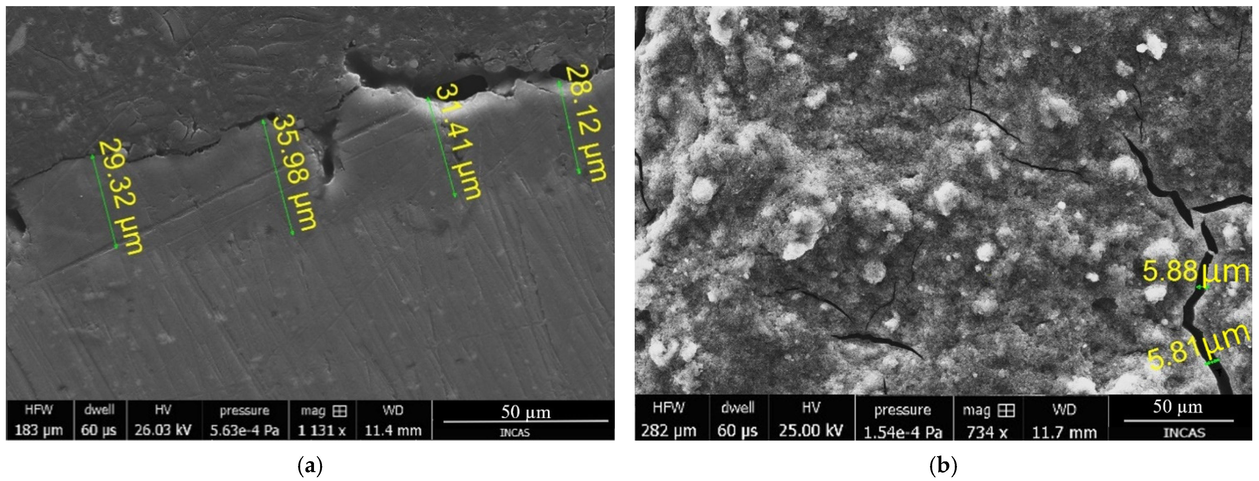
Figure 9), the specimens presented are with two layers of paint, the screen layer and the respective active layer.
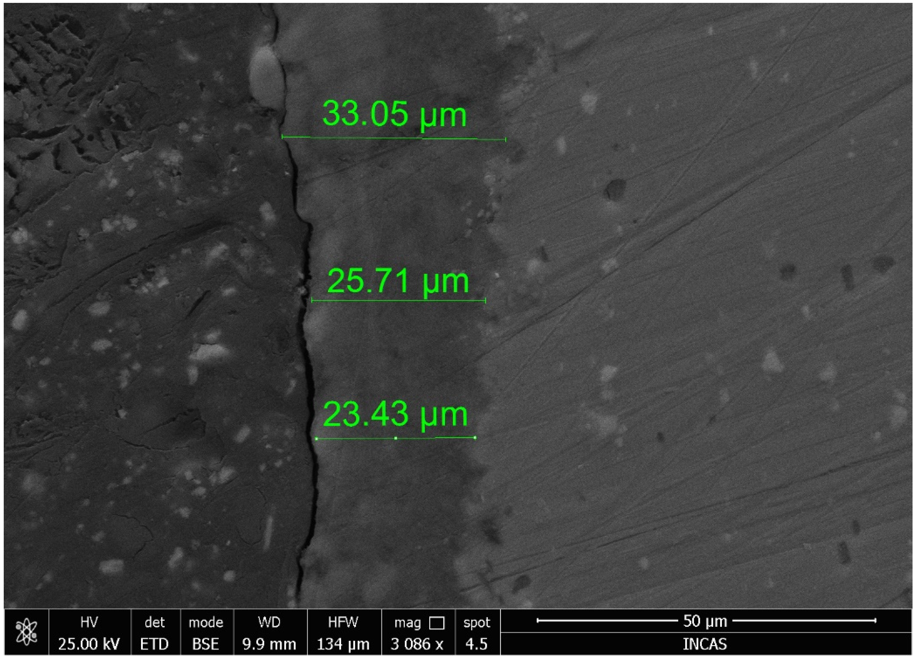
The samples show uneven thickness of the layers, but, as we expected, they have a porous architecture. This highlights the existence of ceramic particles in the layer that have a uniform distribution. These compounds generate the formation of the porous microstructure, which is closely related to the number of compounds in the system. In the first image, you can see a network of microcracks, with continuous lines. The thickness of the layer on the length analyzed and presented in
Figure 9a is uniform and varies between 28 and 35 µm. There is good adhesion of the screen layer on the surface of the substrate, as well as good adhesion between the two layers of paint. Locally, the specimen has cracks with an approximate depth of 15 µm (
Figure 9b). SEM images indicate that the aggressive sandblasting of the substrate ensured a proper activation of the surface for paint adhesion.
The SEM image (
Figure 10) of the samples tested in UV light does not indicate major changes in the coating. The coating maintains its integrity. Furthermore, on the analyzed area, there are no deep cracks in the layers.
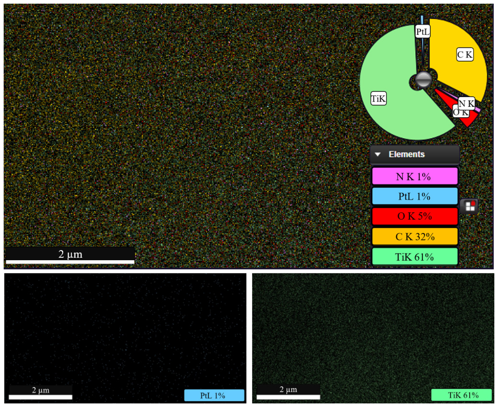
Figure 11 shows a uniform distribution of Ti and Pt particles over the entire analyzed area. From the quantitative analysis, a proportion of 1% Pt and 61% Ti is highlighted. The surface morphology is granulometric, displaying a porous structure.
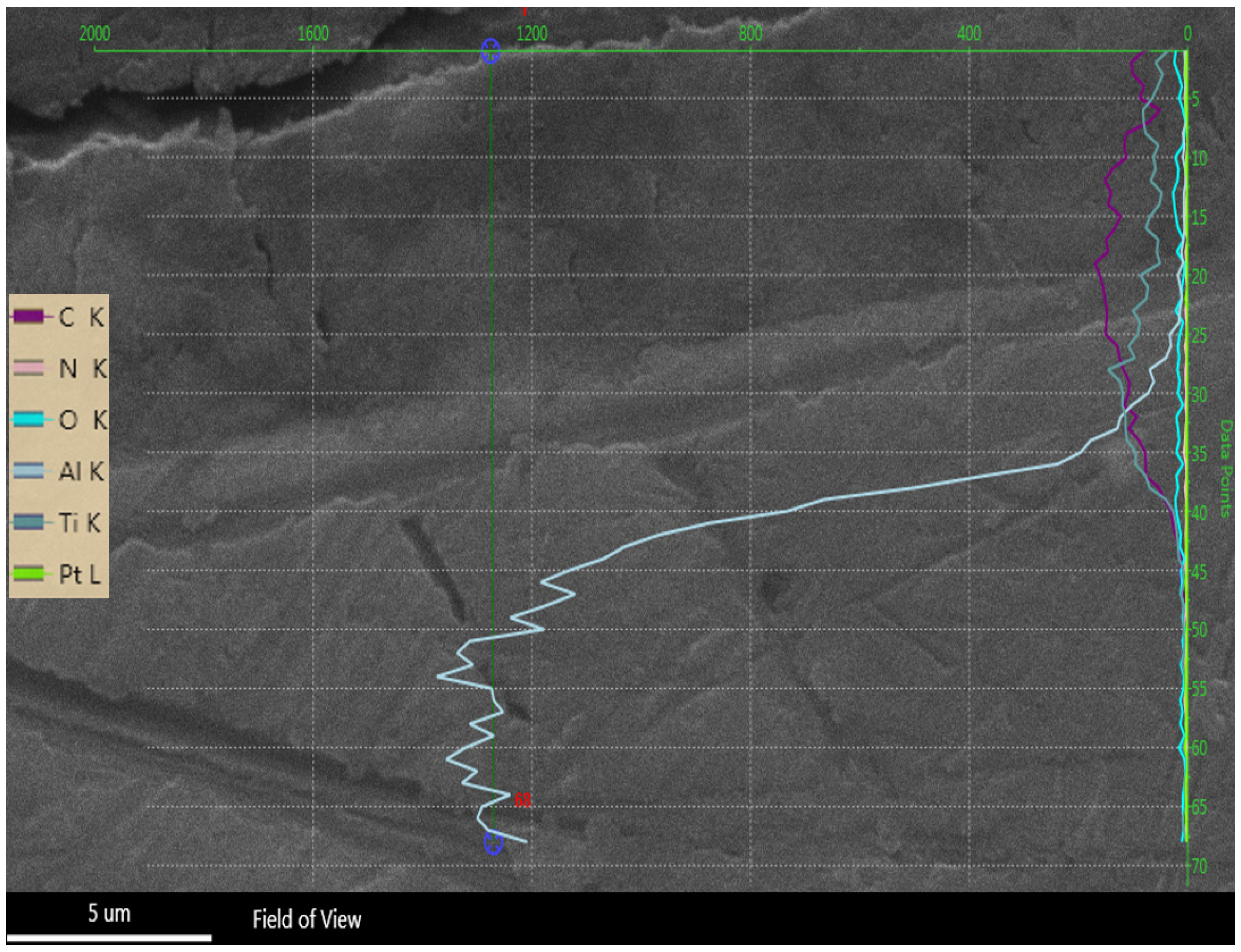
Figure 11 also shows a densified area with open intergranular pores. It can be concluded that the coating has an increased oxygen permeability, creating a favorable environment for the response of light agents in the active layer, and thus the model of pressure distribution can be translated as dispersion of particles in the deposited layers. In
Figure 12, the analysis was performed linearly, in order to observe the distribution of the component materials in both the deposited layers and in the substrate.
4. Conclusions
The paper presents the study of developing a pressure-sensitive paint and its adhesion to the support material, with the experimental discussion taking into consideration the adhesion evaluation as a function of the pretreatments to which the substrate was subjected. Following a pressure test by air flow exposure and morphostructural analysis, the best solution was obtained by dry sandblasting the surface with corundum in a compressed air jet. In the case of the other two methods, the deposited layers yielded after the scratch test or without any test. This indicates that the aggressive mechanical type treatment of the substrate surface involving corundum sandblasting is more suitable than the mild chemical treatment involving low concentration acetic acid.
Although previous experimental trials indicated that the most suitable ratio for the experimental conditions is 0.9 g/15 mL polystyrene/toluene and 1 g of TiO2, as it led to a high porosity uniform layer and good distribution of the luminescent particles in the binder, the response time of the developed paint was longer than expected. Following the preliminary studies presented in this paper, one can conclude that it is necessary to further investigate higher amounts of TiO2 in the formulated paint.
The SEM analysis showed, as we expected, a porous structure and highlighted a uniform distribution of ceramic particles in the coating.
The preliminary experimental data have shown that the developed paint is a viable solution in terms of providing values as close to reality, but it is necessary to continue research in the direction of its calibration in a pressure- and temperature-controlled chamber. The pressure will be monitored with a pressure sensor, and the temperature of the specimen will be monitored and adjusted with a thermocouple.
Author Contributions
Conceptualization, G.C.C. and S.I.; Resources, G.P.; Investigation, A.S. and C.E.P.; Methodology, S.I.; Software, G.C.C.; Validation, G.P., A.S. and C.E.P.; Writing—original draft, G.C.C.; Writing—review & editing, G.P., A.S. and C.E.P. All authors have read and agreed to the published version of the manuscript.
Funding
This paper was funded by Nucleu Program “Cercetări avansate pentru creșterea competitivității și capacității de concepție, analiză și expertiză specifică în domeniul aerospațial-AEROEXPERT 2019–2022”, Cod PN 19 01.
Institutional Review Board Statement
Not applicable.
Informed Consent Statement
Not applicable.
Data Availability Statement
Data are contained within the article.
Acknowledgments
This work is supported by the project ANTREPRENORDOC, in the framework of Human Resources Development Operational Programme 2014–2020, financed from the European Social Fund under the contract number 36355/23.05.2019 HRD OP/380/6/13–SMIS Code: 123847.
Conflicts of Interest
The authors declare no conflict of interest.
References
- Sakaue, H.; Hayashi, T.; Ishikawa, H. Luminophore application study of polymer-ceramic pressure-sensitive paint. Sensors 2013, 13, 7053–7064. [Google Scholar] [CrossRef] [PubMed] [Green Version]
- Scroggin, A.M.; Slamovich, E.B.; Crafton, J.W.; Lachendro, N.; Sullivan, J.P. Porous polymer/ceramic composites for luminescence-based temperature and pressure measurement. MRS Online Proc. Libr. 1999, 560, 347–352. [Google Scholar] [CrossRef]
- Gregory, J.W.; Asai, K.; Kameda, M.; Liu, T.; Sullivan, J.P. A review of pressure-sensitive paint for high-speed and unsteady aerodynamics. Proc. Inst. Mech. Eng. Part G J. Aerosp. Eng. 2008, 222, 249–290. [Google Scholar] [CrossRef]
- Fischer, L. New Materials for Temperature and Pressure Sensitive Fluorescent Paints. Ph.D. Thesis, Universität Regensburg, Regensburg, Germany, 2012. [Google Scholar]
- Bell, J.H.; Schairer, E.T.; Hand, L.A.; Mehta, R.D. Surface pressure measurements using luminescent coatings. Annu. Rev. Fluid Mech. 2001, 33, 155–206. [Google Scholar] [CrossRef]
- Torgeson, S.D.; Liu, T.; Sullivan, J.P. Use of pressure sensitive paints in low-speed flows, AIAA-96-2184. In Proceedings of the 19th AIAA Advanced Measurement and Ground Testing Technology Conference, New Orleans, LA, USA, 17–20 June 1996. [Google Scholar]
- McLachlan, B.G.; Bell, J.H. Pressure sensitive paint in aerodynamic testing. Exp. Therm. Fluid Sci. 1995, 10, 470–485. [Google Scholar] [CrossRef]
- ASTM D3359. Standard Test Methods for Rating Adhesion by Tape Test; ASTM International: West Conshohocken, PA, USA, 2017. [Google Scholar]
| Publisher’s Note: MDPI stays neutral with regard to jurisdictional claims in published maps and institutional affiliations. |
© 2021 by the authors. Licensee MDPI, Basel, Switzerland. This article is an open access article distributed under the terms and conditions of the Creative Commons Attribution (CC BY) license (https://creativecommons.org/licenses/by/4.0/).


