Article

Numerical Simulation and Parameter Analysis of Electromagnetic Riveting Process for Ti-6Al-4V Titanium Rivet

State Key Laboratory of Advanced Design and Manufacturing for Vehicle Body, Hunan University, Changsha 410082, China
*
Author to whom correspondence should be addressed.
Coatings 2021, 11(8), 878; https://doi.org/10.3390/coatings11080878
Submission received: 18 June 2021 / Revised: 8 July 2021 / Accepted: 20 July 2021 / Published: 22 July 2021

Abstract

:
Electromagnetic riveting process (EMR) is a high-speed impact connection technology with the advantages of fast loading speed, large impact force and stable rivet deformation. In this work, the axisymmetric sequential and loose electromagnetic-structural coupling simulation models were conducted to perform the electromagnetic riveting process of a Ti-6Al-4V titanium rivet, and the parameter analysis of the riveting setup was performed based on the sequential coupled simulation results. In addition, the single-objective optimization problem of punch displacement was conducted using the Hooke–Jeeves algorithm. Based on the adaptive remeshing technology adopted in air meshes, the deformation calculated in the structural field was well transferred to the electromagnetic field in the sequential coupled model. Thus, the sequential coupling simulation results presented higher accuracy on the punch speed and rivet deformation than the loose coupling numerical model. The maximum relative difference of electromagnetic force (EMF) on driver plate and radial displacement in the rivet shaft was 34.86% and 13.43%, respectively. The parameter analysis results showed that the outer diameter and the height of the driver plate had a significant first-order effect on the response of displacement, while the platform height, transition zone height, angle, and transition zone width of the amplifier presented a strong interaction effect. Using the obtained results on the optimal structural parameters, the punch speed was effectively improved from 6.13 to 8.12 m/s with a 32.46% increase. Furthermore, the displacement of the punch increasing from 3.38 to 3.81 mm would lead to an 80.55% increase in the maximum radial displacement of the rivet shaft. This indicated that the deformation of the rivet was efficiently improved by using the optimal rivet model.

1. Introduction

Due to the increasing demand for lightweight materials, such as aluminum alloy, titanium alloy, carbon fiber reinforced polymer (CFRP) in automotive fields, the traditional joining technologies face huge challenges in achieving excellent connection quality within qualified fatigue performance and service life. EMR is a high-speed impact connection technology with the advantages of fast loading speed, large impact force and stable rivet deformation [1]. Consequently, the EMR could effectively solve the technical bottlenecks such as the easy extrusion damage of the composite materials and the insufficient pneumatic riveting loading force of the titanium alloy rivets during the riveting process in the automobile and aerospace fields [2,3,4]. The electromagnetic riveted joint could achieve higher mechanical performance, such as the fatigue properties and pull-out strength than the traditional riveted joints because of the homogeneous expansion of the rivet [5,6,7].
In the EMR process, the mutually exclusive EMF was an instantaneous, homogeneous, and stable impact force acting on the rivet [1,8]. The EMR device mainly consisted of two parts: discharge equipment (electromagnetic force setup) and riveting setup [9]. The EMF setup provided the riveting energy based on the resistor-inductor-capacitor (RLC) attenuating oscillating circuit, which was composed of capacitor banks, a resistor, an inductor, and coils [10]. In detail, the discharge equipment first released the high-frequency current through the coil and generated the motional current in the driver plate. Consequently, a high-intensity repulsive force was produced between the coil and the driver plate and propagated in the form of waves inside the amplifier. After multiple transmission, reflection, and superposition, the plastic deformation on the rivet shaft caused by the impact forces led to the riveted connection on target sheets, eventually.
According to the principle above, EMR has advantages in joining dissimilar materials with a stable forming process and uniform deformation. Thus, many researchers paid attention to the mechanical properties and failure behaviors of electromagnetic riveted joints [6,11]. For instance, Jiang et al. [9] investigated the mechanical behaviors (static tensile and fatigue properties) of Al-CFRP electromagnetically riveted lap joints. The results showed that the rivet squeezing effect under static shear loading caused the bending of the Al sheet and the damage of the CFRP sheet. Moreover, Jiang et al. [12] put further efforts into the mechanical properties of Al/CFRP EMR joints and found that the locking modes and discharge energy had obvious effects on connection performance. In addition, Jiang et al. [13] achieved Al/steel self-piecing riveted-adhesive hybrid joints by an electromagnetic riveting process, and the mechanical tests showed better reliability than the separated connection methods.
In order to systematically investigate the parameters (current density, stress, strain, etc.), a finite element analysis was widely adopted to explore the deformation process during EMR comprehensively and in detail [7,14,15]. Reinhall et al. [16] found that the excessive radial flow of materials caused large shear levels and induced microcracks through the FE model of EMR. Repetto et al. [17] established a finite element model of EMR considering the dynamic and thermal effects to analyze the rivet plastic deformation and thermal distribution. However, the EMR process was an interaction process among the electromagnetic field, structural field, and temperature field [18]. The electromagnetic field significantly affected the accuracy of simulation. Recently, the loose coupling method and the sequential coupling method have been the common finite element methods for solving electromagnetic-structural coupling problems [19,20,21]. Many researchers investigated the divergence between loose coupling and sequential coupling numerical simulation method of the electromagnetic forming process. Bartels et al. [22] adopted two different simulation methods of the electromagnetic metal forming process. The simulation results showed that the deviation between two methods gradually increased with time and led to the overestimation of the loose coupling numerical model. Yu et al. [23] found that the simulation accuracy of sequential coupling simulation for electromagnetic tube compression was highly improved by considering the effect of tube deformation on the electromagnetic geometry. However, the studies of differences between the two algorithms in the EMR process were limited.
Based on the quantitative information obtained in simulation results, the finite element model can be used as the basis for determining the technical parameters in the EMR process. Cui et al. [24] studied the structural effect of the rivet die on the formation mechanism of the adiabatic shear bands (ASBs) and obtained the optimal riveting die. The comprehensive research conducted on the coil showed the trapezoid cross section coil generated the largest riveting force compared to rectangular, pentagonal, and circular types [25]. Qin et al. [26] presented a parameter optimization procedure to design the rivet die for better mechanical performance of the EMR joints. Note that the abovementioned parameter studies were aimed at the subjects of the coil and the rivet die. The other two major parts of the EMR setup, namely the driver plate and the amplifier, have not been explored yet. Meanwhile, the driver plate undertook the whole EMF, and the amplifier reflected and superimposed the stress wave into the rivet. Thus, it was of great significance to study the parameter effects of the structural parameters within the driver plate and amplifier.
In this paper, the axisymmetric sequential and loose electromagnetic-structural coupling simulation models were conducted to perform the electromagnetic riveting process of a Ti-6Al-4V titanium rivet, and a parameter analysis of the riveting setup was performed based on the sequential coupled simulation results. Firstly, loose coupled and sequential coupled EMR simulation models were established in the 2D axisymmetric form separately to simulate the EMR process of aluminum alloy sheets with a titanium alloy rivet by using multi-physic software ANSYS. Then, the obtained results of EMF, current density on the driver plate, the rivet velocity of the punch, and the deformation form of the rivet were compared to assess the divergence of different types of numerical models. Next, a parameter analysis of the riveting setup (driver plate and amplifier) was performed based on the sequential coupled simulation results. Finally, the single-objective optimization problem of the punch displacement was conducted using the Hooke–Jeeves algorithm.

2. Simulations and Experiments

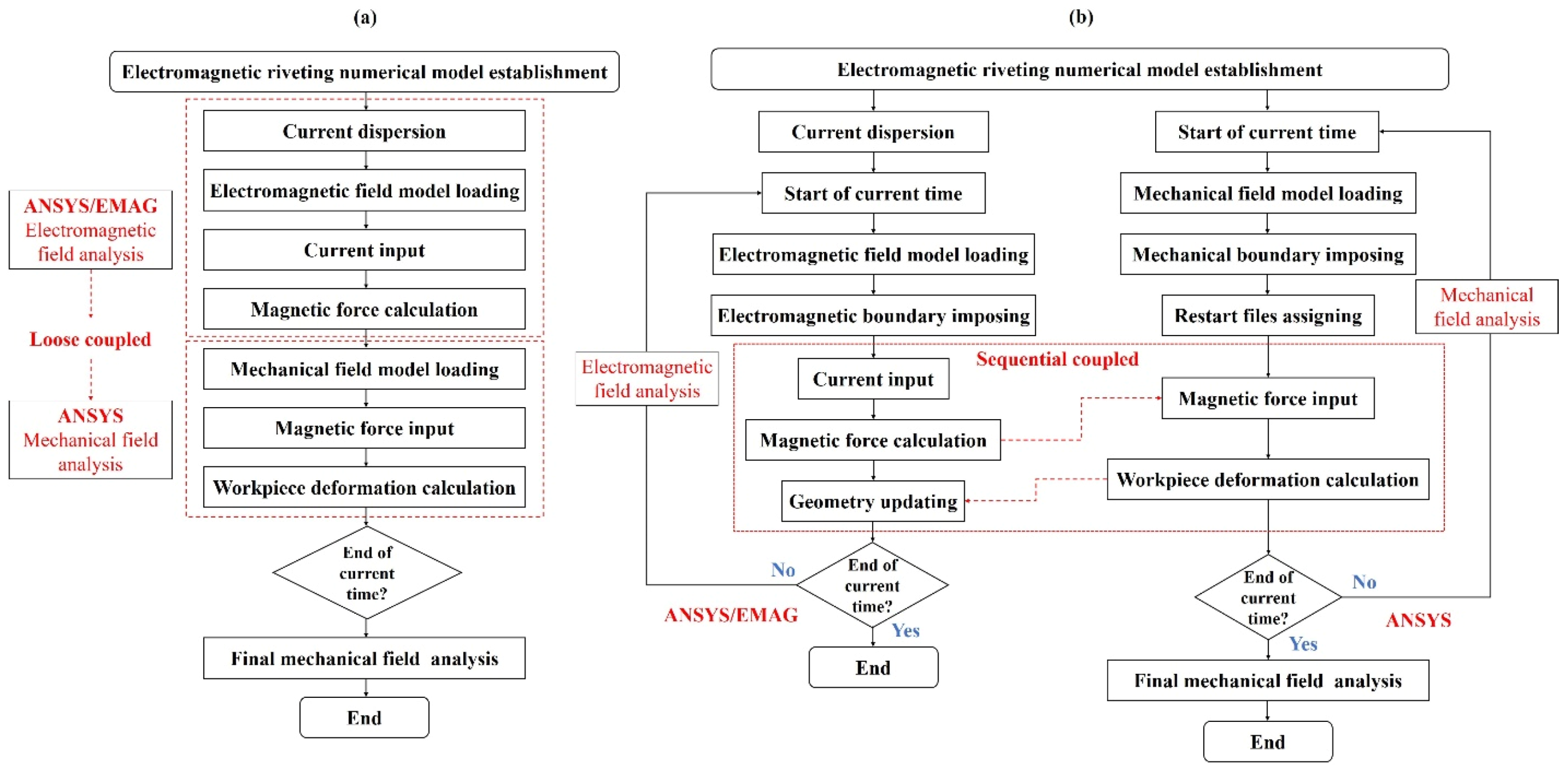
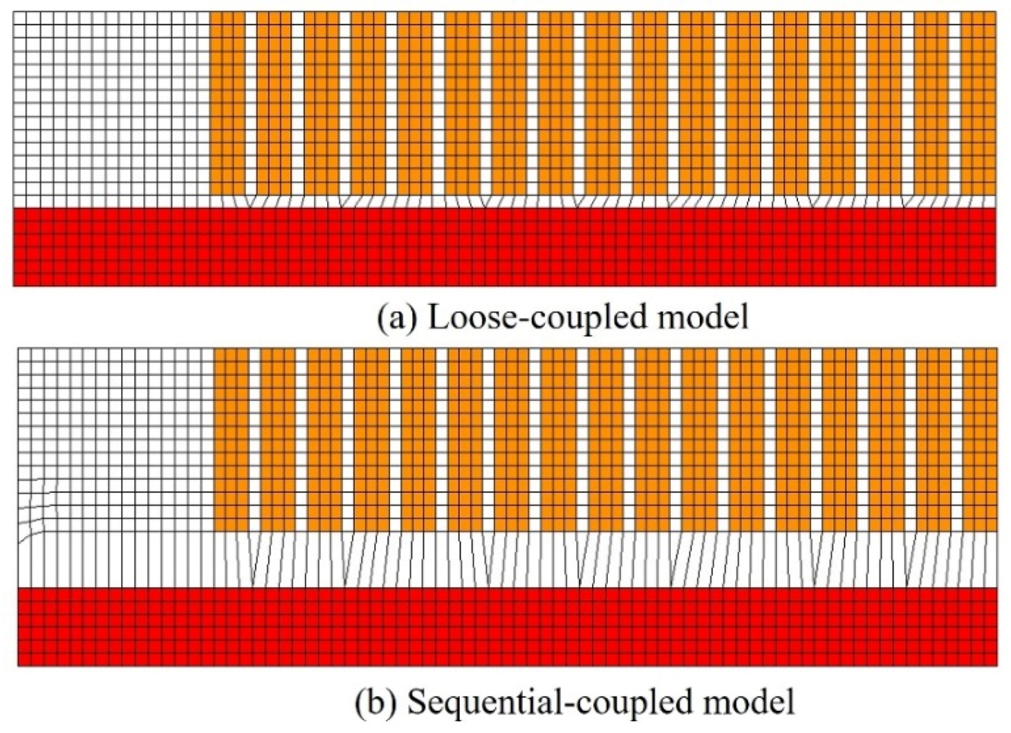
2.1. Principle of Loose-Coupled and Sequential-Coupled Simulation Method

The flow chart of the loose-coupled and sequential-coupled simulation models for EMR is illustrated in Figure 1. The electromagnetic field analysis and structural field analysis were solved in ANSYS/EMAG and ANSYS, respectively. It can be easily seen that the loose coupling model treated the electromagnetic field and structural field as two independent issues, while the electromagnetic analysis and the structural analysis were iteratively performed in the sequential coupling model. The calculated deformation results were updated to the electromagnetic field based on the adaptive remeshing technology used in air meshes.

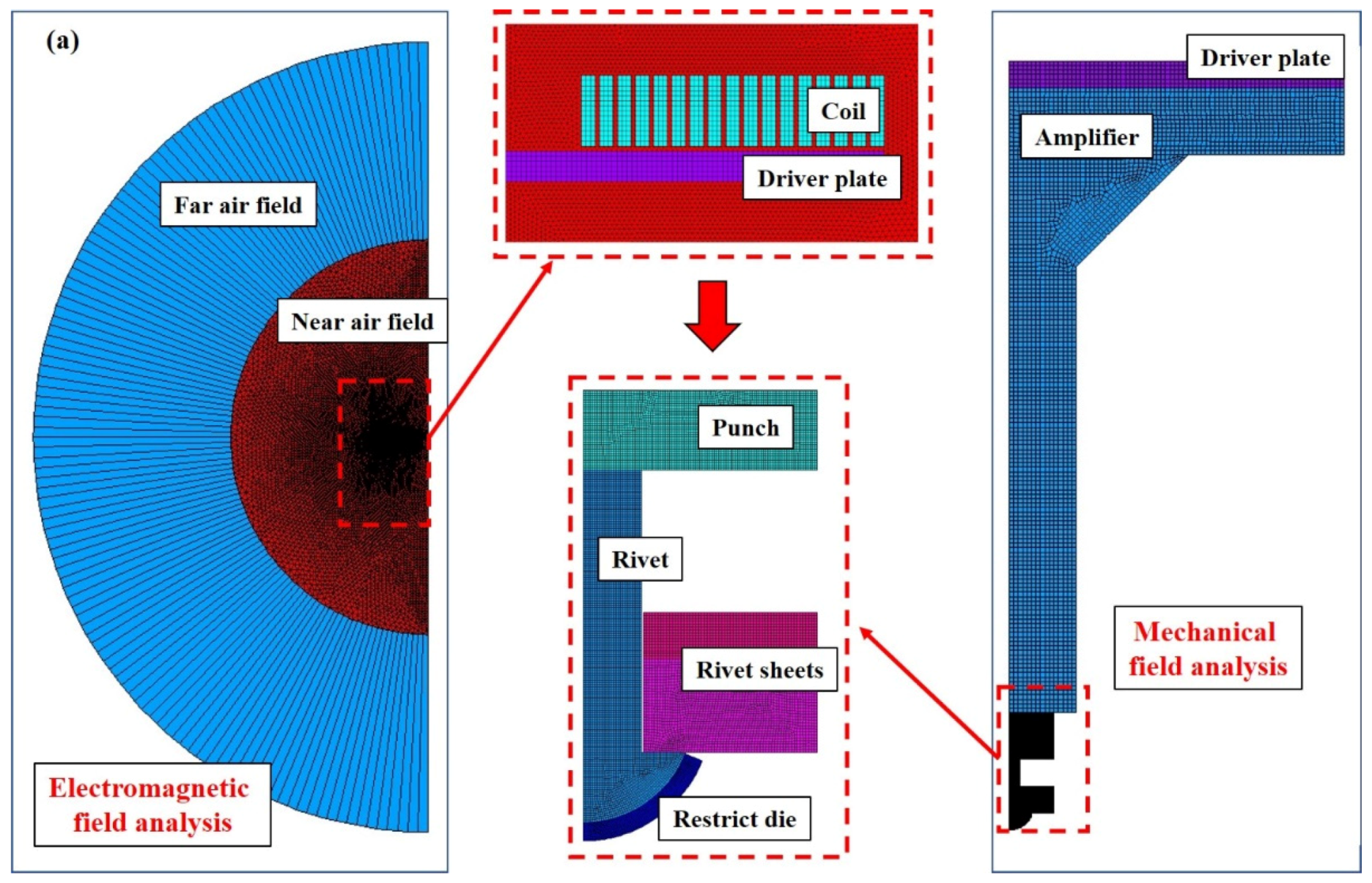
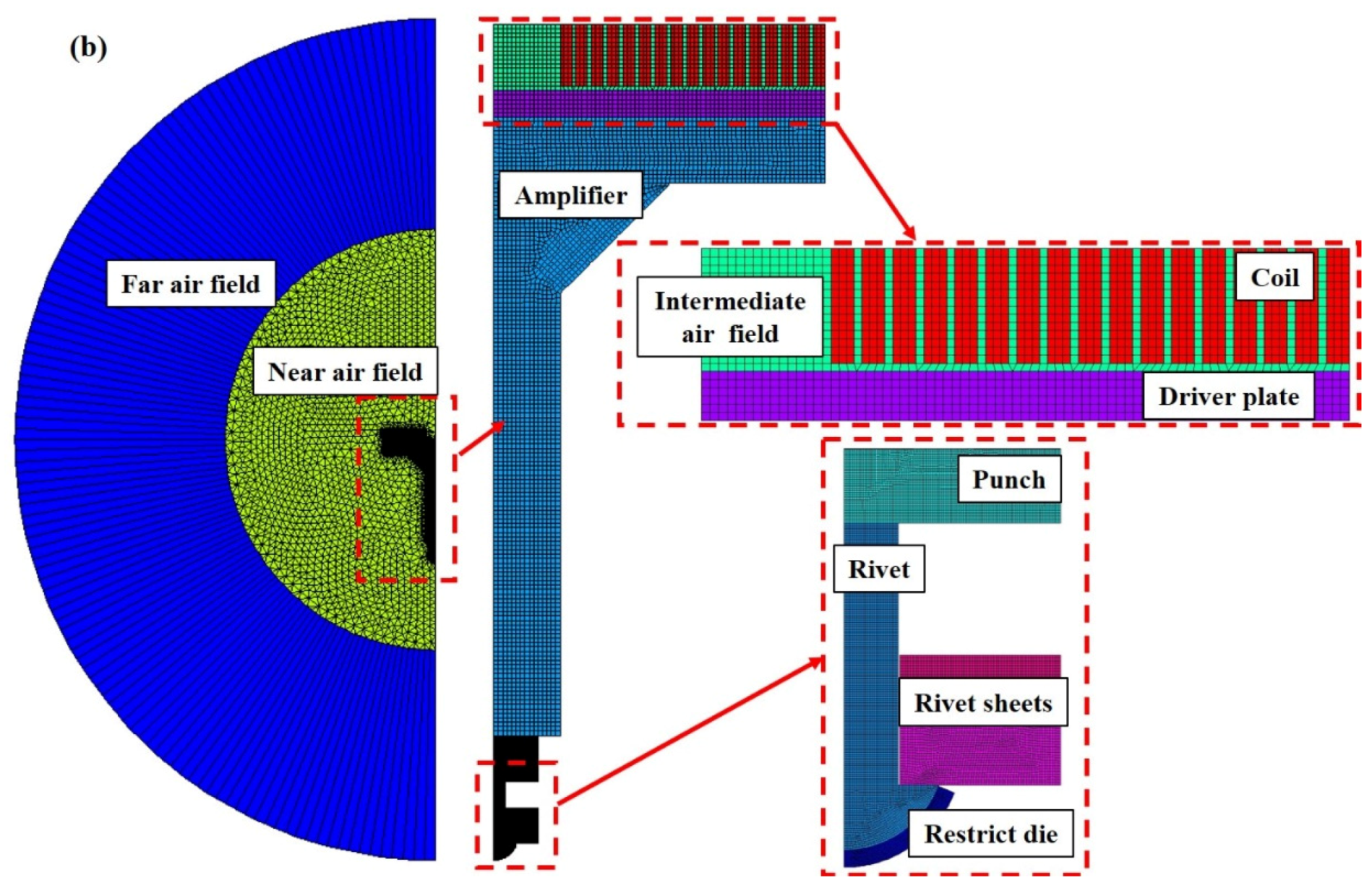
2.2. Establishing of Finite Element Model

Figure 2a shows the finite element model (FEM) used for the analysis of the 2D axisymmetric EMR model using the loose-coupled method. The electromagnetic field model consisted of four components (far air field, near air field, coil, and driver plate). For the mesh of the far air field, element type INFIN110 was adopted on account of the dissipation air. Other components were all built with element PLANE13. The boundary of the far air field and near air field was 4 times and 8 times as large as the radius of the driver plate, respectively. The magnetic flux parallel and infinity boundary conditions were set up to the symmetry axis and the boundary of the far air field separately based on the boundary conditions. During the structural field simulation, a penalty contact function with the friction coefficient value of 0.2 was adopted to simulate the contact behavior. In order to balance the calculation accuracy and calculation efficiency, the mesh sensitivity study have conducted on the deformable bodies before the further analysis of electromagnetic and structural field results. Upon the mesh sensitivity results, the mesh size of the rivet, riveted sheets, punch, and restrict die were set to 0.1 mm.
Compared with the loose-coupling algorithm, the electromagnetic model and the structural model were coupled in the sequential numerical model. The EMF calculated in the electromagnetic field was used as a boundary condition to the structural field in implicit dynamic finite element code. Meanwhile, after the geometry update of the driver plate deformation, the intermediate air field was meshed with the adaptive remeshing method. As in the axial symmetrical sequential coupled numerical model shown in Figure 2b, the intermediate air field was meshed through the mapped meshing method with 13 plane elements. In the structural field analysis, the coil and all of the air fields were set to “null” element types, and the element type of the driver plate, amplifier, punch, rivet, riveted sheets, and the restrict die were converted into 182 plane elements. In the sequential coupled models, the same boundary conditions and the material properties of the loose coupled simulation model were used. The elements used in modeling the electromagnetic field are shown in Table 1.
The discharge current of the EMR system is presented in Figure 3. As shown in Figure 3b, the discharge current was divided into 89 uniformly-spaced timesteps and loaded into the section of the coil. In the electromagnetic field, the current density on the section of coil was calculated by the input of the discharge current. Based on the working principle of the EMR system, the discharge current of the circuit could be calculated by Equation (1).
i ( t ) = U c ω L e β t s i n ω t = I m s i n ω t
β = R 2 L
ω = 1 L C R 2 4 L 2
where i(t) is the discharge current (kA), Uc is the discharge voltage (kV), Im is the maximum value of the discharge current (kA), ω is the oscillatory frequency of the RLC circuit (rad⋅s−1), β is the current attenuation coefficient, C is the discharge capacitance and L is the system inductance (29). Moreover, the electrical parameters of the discharge system are shown in Table 2.
The structural field model consisted of a driver plate, amplifier, punch, rivet, riveted sheets, and restrict die. All the components were meshed in 185 plane elements. In the implicit finite element code, the transient dynamic equilibrium equation is as follows, and the Newmark time integration method in the ANSYS was adopted to solve it.
M u ¨ + D u   ˙ + K u = F
where M is the structural mass matrix (kg), D is the structural damping matrix (kg/s), K is the stiffness matrix (kg/s2) and F is the load vector (N).
The AA5052 aluminum alloy sheet of 2 mm and the AA6082 aluminum alloy sheet of 4 mm were jointed with Φ5 × 12 mm Ti-6Al-4V titanium rivets by the EMR experiments. Based on the general riveting technical requirement, the diameter of the holes in the sheet was prefabricated to 5.15 mm. Due to the instantaneous large plastic deformation of the rivet, the Cowper–Symonds model (as shown in Equation (5)) was adopted to characterize the constitutive relationship of the materials at high strain rates [27].
σ = σ y [ 1 + ( έ p ) m ]
where σ y is the quasi-static flow stress, έ is the plastic strain rate (s−1), p and m are Cowper–Symonds multiplier (p = 6500 s−1 and m = 0.25 for aluminum alloy materials, respectively [14]).
The coefficient in Equation (5) was obtained by a quasi-static tensile test carried out by using the universal Instron 5569 electronic testing machine under a stretching velocity of 2 mm/min. Figure 4 demonstrates the quasi-static tensile stress-strain curves of AA5052 and AA6082 aluminum alloy, while the plastic deformation segment was fitted with the Cowper–Symonds function. The detailed material properties used in the numerical model obtained from the fitted results are exhibited in Table 3. In addition, the Cowper–Symonds parameters of the Ti-6Al-4V titanium rivet used in this study were cited from Chen’s experimental procedure [28].

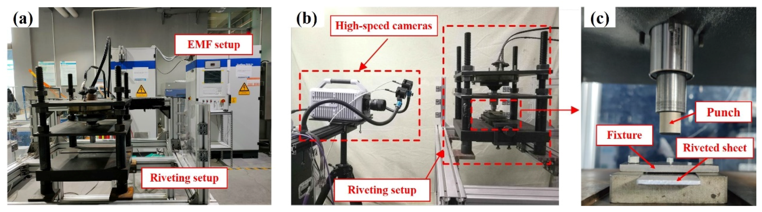
2.3. Trial-Manufacture of Rivet

In order to verify the accuracy of the above finite element model and the feasibility of the EMR process, the AA5052 aluminum alloy sheet of 2 mm and the AA6082 aluminum alloy sheet of 4 mm were jointed with Φ5 × 12 mm Ti-6Al-4V titanium rivets. Figure 5 shows the diagram of the EMR equipment and impact velocity measuring equipment. As shown in Figure 5b, the punch speed was shot by a high-speed camera with a digital image correlation (DIC) 3D full-field strain analysis system to compare the actual and the numerical punch speed.

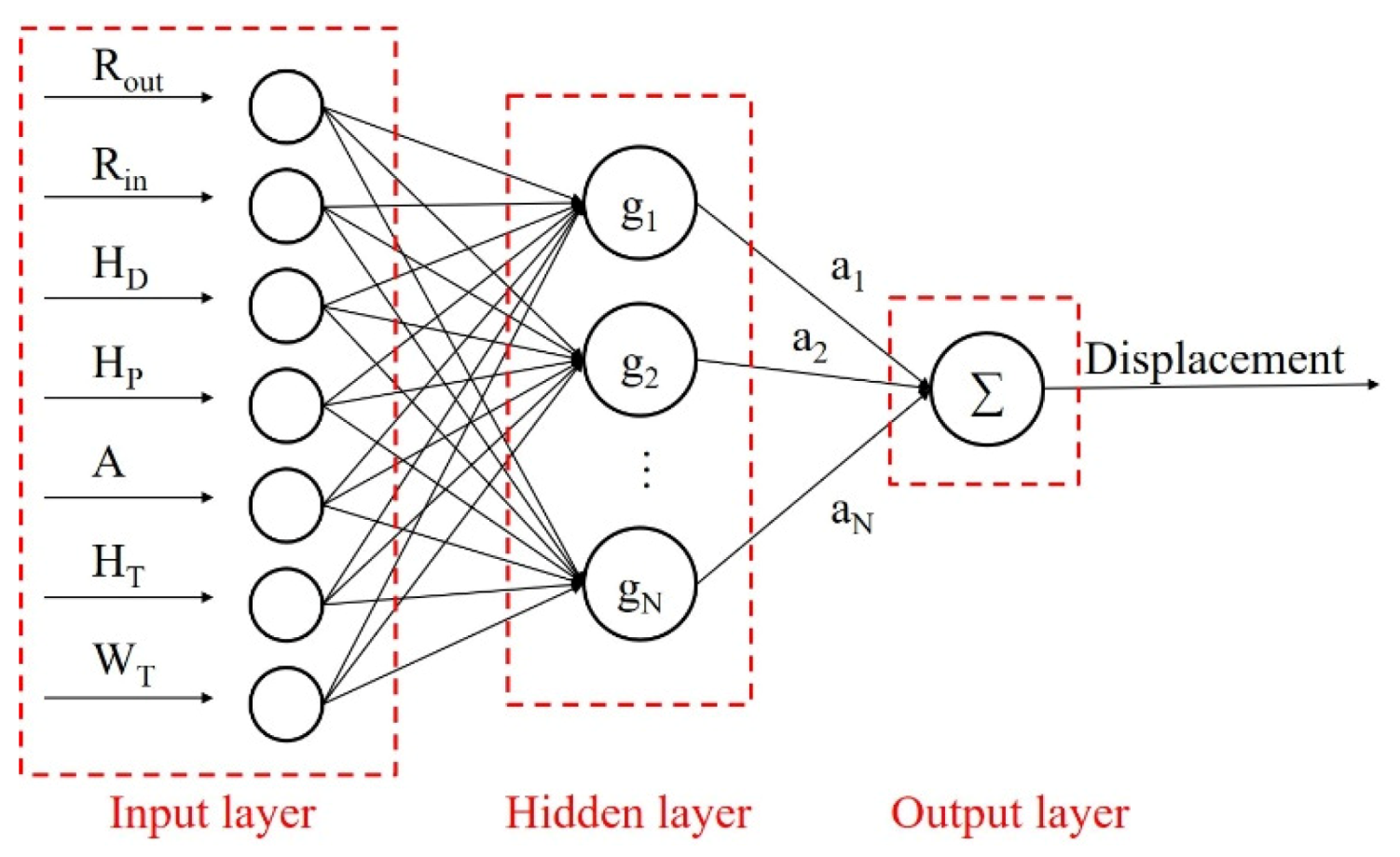
2.4. Radial Basis Function Approximation Model

RBF is a type of neural network employing an input layer, a hidden layer of radial units and an output layer of linear units. The RBF approximation algorithm are characterized by fast training efficiency and compact networks, which are useful in approximating a wide range of nonlinear spaces [29,30]. The RBF interpolation function is calculated according to:
y i = j = 1 N a j g j ( x )
where x 1 , , x N Ω R n present the set of input vectors [31], gj(x) is the basic function of the nth node in the hidden layer, aj are weights associated with the nth node in the hidden layer, N denotes the number of neurons in the hidden layer. The process function gj(x) is in the following form
g j ( x ) g ( || x x j || ) R ,   j = 1 , , N ,
where ||x−xj|| is the Euclidean distance, xj is the RBF center in the input vector. The Euclidean distances for each neuron in the hidden layer are calculated between its associate center and the input to the network.

3. Results and Discussions

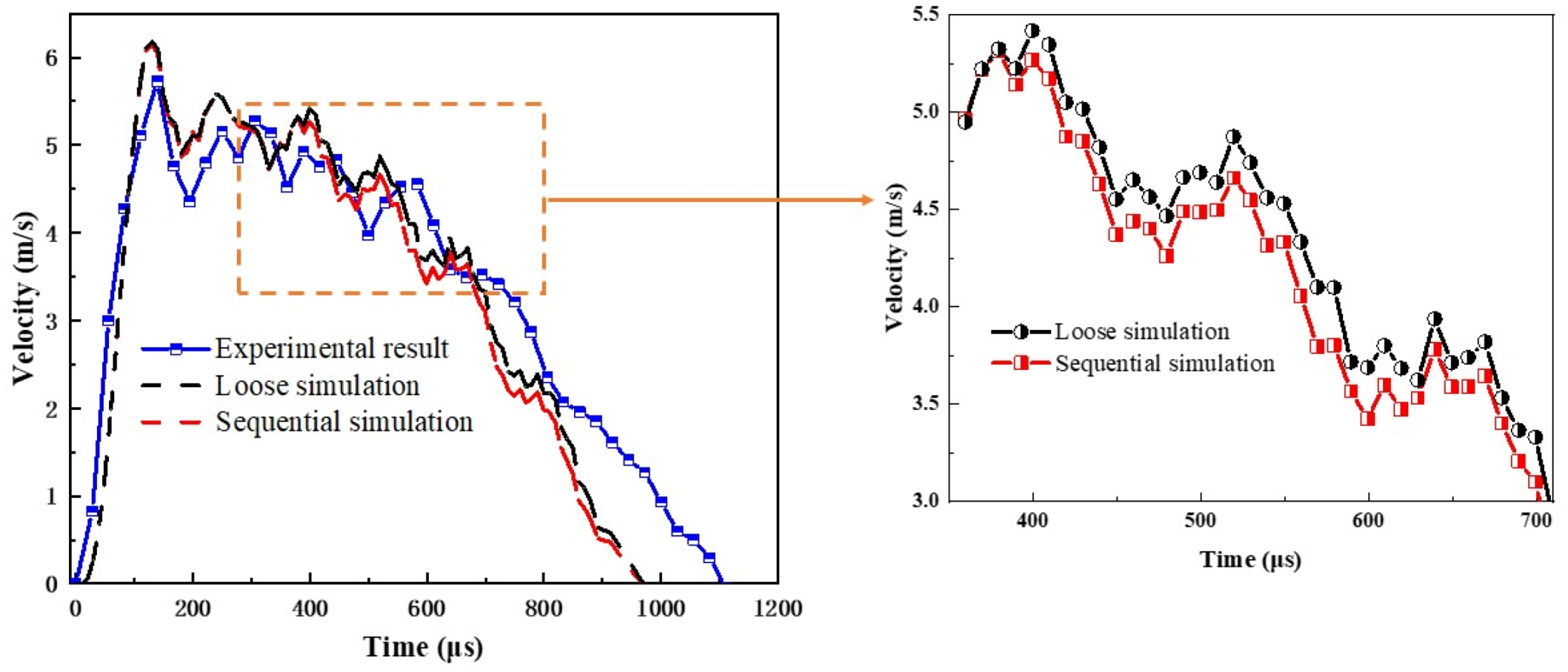
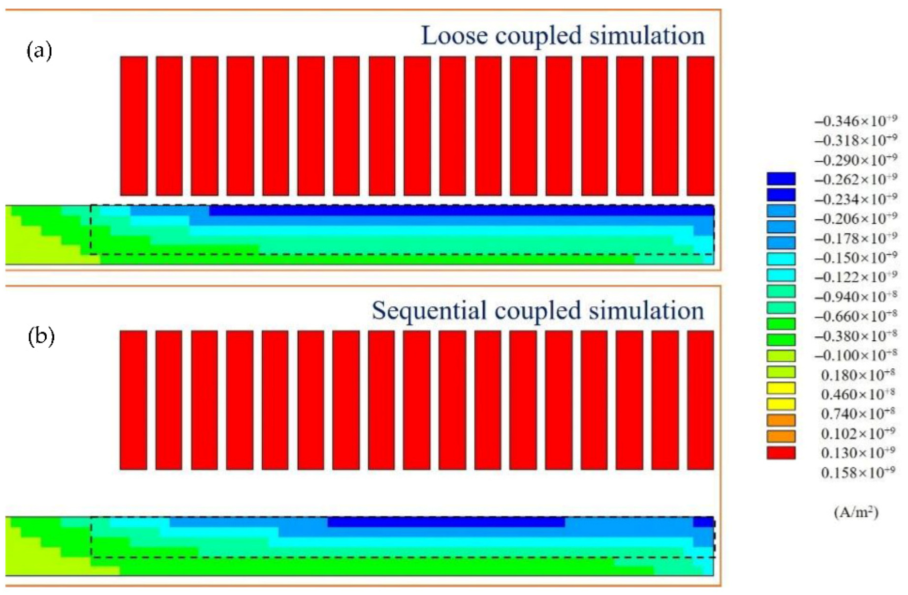
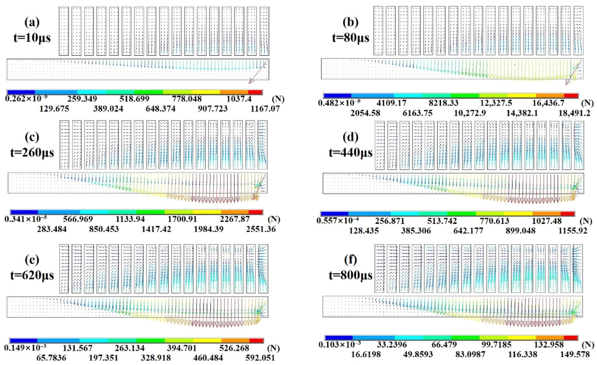
3.1. Comparisons between Loose-Coupled and Sequential-Coupled Numerical Models

Figure 6 compared the updated electromagnetic field model at 890 μs based on the structural deformation result using two algorithms. With the changing driver plate displacement, the intermediate air field deformed regularly without a distortion unit. Consequently, the calculation results could be transferred well from the structural field model to the electromagnetic field model. The magnetic-structural coupling problem was solved in the 2D sequential-coupled model. Based on the results in Figure 6, a marked change performed in the current density contribution results at the time of 800 μs. Figure 7 shows the distributions of current density on the driver plate and the coil at 800 μs using the loose and sequential-coupled methods. In the discharge process, the current direction in the coil was opposite to the induced eddy current direction in the driver plate. Therefore, the opposite magnetic field direction generated the repulsive force between the coil and driver plate. In addition, the induced eddy currents were unevenly distributed along the radius and thickness direction in the driver plate. In the loose-coupled model, a more effective eddy current region was induced in the driver plate within the skin effect due to the omission of the deformation.
Figure 8 and Figure 9 show the simulated vector results of the EMF distribution in the driver plate in the loose and sequential coupling models. The contribution tendencies of the EMF on the driver plate by two algorithms were similar at different times. Due to the skin effect, the magnetic field strength of the internal element was zero. The EMF was only generated in the upper layer element in the center area of the driver plate. Furthermore, the EMF of the outer edge was not perpendicular to the plane of the driver plate because of the non-parallel magnetic induction lines. Moreover, the uneven EMF distribution along the radius of the drive plate was consistent with the current density distribution, since the EMF came from the repulsive interaction between the induced magnetic field and coil magnetic field. However, the peak Lorentz force was generated in the outer edge of the driver plate. This is because the EMF in the driver plate was affected by the current density as well as the point effect. As a consequence of the omission of the driver plate deformation, the loose-coupled model predicted a larger magnetic force than the sequential-coupled model.
In order to evaluate the electromagnetic field response between two simulation algorithms, Figure 10 shows the change of EMF at a measured point with time. The EMF obtained by the loose and sequential coupled method almost coincided with each other before 20 μs. The reason is that the displacement of the driver plate was limited at this time (within 1 × 10⁻³ mm). After 20 μs, the EMF response from the loose-coupled model was overestimated compared to the sequential numerical model. With the time increasing, the relative difference of electromagnetic force gradually rose and reached a maximum value of 34.86%. This indicated that the displacement of the workpiece had an unignorable influence on the electromagnetic force. The differences in the EMF responses were directly mapped to the corresponding current density response.
Under the condition that five current waves were considered, Figure 11 shows the changes of impact velocity of a punch in two simulation approaches. Unlike the EMF response, the impact velocity of the sequential coupled model differed at 300 μs with the loose coupled model. Since the EMF was calculated based on the origin position of driver plate, the punch velocity calculated by the loose coupled method was larger than the sequential simulation model. Consequently, the deformation of the rivet was overestimated compared to the experiment in the loose coupling numerical model, as shown in Figure 12.
In order to verify the accuracy of the rivet deformation, the riveted specimen was cut along the axis of the rivet shaft. Figure 12a,b shows the comparisons between the numerical simulation result and metallographic microstructure result inside the rivet using two algorithms. It was obviously seen that the rivet head had the same drum characteristics and the same zoned deformed structure on both sides. In addition, the severe deformation occurred in the center position of the rivet head both in the metallographic result and simulation result. As shown in Figure 12c, the comparison of radial displacement in the rivet shaft between the two methods was quantitatively analyzed through the relative difference. From the bottom side to the top side of the rivet shaft, the relative difference of the radial displacement significantly increased and reached a maximum value of 13.43%.

3.2. Parameter Optimization Strategies Based on Sequential-Coupled Simulation

3.2.1. Design Response and Variables

The structural parameters of the driver plate and the amplifier were determined with the consideration of manufacturability and the boundary condition of the coil (as shown in Figure 13). As a result, inner diameter (Rin), outer diameter (Rout), height of driver plate (HD), height of platform (HP), height of transition zone (HT), angle (A), and width of transition zone (WT) were selected as the input variables. The design domain dimensions of each parameter are presented in Table 4. In each sample, the shape contour was checked to guarantee the manufacturability of the amplifier.
Based on the above discussion, the sequential coupled simulation model was chosen for the subsequent parameter analysis. In the EMR process of flat die, the punch displacement significantly affected the interference of the rivet. In order to improve the energy utilization ratio of the riveting setup, the displacement of the punch was chosen as the main response.

3.2.2. Radial Basis Function Model Results

The optimal Latin hypercube sampling technique [32,33] was performed to generate the sampling points using the sequential-coupled numerical model for the advantages of normal distribution and the enhancement of the overall data fitness. By sampling the design space 500 times, a total of 349 valid sampling points were obtained. The network architecture of RBF prediction model is shown in Figure 14. For the EMR process, this network predicted the punch displacement and impact velocity for the given structural parameters of the driver plate and amplifier. The elliptical basis function with the Mahalanobis distance was adopted in this paper due to the ability to rank the input variables in the order of influence on the output variable. The Gaussian function was used in this work as the processing function. Within the 349 valid sampling points, 325 points were used as the training data to construct the RBF regression model and the remaining 24 points were used as the test data. The root mean square error of the RBF approximation model was 6.11%.
The punch displacement and impact velocity approximation model obtained from the RBF analysis are shown in Figure 15 and Figure 16. The effects of inner diameter and the driver plate height were examined with a constant outer diameter (Rout) of 75 mm in Figure 15a. Similarly, the constant inner diameter (Rin), driver plate height (HD), platform height (HP), transition zone height (HT), angle (A), and transition zone width (WT) were set as 10, 5.5, 10, 20 mm, and 45°, respectively. The RBF approximation results showed the punch displacement was highly affected by the structural parameters of the driver plate. As seen in Figure 15b,c, the punch displacement was affected linearly by the outer diameter. This indicated that only the linear terms and the interaction influence of the outer diameter was involved in the response. Furthermore, the displacement was also influenced by the second-order terms of driver plate height and the inner diameter, and the interaction between driver plate height and the inner diameter, which generated a curvature in the displacement response surface.
As shown in Figure 16, the displacement response surface included different interactions among the parameters of the amplifier. However, the effect of the second-order terms and the interaction function appeared to be much higher comparably, which could be explained considering the mass of the amplifier and the structure of the transition zone. Specifically, Figure 16a,c demonstrated that there were two optimal ranges for the angle of the transition zone with differently matched HT and WT. The first range was 0° to 20°, while the second range was 40° to 60°. Consequently, the optimal combinations of the structural parameters of the transition zone were multi-directional. On the other hand, the height of the transition zone was only involved in the interaction with WT. In addition, the height of the platform only interacted with the width of the transition zone. As shown in Figure 16b, with decreasing HP, the displacement of punch increased and therefore, the energy utilization ratio increased since the displacement of the punch would be strictly related to the volume of the amplifier.
A Pareto effect plot was commonly adopted to compare the relative magnitude and statistical significance of the main effect, square effect, and the interaction effect. The Pareto effects of all significant parameters in the driver plate and amplifier (beyond the reference line) are shown in Figure 17. It can be obviously seen that the outer diameter (Rout) and the height of the driver plate (HD) have a significant first-order effect on the response of displacement. This is because the outer diameter of the driver plate had an important effect on the EMF utilization, while the height significantly influenced the weight of the driver plate. In addition, the structural parameters of the amplifier had a strong interaction effect on the displacement response. This second-order and third-order interaction effect illustrated the curvilinear contour in Figure 16. The most remarkable interaction effect between the transition zone height (HT), angle (A), and transition zone width (WT) revealed the design of the transition zone could efficiently enhance the response of displacement. In addition, the platform height (HP) showed an unignorable first-order effect, which was consistent with the result in Figure 16b,d. This was because the structure of the driver plate had an important effect on the EMF utilization and further influenced the riveting process. Moreover, the structure of the amplifier dominated the force transmission path and most of the weight of the equipment, which was a multi-level synthesis of shape parameters.

3.2.3. Results of Parameter Optimization

The single-objective optimization problem of punch displacement was conducted using the Hooke–Jeeves algorithm. Manufacturability restrictions were considered to guarantee that the solution point was feasible for the machinability criterion. The optimal structural parameters of the driver plate and amplifier are presented in Table 5. Using the obtained results on the optimal structural parameters, Figure 18 shows the history of the y-velocity of the punch and the diagram of the driver plate and amplifier under EMR before and after optimization. It was found that the optimal design could effectively improve the velocity of the punch from 6.13 to 8.12 m/s with a 32.46% increase.
As shown in Figure 19, the EMF distribution on the driver plate differed greatly between the optimal and baseline design. For the baseline design, the EMF has a significant point effect on the outer edge of the driver plate. Meanwhile, there was little EMF on the inner edge. For the optimal design, the EMF smoothly transited in the end of the coil. The increase of the outer diameter of the driver plate increased the utilization of the EMF. Figure 20 demonstrates the comparison of equivalent strain in rivet and radial displacement in the rivet shaft between baseline and optimal design. The strain distribution tendency and the position of the maximum strain value were similar before and after optimization. However, for the optimal design, the deformation was more concentrated in the rivet head, while the expansion of the rivet shaft was deeper, as shown in Figure 20b. The displacement of the punch increased from 3.38 to 3.81 mm with a 13% increase, while the maximum radial displacement of the rivet shaft increased from 0.36 to 0.65 mm with an 80.55% increase. This indicated the deformation of the rivet was efficiently improved by using the optimal rivet model.

4. Conclusions

In this paper, the numerical simulations and structural parameter analysis were conducted to analyze the EMR process. From the simulation results above, the main conclusions are as follows:
  • By considering the effect of workpiece deformation in the EMR process, the sequential coupling method had a high simulation accuracy in the punch speed and rivet deformation. The maximum relative difference of electromagnetic force on the driver plate and radial displacement in the rivet shaft was 34.86% and 13.43%, respectively.
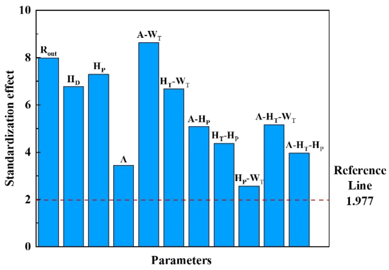
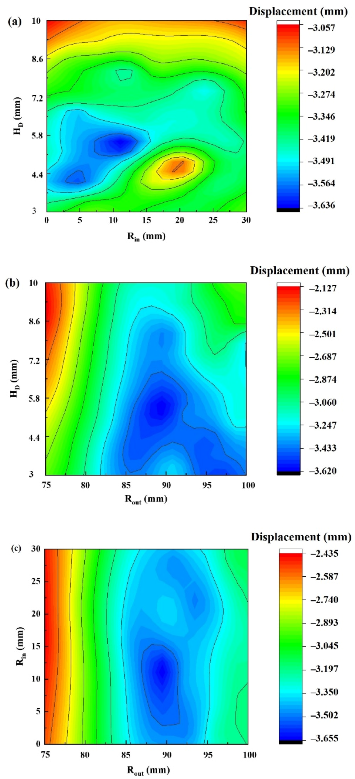
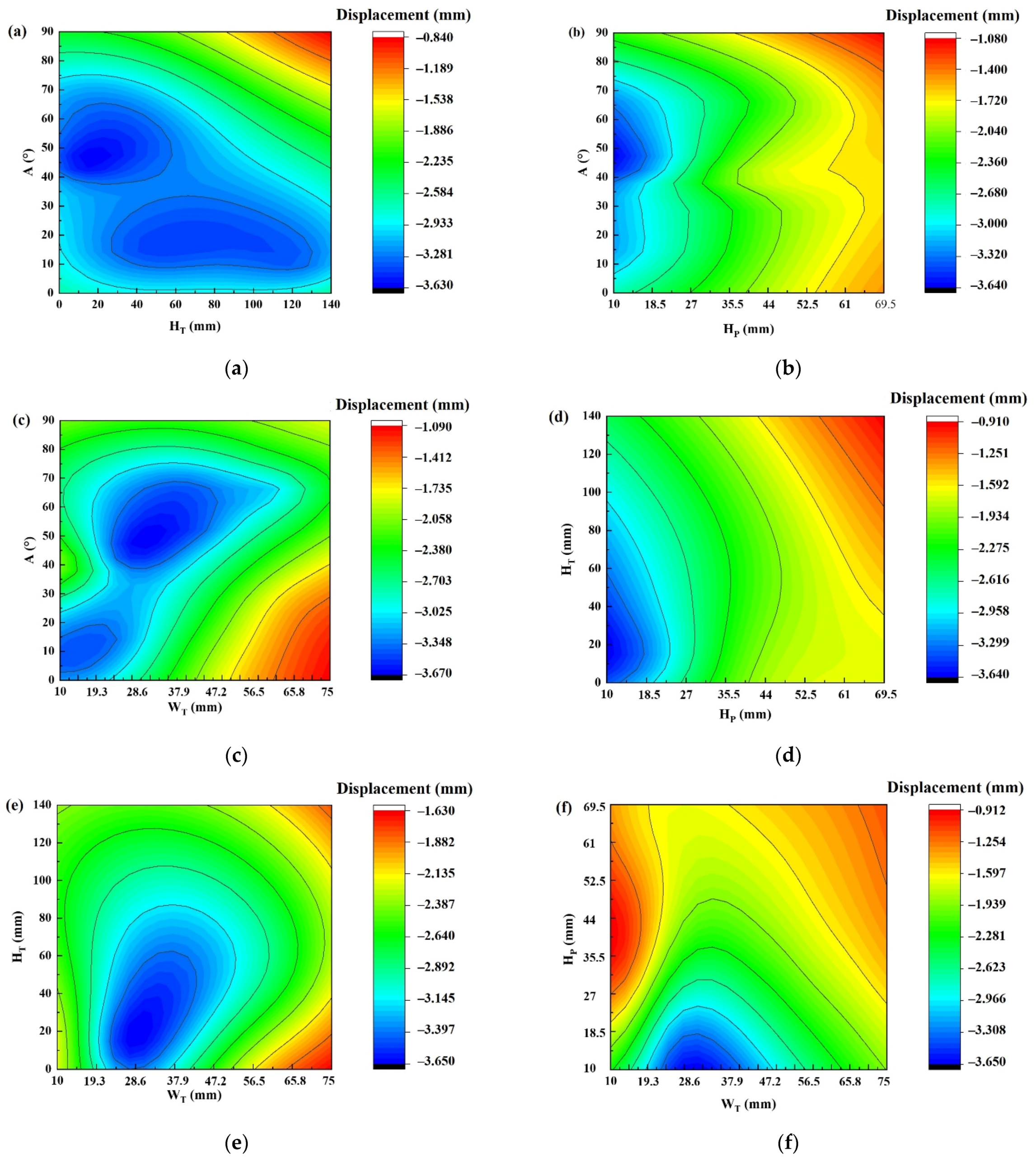
  • The RBF approximation analysis results based on the sequential numerical model showed that the outer diameter and the height of the driver plate had a significant first-order effect on the response of displacement. Meanwhile, the platform height, transition zone height, angle, and transition zone width of amplifier presented a strong interaction effect.
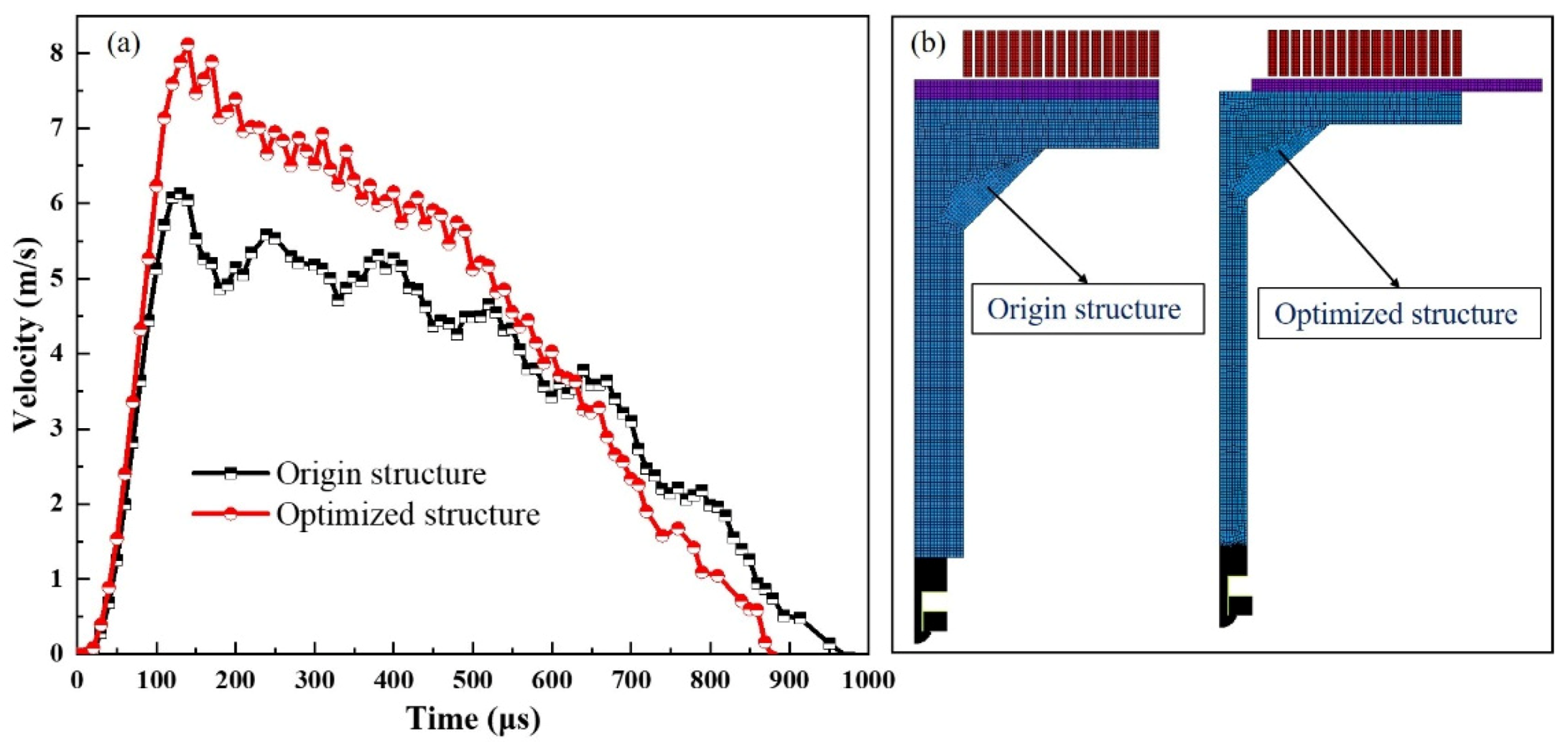
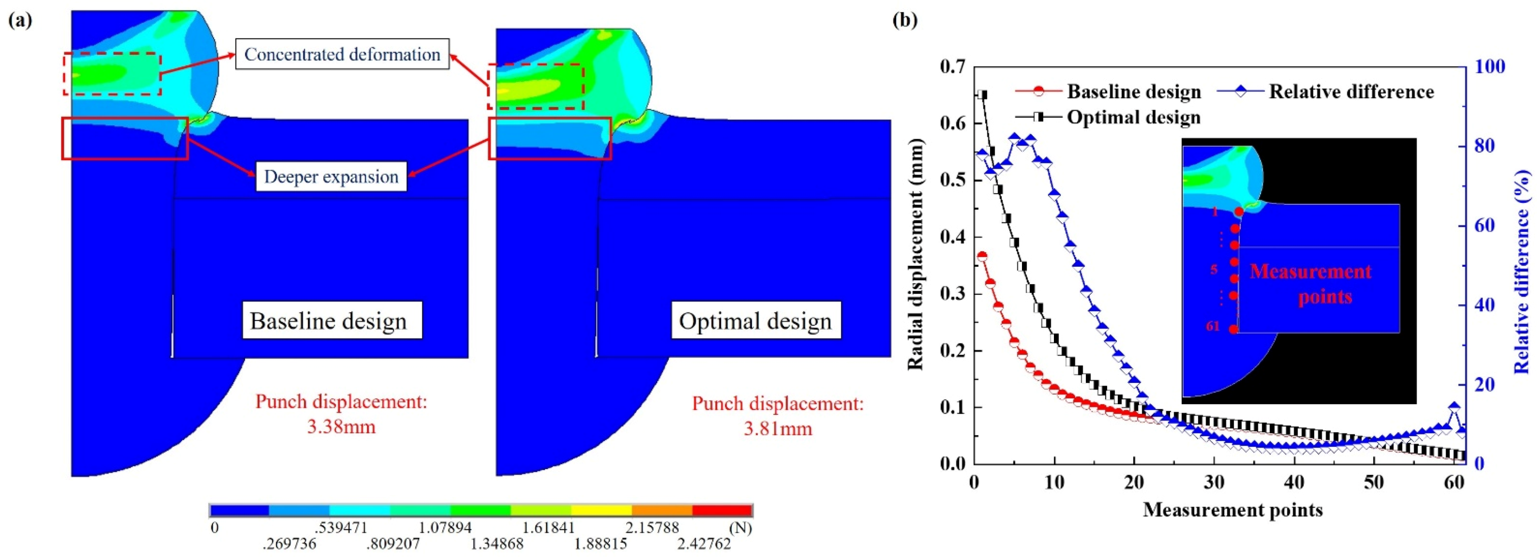
  • The optimal structural parameters of the driver plate and amplifier were obtained based on the parameter optimization model. It was found that the optimal design could effectively improve the velocity of the punch from 6.13 to 8.12 m/s with a 32.46% increase. In addition, the displacement of punch increasing from 3.38 to 3.81 mm would lead to an 80.55% increase in the maximum radial displacement of the rivet shaft. This indicated the deformation of the rivet was efficiently improved by using the optimal rivet model.

Author Contributions

Conceptualization, Y.Q.; methodology, Y.Q. and Y.L.; software, Y.Q.; validation, Y.Q. and Y.L.; formal analysis, G.L.; investigation, G.L.; resources, J.C.; data curation, H.J.; writing—original draft preparation, Y.Q.; writing—review and editing, H.J.; visualization, Y.Q.; supervision, H.J.; project administration, J.C.; funding acquisition, J.C. All authors have read and agreed to the published version of the manuscript.

Funding

This project is supported by the National Natural Science Foundation of China (Grant Nos. 52005173 and 51975202), China National Postdoctoral Program for Innovative Talents (BX20200123), State Key Laboratory of Advanced Design and Manufacturing for Vehicle Body Open fund of Hunan University (32065009) and Changsha Municipal Natural Science Foundation (kq2014047).

Institutional Review Board Statement

Not applicable.

Informed Consent Statement

Not applicable.

Data Availability Statement

The raw/processed data required to reproduce these findings cannot be shared at this time due to technical or time limitations.

Conflicts of Interest

The authors declare no conflict of interest.

Nomenclature

SymbolUnitMeaning
EMR-Electromagnetic Riveting Process
EMF-Electromagnetic Force
RBF-Radial Basis Function
CFRP-Carbon Fiber Reinforced Polymer
RLC-Resistor-Inductor-Capacitor
ASBs-The Adiabatic Shear Bands
FEM-Finite Element Model
DIC-Digital Image Correlation
RinmmInner Diameter of Driver Plate
RoutmmOuter Diameter of Driver Plate
HDmmHeight of Driver Plate
HPmmHeight of Platform
HTmmHeight of Transition Zone
A°Angle
WTmmWidth of Transition Zone

References

  1. Cui, J.J.; Dong, D.Y.; Zhang, X.; Huang, X.D.; Lu, G.X.; Jiang, H.; Li, G.Y. Influence of thickness of composite layers on failure behaviors of Carbon Fiber Reinforced Plastics/Aluminum alloy electromagnetic riveted lap joints under high-speed loading. Int. J. Impact Eng. 2018, 115, 1–9. [Google Scholar] [CrossRef]
  2. Huffer, B.W. HH54 rugged and reliable handheld EMR. Aerosp. Technol. Conf. Expo. 2009. [Google Scholar] [CrossRef]
  3. Hartmann, J.; Brown, T.; Pinkerton, B.; Nixon, K. Integration and Qualification of the HH500 Hand Operated Electromagnetic Riveting System on the 747 Section 11. In Wichita: SAE Aero Fast Conference; SAE International: Wichita, KS, USA, 1993. [Google Scholar]
  4. Feng, D.G.; Cao, Z.Q. Quality comparing analysis of electromagnetic riveting and pneumatic riveting. Forg. Stamp. Technol. 2012, 37, 123–126. [Google Scholar]
  5. Jiang, H.; Li, G.Y.; Zhang, X.; Cui, J.J. Fatigue and failure mechanism in carbon fiber reinforced plastics/aluminum alloy single lap joint produced by electromagnetic riveting technique. Compos. Sci. Technol. 2017, 152, 1–10. [Google Scholar] [CrossRef]
  6. Cao, Z.Q.; Cardew-Hall, M. Interference-fit riveting technique in fiber composite laminates. Aerosp. Sci. Technol. 2006, 10, 327–330. [Google Scholar] [CrossRef]
  7. Jiang, H.; Cong, Y.J.; Zhang, J.S.; Wu, X.H.; Li, G.Y.; Cui, J.J. Fatigue response of electromagnetic riveted joints with different rivet dies subjected to pull out loading. Int. J. Fatigue 2019, 129, 105238. [Google Scholar] [CrossRef]
  8. Bielawski, R.; Kowalik, M.; Suprynowicz, K.; Rządkowski, W.; Pyrzanowski, P. Investigation of Riveted Joints of Fiberglass Composite Materials. Mech. Compos. Mater. 2016, 52, 199–210. [Google Scholar] [CrossRef]
  9. Jiang, H.; Luo, T.; Li, G.Y.; Zhang, X.; Cui, J.J. Fatigue life assessment of electromagnetic riveted carbon fiber reinforce plastic/aluminium alloy lap joints using Weibull distribution. Int. J. Fatigue 2017, 105, 180–189. [Google Scholar] [CrossRef]
  10. Li, F.Q.; Mo, J.H.; Li, J.J.; Huang, L.; Zhou, H.Y. Formability of Ti-6Al-4V titanium alloy sheet in magnetic pulse bulging. Mater. Des. 2013, 52, 337–344. [Google Scholar] [CrossRef]
  11. Jiang, H.; Sun, L.Q.; Liang, J.S.; Li, G.Y.; Cui, J.J. Shear failure behavior of CFRP/Al and steel/Al electromagnetic self-piercing riveted joints subject to high-speed loading. Compos. Struct. 2019, 230, 111500. [Google Scholar] [CrossRef]
  12. Jiang, H.; Zeng, C.C.; Li, G.Y.; Cui, J.J. Effect of locking mode on mechanical properties and failure behavior of CFRP/Al electromagnetic riveted joint. Compos. Struct. 2020, 257, 113162. [Google Scholar] [CrossRef]
  13. Jiang, H.; Liao, Y.X.; Gao, S.; Li, G.Y.; Cui, J.J. Comparative study on joining quality of electromagnetic driven self-piecing riveting, adhesive and hybrid joints for Al/steel structure. Thin Walled Struct. 2021, 164, 107903. [Google Scholar] [CrossRef]
  14. Zhang, X.; Zhang, M.Y.; Sun, L.Q.; Li, C.F. Numerical simulation and experimental investigations on TA1 titanium alloy rivet in electromagnetic riveting. Arch. Civ. Mech. Eng. 2018, 18, 887–901. [Google Scholar] [CrossRef]
  15. Jiang, H.; Hong, Z.B.; Li, G.Y.; Cui, J.J. Numerical and experiment investigation on joining process and failure behaviors of CFRP/Al electromagnetic riveted joint. Mech. Adv. Mater. Struct. 2020. [Google Scholar] [CrossRef]
  16. Reinhall, P.G.; Ghassaei, S.; Choo, V. An analysis of rivet die design in electromagnetic riveting. J. Vib. Acoust. Stress Reliab. Des. 1988, 110, 65–69. [Google Scholar] [CrossRef]
  17. Repetto, E.A.; Radovitzky, R.; Ortiz, M.; Lundquist, R.C.; Sandstrom, D.R. A finite element study of electromagnetic riveting. J. Manuf. Sci. Eng. Trans. ASME 1999, 121, 61–68. [Google Scholar] [CrossRef] [Green Version]
  18. Zhang, X.; Zhu, C.C.; Hu, L.; Wu, H.Q.; Li, C.F. Investigations on microstructure evolution of TA1 titanium alloy subjected to electromagnetic impact loading. Arch. Civ. Mech. Eng. 2019, 19, 639–647. [Google Scholar] [CrossRef]
  19. Cui, X.H.; Mo, J.H.; Xiao, S.J.; Du, E.H.; Zhao, J. Numerical simulation of electromagnetic sheet bulging based on FEM. Int. J. Adv. Manuf. Technol. 2011, 57, 127. [Google Scholar] [CrossRef]
  20. Lee, S.H.; Lee, D.N. A finite element analysis of electromagnetic forming for tube expansion. J. Eng. Mater. Technol. 1994, 116, 250–254. [Google Scholar] [CrossRef]
  21. Wang, L.; Chen, Z.Y.; Li, C.X.; Huang, S.Y. Numerical simulation of the electromagnetic sheet metal bulging process. Int. J. Adv. Manuf. Technol. 2006, 30, 395–400. [Google Scholar] [CrossRef]
  22. Bartels, G.; Schatzing, W.; Scheibe, H.P.; Leone, M. Comparison of two different simulation algorithms for the electromagnetic tube compression. Int. J. Mater. Form. 2009, 1, 693–696. [Google Scholar] [CrossRef]
  23. Yu, H.P.; Li, C.F.; Deng, J.H. Sequential coupling simulation for electromagnetic–mechanical tube compression by finite element analysis. J. Mater. Process. Technol. 2009, 209, 707–713. [Google Scholar]
  24. Cui, J.J.; Qi, L.; Jiang, H.; Li, G.Y.; Zhang, X. Numerical and experimental investigations in electromagnetic riveting with different rivet dies. Int. J. Mater. Form. 2018, 11, 839–853. [Google Scholar] [CrossRef]
  25. Cui, J.J.; Zeng, C.C.; Jiang, H.; Li, G.Y. Flat Spiral Coil Design for Higher Riveting Force and Energy Saving in the Electromagnetic Riveting Process. J. Manuf. Sci. Eng. 2019, 141, 101014. [Google Scholar] [CrossRef]
  26. Qin, Y.F.; Jiang, H.; Cong, Y.J.; Li, G.Y.; Qi, L.; Cui, J.J. Rivet die design and optimization for electromagnetic riveting of aluminium alloy joints. Eng. Optim. 2020. [Google Scholar] [CrossRef]
  27. Mamalis, A.G.; Manolakos, D.E.; Kladas, A.G. Electromagnetic forming tools and processing conditions: Numerical simulation. Mater. Manuf. Process. 2006, 21, 411–423. [Google Scholar] [CrossRef]
  28. Chen, M. Research on Mechanical Properties Test and Dynamic Material Model of Ti6Al4V Titanium Alloy. Master’s Thesis, Nanjing University of Aeronautics and Astronautics, Nanjing, China, 2012. [Google Scholar]
  29. Zhao, M.; Cui, W.C. Application of the optimal Latin hypercube design and radial basis function network to collaborative optimization. J. Mar. Sci. Appl. 2007, 3, 24–32. [Google Scholar] [CrossRef]
  30. Sonar, D.K.; Dixit, U.S.; Ojha, D.K. The application of a radial basis function neural network for predicting the surface roughness in a turning process. Int. J. Adv. Manuf. Technol. 2006, 27, 661–666. [Google Scholar] [CrossRef]
  31. Kansa, E.J. Motivation for Using Radial Basis Functions to Solve PDEs; Lawrence Livermore National Laboratory and Embry-Riddle Aeronautical University: Daytona Beach, FL, USA, 1999. [Google Scholar]
  32. Park, J.S. Optimal Latin-Hypercube Designs for Computer Experiments. J. Stat. Plan. Inference 1994, 39, 95–111. [Google Scholar] [CrossRef]
  33. Duan, L.B.; Li, G.Y.; Chen, A.G.; Sun, G.Y.; Song, K. Multi-objective System Reliability-Based Optimization Method for Design of a Fully Parametric Concept Car Body. Eng. Optim. 2017, 49, 1247–1263. [Google Scholar] [CrossRef]
Figure 1. Flow chart of the EMR simulation model: (a) loose-coupled method; (b) sequential-coupled method.
Coatings 11 00878 g001
Figure 2. Schematic of the EMR simulation model: (a) loose-coupled; (b) sequential-coupled.
Coatings 11 00878 g002aCoatings 11 00878 g002b
Figure 3. Discharge current and current dispersion in simulation: (a) discharge current; (b) current dispersion.
Coatings 11 00878 g003
Figure 4. Quasi-static tensile stress-strain curves of AA5052 and AA6082 aluminum alloy: (a) AA5052; (b) AA6082.
Coatings 11 00878 g004
Figure 5. The diagram of the EMR equipment and impact velocity measuring equipment: (a) EMR equipment; (b) impact velocity measuring equipment; (c) riveting diagram.
Coatings 11 00878 g005
Figure 6. The element morphing results in the electromagnetic analysis using two algorithms: (a) loose-coupled model; (b) sequential-coupled model.
Coatings 11 00878 g006
Figure 7. The current density results in the electromagnetic analysis using two algorithms: (a) loose-coupled model; (b) sequential-coupled model.
Coatings 11 00878 g007
Figure 8. The temporal distribution of EMF on the driver plate in the loose-coupled model: (a) t = 10 μs; (b) t = 80 μs; (c) t = 260 μs; (d) t = 440 μs; (e) t = 620 μs; (f) t = 800 μs.
Coatings 11 00878 g008
Figure 9. The temporal distribution of EMF on the driver plate in the sequential-coupled model: (a) t = 10 μs; (b) t = 80 μs; (c) t = 260 μs; (d) t = 440 μs; (e) t = 620 μs; (f) t = 800 μs.
Coatings 11 00878 g009
Figure 10. Comparison of the magnetic–time force at a special point (r = 60 mm) between loose and sequential coupling algorithms.
Coatings 11 00878 g010
Figure 11. The impact velocity of the punch in the loose and sequential coupled models.
Coatings 11 00878 g011
Figure 12. Rivet deformation comparison between the numerical simulation and metallographic microstructure in two simulation approaches: (a) loose coupling method; (b) sequential coupling method; (c) radial displacement comparison between two methods.
Coatings 11 00878 g012
Figure 13. Configuration of the driver plate and amplifier of the EMR.
Coatings 11 00878 g013
Figure 14. Topology diagram of RBF.
Coatings 11 00878 g014
Figure 15. Contour map of the driver plate geometry on punch displacement: (a) HD and Rin (Rout = 75 mm); (b) HD and Rout (Rin = 10 mm); (c) Rin and Rout (HD = 5.5 mm).
Coatings 11 00878 g015
Figure 16. Contour map of the amplifier geometry on punch displacement: (a) A and HT (HP = 10 mm, WT = 30 mm); (b) A and HP (HT = 20 mm, WT = 30 mm); (c) A and WT (HP = 10 mm, HT = 20 mm); (d) HT and HP (WT = 30 mm, A = 45°); (e) HT and WT (HP = 10 mm, A = 45°); (f) HP and WT (HT = 20 mm, A = 45°).
Coatings 11 00878 g016
Figure 17. Pareto effect of the parameters in driver plate and amplifier.
Coatings 11 00878 g017
Figure 18. History of the y-velocity of the punch, and a diagram of driver plate and amplifier under EMR before and after optimization: (a) the velocity–time curve; (b) diagram of the structure.
Coatings 11 00878 g018
Figure 19. Comparison of the EMF distribution between baseline and optimal design: (a) baseline design; (b) optimal design.
Coatings 11 00878 g019
Figure 20. The comparison of equivalent strain in rivet and radial displacement in the rivet shaft between baseline and optimal design: (a) equivalent strain in rivet; (b) radial displacement in the rivet shaft.
Coatings 11 00878 g020
Table 1. The elements used in modeling the electromagnetic field.
EntityElement TypeDOFs
Driver platePLANE13Ax, Ay, Volt
CoilPLANE13Ax, Ay, Volt
AirPLANE13Ax, Ay
Far fieldINFIN110Ax, Ay
Specifically, Ax means the freedom in the x direction; Ay means the freedom in the y direction; Volt means the freedom in the voltage calculation.
Table 2. Discharge circuit parameters of the EMR system.
Inductance
(L)/H
Resistance
(R)/Ω
Attenuation
Coefficient
(β)/s−1
Oscillatory
Frequency
(ω)/(rad⋅s−1)
Capacitance
(C)/F
7.8 × 10−64.35 × 10−22.79 × 1031.77 × 104408 × 10−6
Table 3. Material properties used in simulating the electromagnetic and structural fields.
MaterialMagnetic PermeabilityResistivity (Ω·m)Elastic
Modulus (Pa)
Poisson RatioDensity
(kg/m3)
Yield Stress (Pa)Tangent Modulus (Pa)mp (s−1)
AA505212.7 × 10−825.1 × 1090.332800100.8 × 106379 × 1060.256500
AA608212.7 × 10−866 × 1090.332800240 × 106261 × 1060.256500
Ti-6Al-4V142 × 10−888 × 1090.3445001009 × 1064527 × 1060.2617247,640
Steel146 × 10−8210 × 1090.287850----
Cu11.72 × 10−8-------
Air/Far field1--------
Specifically, m and p was the multiplier constant of Cowper–Symonds model.
Table 4. Geometric design space of the driver plate and amplifier of EMR.
ParameterLower BoundUpper BoundBase
Rout75 mm100 mm75 mm
Rin0 mm30 mm0 mm
HD3 mm10 mm6 mm
HP10 mm70 mm15 mm
A90°45°
HT0 mm140 mm25 mm
WT10 mm75 mm40 mm
Table 5. Optimal values for the structural parameters of the driver plate and amplifier.
ParameterHDRinRoutHPAHTWT
Values4 mm10 mm100 mm10 mm48°23 mm34 mm
Publisher’s Note: MDPI stays neutral with regard to jurisdictional claims in published maps and institutional affiliations.

