Article

The Effect of Polytetrafluoroethylene (PTFE) Particles on Microstructural and Tribological Properties of Electroless Ni-P+PTFE Duplex Coatings Developed for Geothermal Applications

by
Gifty Oppong Boakye
1,
Arna María Ormsdóttir
1,
Baldur Geir Gunnarsson
1,
Sandeep Irukuvarghula
2,
Raja Khan
2 and
Sigrún Nanna Karlsdóttir
1,*
1
Mechanical Eng. and Computer Science, Faculty of Industrial Eng., University of Iceland, Hjardarhagi 2-6, Reykjavík, Iceland
2
TWI Ltd., Granta Park, Cambridge CB21 6AL, UK
*
Author to whom correspondence should be addressed.
Coatings 2021, 11(6), 670; https://doi.org/10.3390/coatings11060670
Submission received: 21 April 2021 / Revised: 23 May 2021 / Accepted: 26 May 2021 / Published: 1 June 2021
(This article belongs to the Special Issue Coatings Challenges in Harsh Environments)

Abstract

:
The selection of electroless nickel-phosphorus plating (ENP) has been inclined towards their properties and advantages with complex geometry applications. These properties include coating uniformity, low surface roughness, low wettability, high hardness, lubricity, and corrosion- and wear-resistance. Materials used in geothermal environments are exposed to harsh conditions such as high loads, temperature, and corrosive fluids, causing corrosion, scaling, erosion and wear of components. To improve the corrosion- and wear-resistance and anti-scaling properties of materials for geothermal environment, a ENP duplex coating with PTFE nanoparticles was developed and deposited on mild steel within the H2020 EU Geo-Coat project. ENP thin adhesive layer and ENP+PTFE top functional layer form the duplex structure of the coating. The objective of this study was to test the mechanical and tribological properties of the developed ENP-PTFE coatings with varying PTFE content. The microstructural, mechanical and tribological properties of the as-deposited coating with increasing PTFE content in the top functional layer in the order: ENP1, ENP2 and ENP3 were evaluated. The results showed maximum wear protection of the substrates at the lowest load; however, increasing load and sliding cycles increased the wear rates, and 79% increased lubrication was recorded for the ENP2 duplex coating. The wear performance of ENP3 greatly improved with a wear resistance of 8.3 × 10⁴ m/mm3 compared to 6.9 × 10⁴ m/mm3 for ENP2 and 2.1 × 10⁴ m/mm3 for ENP1. The results are applicable in developing low friction, hydrophobic or wear-resistive surfaces for geothermal application.

1. Introduction

Electroless nickel plating (ENP) is a conventional deposition method that involves a chemical reduction of Ni2+ from an aqueous solution onto metallic substrates. Placing a coating of a nickel-phosphorus alloy (Ni-P) on a surface is the commonest form of ENP plating. The low-to-high phosphorous material, which typically ranges from 3 to 14 wt% [1], has a significant effect on the deposited electroless nickel-phosphorous layer properties. ENP offers a broad application spectrum via its inherent high coating uniformity, good adhesion, low roughness, high hardness, and corrosion- and wear-resistant properties. Furthermore, it is possible to enhance the mechanical and tribological properties by adding particles as reinforcements to optimize their industrial efficiency [1,2,3,4].
The concept of reinforcement is to adjust the wide-range performance of the ENP coatings to achieve specific desired properties. In literature, the common co-deposition processes with either or both soft and hard particles developed over time include: SiO2, Al2O3, ZrO2, TiO2, Mo, MoS2, PTFE, Diamond, CNT, SiC, CNT-SiC, Si3N4, WC, ZnO, B4C, BN, TiN [3,5,6,7,8,9,10,11,12]. The target application areas include microelectromechanical systems (MEMS), textile, foundry tools, automotive, aerospace, membrane reactors, and heat exchanger units [3]. In tribology, the addition of hard particles creates a hard and wear-resistant composite coating, whereas soft, solid lubricants result in a film with self-lubricating and excellent anti-stick properties [5].
Fluoropolymers (CFx) such as PTFE have low-temperature curability, hydrophobic properties, chemical inertness and thermal stability of up to 350 °C, and are often used for oil and gas coating applications [13,14]. The feasibility of incorporating the PTFE second- phase particles within the ENP matrix at relatively low temperatures and low curing time produces a synergistic advantage of the different properties of the Ni-P alloy and PTFE polymer. The surface energy range of 22 to 28 mN/m can be achieved through the Ni metal properties with the low surface energy of PTFE [15]. The material becomes hydrophobic (as low surface energy limits wettability), offering minimal microbial and anti-scaling properties, decreasing the likelihood of scaling [14] and corrosion [16]. Since PTFE has cryogenic properties and a relatively high melting point compared to the other polymers, ENP+PTFE composite coatings were applied and used in heating and cooling systems up to 290 °C [3]. Besides improved thermal conductivity [17], it also has a lower friction and energy wear rate [16,18], therefore, it could be used in areas of wear from high speeds but low contact loads or in the presence of abrasive materials such as silica scales. This indicates the composite coating could potentially provide protection in boilers, separators, condensers, and safety and pumping systems in geothermal plants.
Few studies have reported a negative impact on film quality because of the dynamic relationship between surface and mass transport during the plating processes for the ENP+PTFE compared to ENP [19]. Several researchers studying ENP technology with particle inclusion found that the ability to achieve (1) uniform particle dispersion (herein PTFE) and (2) good composite adhesion to the substrate is crucial for the coating durability, corrosion and wear performance [20,21,22,23]. Therefore, for this study, a duplex coating was fabricated considering the reviewed merits and demerits of the plating process and properties of ENP deposits. An ENP undercoat is deposited to boost coating adhesion onto a steel substrate. PTFE is embedded into the top functional layer of the same composition ENP to form a composite coating of ENP+PTFE. This study aims to improve adhesion to mild steel and assess the tribological properties as a function of different PTFE content in the top coating layer to establish potential application in geothermal power generation systems. For instance, seals, valves, and impellers are subject to friction and wear in the steam production, transmission, and reinjection systems, resulting in leaks due to poor sealing and diameter reduction from material loss. Meanwhile, in addition to avoiding delamination during high-temperature operations, the top functional layer of the duplex coating on a heat exchanger unit will mitigate challenges with drag, pressure drop, heat transfer, and abrasive wear from entrapped particles/periodic mechanical washing.
The focus of this research is to characterize the ENP duplex coatings with varying amounts of PTFE, and test the mechanical and tribological properties in an effort to develop ENP coatings where the duplex (top + undercoat) provides good protection against wear. The functionalized topcoat is expected to influence surface properties by improving friction and wear-resistance. The critical performance of the coating was evaluated against the resultant microstructural, wettability, and mechanical and tribological properties for coatings with different PTFE material content to optimize the required PTFE concentration in the duplex coatings.

2. Materials and Methods

2.1. Sample Surface Preparation

Mild steel discs (50 mm diameter) were degreased in hot alkaline solution (~50 °C) for 15 min followed by rinsing in de-ionized (DI) water. They were then etched in hot (~50 °C) H2SO4 solution to remove the surface oxide layer. Once the oxide layer was removed and acid traces were removed by dipping into de-ionized water, the specimens were quickly transferred into an ENP bath.

2.2. Bath Preparation and Electroless Ni-P+PTFE Composite Coating

All chemicals were of analytical grade and purchased from Sigma Aldrich and Fisher Scientific. PTFE particles, due to their hydrophobic nature, cannot be dispersed homogeneously in water. PTFE particles and F-C4 cationic surfactant portions were mixed in DI water by mechanical stirring for 2–3 h. After that, the solution was subjected to ultrasonic treatment for 3 h. This step de-agglomerated the PTFE particles and produced a homogeneous aqueous dispersion. This was verified using the dynamic light scattering approach to measure their particle size distribution (PSD) (instrument: Malvern ZetaSizer Nano-S, Waltham, MA, USA). The average size of PTFE particles was about 307 nm, yielding a unimodal distribution. Furthermore, efforts were made to minimize defects by optimizing the amount of surfactant (0.1–0.5 g/L) to create aqueous dispersion of PTFE. All ENP were performed in a fume hood. A nickel ion source (NiSO4 × 6H2O (g/L)), reducing agent (NaH2PO2 × H2O (g/L)), complexing agent (C6H5Na3O7 × 2H2O (g/L)), accelerator (NH4CH3COO (g/L)), stabilizer (CH4N2S (ppm)), and pH regulator (NH4OH/CH3COOH (%)) was employed to streamline the operating conditions of the ENP bath. The amount of chemicals used in the bath was determined by the amount of phosphorus targeted in the Ni-P layer. Since the objective was to produce duplex coatings (i.e., Ni-P undercoat followed by Ni-P+PTFE top coat), the etched specimens were first transferred into Ni-P bath for producing undercoat. After 15 min, the samples were removed and quickly transferred into another Ni-P bath that contained dispersion of PTFE particles within the solution. The samples were immersed in the bath for 60 min after which they were removed and thoroughly cleaned using DI water and dried using a hot air gun. Both undercoat and topcoat depositions were performed at 85–90 °C, with pH being maintained around 5.5. Three types of ENP duplex coated samples were prepared to contain low, medium, and high PTFE content and referred to herein as ENP1, ENP2 and ENP3. The undercoat contained no PTFE while the Ni-P deposits contained medium P content in all cases. Table 1 and Table 2 summarize the PTFE content used in the preparation of the coatings and the concentrations of major chemicals used in the plating process.

2.3. Testing and Characterisation of Coatings

The microstructure, surface morphology and coating thickness were conducted by scanning electron microscopy (FE-SEM, Zeiss Supra 25® Oberkochen, Germany). The SEM was equipped with an energy dispersive X-ray spectrometer (EDS, Oxford Instruments®, Oxford, UK) used for the elemental and compositional analysis of the selected regions of the coatings. The X-ray diffraction (XRD) was performed in an X-Pert Pro with Cu Kα Radiation (λ = 1.5406 Å). The Kruss Drop Shape Analysis system (DSA 100® Hamburg, Germany) was used to calculate contact angles using the sessile drop method. This equipment determines a surface’s wettability by water to predict hydrophobic properties or fouling potential. The contact angle was calculated using the DSA software from 10 different locations. Roughness measurements were carried out with a Taylor Hobson Ametek stylus profilometer to determine the topological surface parameters such as Ra. The steps and measurements were in line with the standard DIN/ISO 4287. Profilometry images of the surfaces after the test were obtained using an optical profiler (Solarius® SD-V100-3219, San Jose, CA, USA). The hardness of the coatings was obtained from 12 different locations along the cross-section with Vickers micro-hardness tester (VH1202 Wilson®, Esslingen, Germany) using 0.05 kg-f load for 15 s. The friction and wear setup, procedure and measurements followed the ASTM G99 standard [24]. The tribological sliding test was done with a ball-on-disc configuration using pin-on-disk tribometer (Anton Paar® TRB3, Graz, Austria). The stationary counterpart was a chromium steel (100Cr6) ball of 6 mm diameter. The applied load was in the range of 2 to 10 N and the test duration was for 1 h. During the tests, the radius of the wear track was varied between 5 mm and 20 mm for each sample, with the corresponding linear velocity (cm/s) variations depending on the total number of tests and distance (m) covered. The coefficient of friction was determined by monitoring the evolution of the tangential force at dry sliding contact and dividing it by the applied load. The specific wear rate, wsample (mm3/Nm), was evaluated according to Equation (1) by measuring the volume of the removed material, V (mm3), and using the applied load, Fn (N), and the distance covered during testing, L (m):
w sample = V / F n × L   [ mm 3 / Nm ]
The mild steel substrate and the 304 L stainless steels were also tested and analyzed for comparison according to the previously explained procedure. The study uses 304 L SS as the reference material because it is one of the most widely used materials in plant construction, especially for heat exchangers. The objective is to show that 304 L can be replaced by ENP coated mild steel to save money and extend service life in geothermal applications.

3. Results

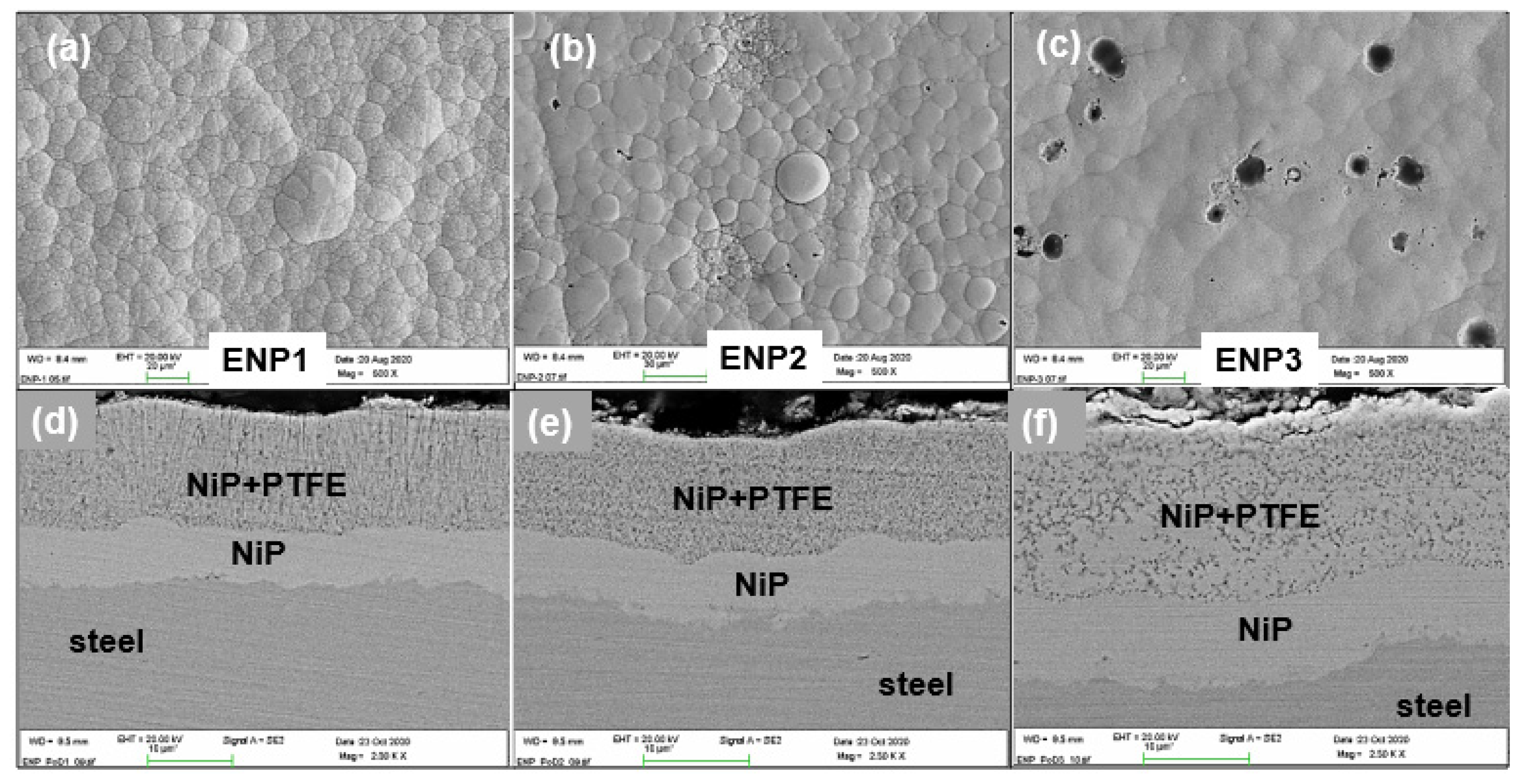
3.1. Morphology and Structure of the Duplex Coatings

Figure 1 shows the surface morphology and cross-sectional micrographs of the different ENP+PTFE duplex coatings. The coatings were observed with globular particles, similar to the conventional morphology for ENP coatings [17]. The distribution of F, indicative of PTFE (C2F4), was homogeneous on the outer surfaces and entrapped in the interior and between grains in the coatings. From Figure 1a, a finer multiple grain structure was obtained for high Ni-to-low PTFE content coatings at a microscopic level. With increasing PTFE, the grains enlarged, yielding a less rugged morphology but visible nano-holes/pores in the top surface seen in Figure 2b,c. This morphology is explained by the decreasing Ni and P concentration (Table 3) and growth kinetics with PTFE addition to the coating. This is evident in Figure 1b,c, where the nano-pores are visible, introduced due to PTFE incorporation and the hydrogen gas evolution and escape during coating processes.
The cross-section micrographs in Figure 1d,e,f reveal the microstructure of the duplex coatings. All the coatings appear dense, continuous and with no obvious pores, but the Ni-P+PTFE layer had dark spots indicative of the nano-PTFE reinforcing phase. The ENP3 had non-uniform dispersion of the PTFE (areas free of dark spots in Figure 1f) in the layers nearer to the substrate. This indicates that depositing 15 g/L of PTFE did not increase PTFE incorporation in the matrix concurrently during plating. Moreover, Table 3 reports a lower wt% F for the ENP3 from the elemental maps of the surfaces of the different coatings given in Figure 2. According to the electroplating theory [25,26], the decrease in F could be clarified by an insufficient cationic surfactant (g/L) to promote the dispersion of the PTFE particles. On the other hand, using PTFE > 10 g/L (ENP3) resulted in a supersaturated plating solution, which accumulated PTFE in areas near the substrate and suppressed the effective diffusion of PTFE particles to the interface, hence the free spots in the matrix. All the coatings had a thickness of approximately 5 ± 1 µm for Ni-P undercoat and 20 ± 5 µm for Ni-P+PTFE topcoat. A good adhesion was observed between the coating-substrate and the coating-coating interface due to the Ni-P interlayer. No defects or damages were visible at the interfaces.

3.2. Phase Composition of the Coatings

In Figure 3a, the XRD graph shows the phase composition of the ENP+PTFE duplex coatings in the as-plated condition whereas Figure 3b shows the XRD patterns of medium P electroless Ni-P undercoat deposits (i.e., without any PTFE particle dispersion) with low P and high P to complement the results in order to understand the microstructural changes occurring in the layers of the duplex. The results are consistent with the SEM and EDS analyses, where the peaks identified to represent the same elements as detected in the coating. The microstructure of as-plated ENP coatings has similarly been reported by Fayyad et al. [27] as crystalline for low Ni-P (1–5 wt%) and amorphous for high Ni-P (10–12 wt%). The peaks of the duplex coatings in Figure 3a showed crystalline structures and amorphous structures to a certain extent, as well as peaks from the substrate (Fe). In the ENP1 duplex coating, the Ni peak at 44.5° was comparatively highly amorphous. However, the crystalline structure in ENP2 and ENP3 revealed additional amorphous Ni structures. The amorphous Ni was limited to coatings with PTFE ≥ 10 g/L, with the peak broadening observed for the reflections around 52° and 76°.
Further examination of Table 3 shows that the elemental surface analysis of the ENP1, ENP2 and ENP3 topcoat contained approximately 5.3, 3.2 and 3.0 wt% phosphorus, respectively. Thus, in the pattern, the medium P content in both the undercoat and topcoat (with PTFE in the Ni-P matrix) accounted for the mixed amorphous-crystalline structures of ENP2 and ENP3 duplex coatings. The refined grains confirmed from the calculated crystallite size from Scherrer’s equation [23] caused broader peak diffraction in ENP1, indicative of an amorphous Ni-P coating. The crystallite size of the Ni-P increased with increased PTFE dispersion of the order 43.6 nm, 58.2 nm, 69.8 nm for ENP1, ENP2 and ENP3, respectively. The crystallization peak of PTFE was observed at a diffraction angle of 18. The PTFE peak was prominent in both ENP2 and ENP3. Although there is no chemical interaction of the PTFE with the Ni-P alloy since the nanoparticles are only embedded in the matrix, the plating conditions influenced crystallization. This is evident in the Ni ((111) – FCC) peak at 44.5° in ENP2 and ENP3, which turned microcrystalline with the increased PTFE content used in the fabrication. Therefore, the microstructure of the ENP1 is amorphous, whereas that of the ENP1 and ENP2 coating tends to be a mixed crystalline-amorphous structure (see Figure 3).

3.3. Surface Roughness and Water Contact Angle (WCA) Analysis of the Coatings

The surface structures, morphology and topography of the coatings greatly influence the roughness and wettability of coatings. Figure 4 compares the water contact angle (WCA) and arithmetic average surface roughness parameter (Ra) of the different coatings. The WCA for ENP1, ENP2, ENP3 are 94.1° ± 0.89, 102.6° ± 0.70, and 93.9° ± 2.49, and the Ra values are 1.24 ± 0.11 µm, 1.72 ± 0.08 µm, and 2.16 ± 0.21 µm, respectively. The Ra of the ENP+PTFE duplex coatings increased with higher PTFE content and large grain size. ENP3 recorded the highest Ra and highest surface energy (wettability), while ENP2 demonstrated the least wettability at 102.6° with water. Therefore, it could be said that the Ra was not only influenced by pre-treatment of the surface but also the globular grain size with PTFE particle addition. In contrast, the effective distribution of the nanoparticles in the matrix was significant for the hydrophobicity of the coatings.

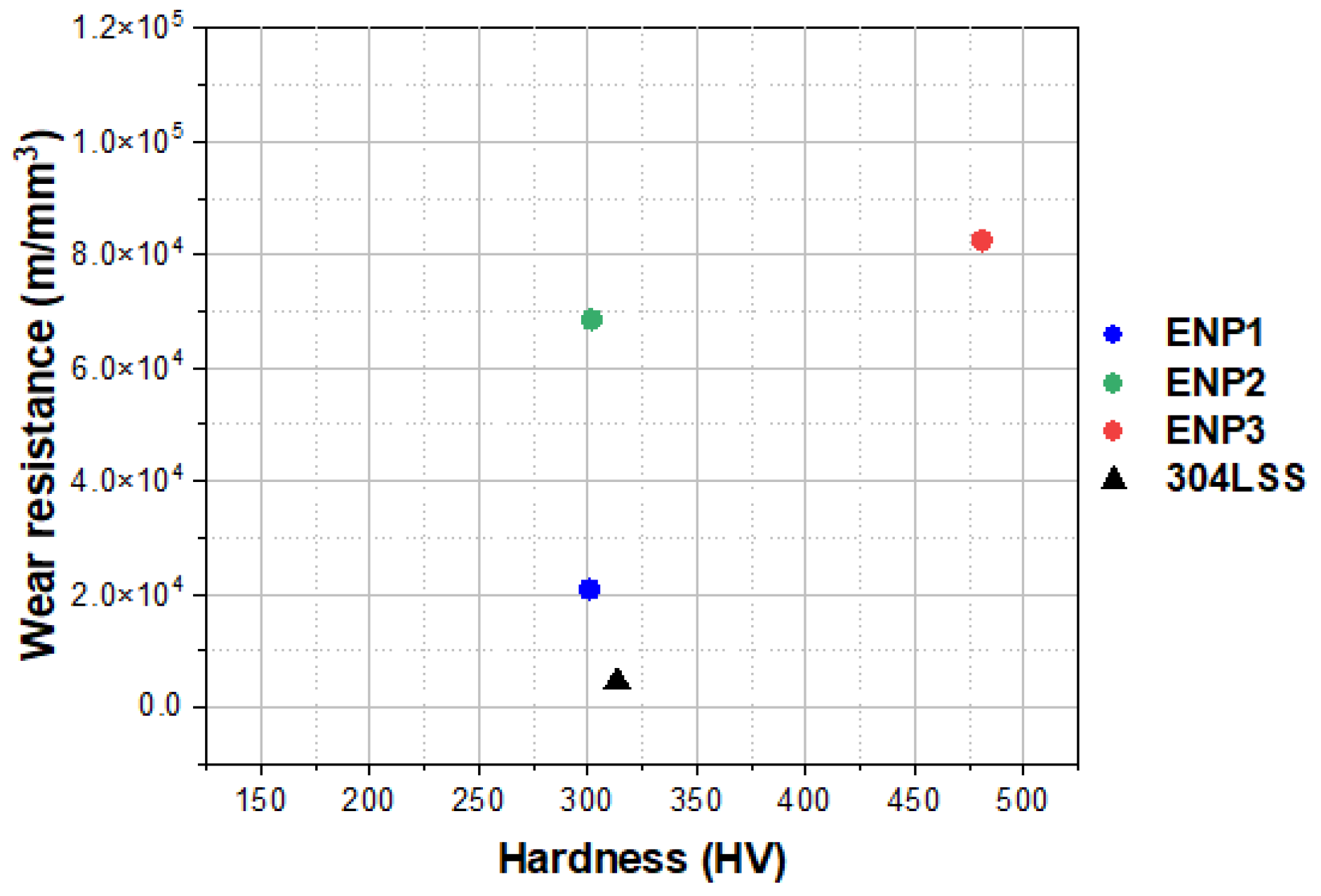
3.4. Microhardness Analysis of the Coatings

Generally, friction and wear have been attributed and influenced by properties such as surface roughness, stiffness, and hardness of two materials in relative motion. The microhardness of the coatings was determined since microstructural changes were observed in the XRD analysis with PTFE addition. Figure 5 shows the obtained hardness of the coatings after 12 indentations, with increased hardness measured for the ENP+PTFE coatings compared to the mild steel substrate measured as 163.1 ± 0.2 HV. The mean microhardness was 300.7 ± 37, 301.8 ± 27 and 480.8 ± 51.8 HV. The hardness of the coatings increased with increasing PTFE content, contrary to other literature [25,27], which defined PTFE as a softer polymer.
Further examination of the EDS findings (in Table 1) reveals that ENP1 represented the least amount of F (3.1 wt%) but had a hardness value comparable to ENP2 (9.2 wt% F). This suggests the variation in hardness of the duplex coating was dependent on PTFE dispersion in the Ni-P matrix. Accordingly, the microhardness of as-plated ENP coating is reported between 500 and 550 HV for Ni-P alloy with no PTFE fillers [25,28,29]. Similar to the non-uniformly distributed PTFE coating (i.e., ENP3 in this work), the coating with free spots in the Ni-P matrix (due to PTFE particle agglomeration) yielded the highest hardness value (i.e., 400–550 HV) with a broad standard deviation. This explains the disparity in increasing hardness between this work and other literature.

3.5. Tribological Properties

For optimizing the individual tribological performances, a dry wear test was carried out with coefficient of friction (CoF) and wear rate as the performances’ index. Figure 6 shows friction evolution with sliding time for the different duplex coatings against a 100Cr6 steel ball under the different loads. The shape of the curves exhibits some stages, which depicts the overall friction-time behavior. The stages are associated with running-in (i.e., the onset of the sliding period before steady-state) and stick-slips (see Figure 6a), which observed a series of steps in the steady region in the curves. The higher the load, the shorter the running-in time. Higher shear motion and multiple occurrences of friction spikes in the plots at such loads (as seen in Figure 6b—0.5 h test) indicate stick-slip behavior dependent on the physical or chemical nature of the surface [30], which was most visible in ENP1 and ENP3.
Meanwhile, the CoF of the ENP2 coatings was smooth, low and steady. This behavior suggests a well-lubricated tribosystem maintaining a balance in each test condition of the average kinetic friction, wear rates, lubrication debris concentration, and surface roughness. The friction-related transitions for the other coatings, on the other hand, were discontinuous and triggered by test parameters, PTFE nanoparticles’ lubrication effect, Ni-P undercoat interfacial processes, and substrate stresses. For instance, the PTFE nanoparticles and Ni-P matrix’s friction contribution are apparent in the 2 N-1 h curves (Figure 6c), showing two regions with continuous increase in friction coefficient of the coatings after the onset of sliding even for the ENP2. This is because the softer PTFE is removed first where a film formation in the contact controls lubrication. The corresponding mean values of CoF at the 2 N-1 h test were 0.37, 0.47 and 0.58 for ENP1, ENP2 and ENP3, respectively. In comparison, the friction value for Ni-P alloy with no fillers was reported to be 0.68 [23]. In ENP1, the interfacial Ni-P (undercoat) with moderate friction effect was visible after the film loss (i.e., the transfer seen in the 5N curve in Figure 6b). However, in the 10 N-1 h test, higher friction evolved when the substrate was locally reached (with the pull-outs seen in Figure 6a). In this study, ENP2 produced a decreased friction coefficient of 79% at the highest load and sliding cycles corresponding to the value 0.17 compared to 0.81 for the 304 L reference material. This suggests that the ENP2 duplex coatings can potentially be a candidate as coating material to reduce wear in components used in geothermal power plants.
Figure 7 presents the average coefficient of friction values of the different coatings under the various test loads. Although ENP1 contained lower PTFE content, better friction performance was recorded compared to ENP3, suggesting film formation in the tribo-contacts for ENP1. The film acts as a transfer, so-called tribolayer, formed from the mixed fluorine and oxygen debris (from initial wear of the coating) that cushions the surface at increasing load and repetitive cycles. The film loss can confirm this at the 10 N-1 h test, where ENP3 outperformed ENP1. From the friction curves, the film loss in the ENP1 contact resulted in surface galling and pull-outs down to the sub-surface while a steady-state was finally reached for the ENP3 coating.
Comparing the wear results obtained under the different loads, the wear coefficient of the duplex coatings was of the same order of magnitude (i.e., 10−5). The obtained material loss and specific wear rates after testing are plotted in Figure 8a,b, respectively. The wear volume was normalized with the different test loads and sliding distance; thus, the highest value was observed at 2N load. No measurable material removal was observed for ENP2 and ENP3 at the lowest loads, signifying maximum wear protection by the coating. This suggested that the microstructure, preferably to the hardness of the ENP3 coating, had a major impact on the friction and wear properties. Furthermore, this hypothesis is confirmed by the sparing values between the wear-resistance (see Figure 9), considering the similar hardness of the ENP1 and ENP2 coatings. The highest volume loss was recorded for increasing load and sliding time as expected. The surfaces of the ENP1 coatings had the highest material removal and wear rates.
ENP3 had the lowest wear volume and wear rates at higher sliding cycles and loads, in contrast to the friction results. Under the test loads, the wear performance of the finer-grained ENP1 coating was approximately 4–5 times that of the reference steel, 14–30 times for ENP2, and 15–27 times for ENP3. The incorporation of PTFE in the Ni-P+PTFE composite coating has been reported to produce similar results in other studies [12,15,20] but reports of lower wear rates exhibited larger sub-surface scuffing (i.e., the substrate of single layer deposit) [31]. Comparatively, the wear rate of a single layer deposit reported by Rahmati and Mahboobi [15] with similar PTFE composition as the duplex analyzed in this paper was reduced to 43% and 66% for ENP2 (10 g/L) and ENP3 (15 g/L), respectively. The authors attributed increased wear rate of the single layer ENP3 (15 g/L) to adhesive failure at the substrate and cohesive failure within the ENP+PTFE composite. As a result, the Ni-P interlayer could have been significant for the observed wear performance of the ENP3 duplex coating, which was influenced by the improved adhesion and between the substrate and composite coating, as well as the inherent increase in thickness associated with double layer deposition.
Figure 9 compares the wear-resistance (1/wear rate) [32] as a function of hardness of the ENP+PTFE duplex coatings compared to reference 304 L stainless steel at the highest test load of 10N. The wear-resistance is independent of the load; thus, the worn volumes with the sliding conditions were used. The developed coatings had outstanding performance compared to the 304 L SS. The best performance was observed for the electroless-nickel coating ENP3 with increasing grain size and improved Ni-P coating structures. Therefore, for wear-resistive properties, the preferable concentration of the PTFE reinforcement must be greater than 5 g/L in the electroless plating solution with efficient dispersion.

4. Discussion

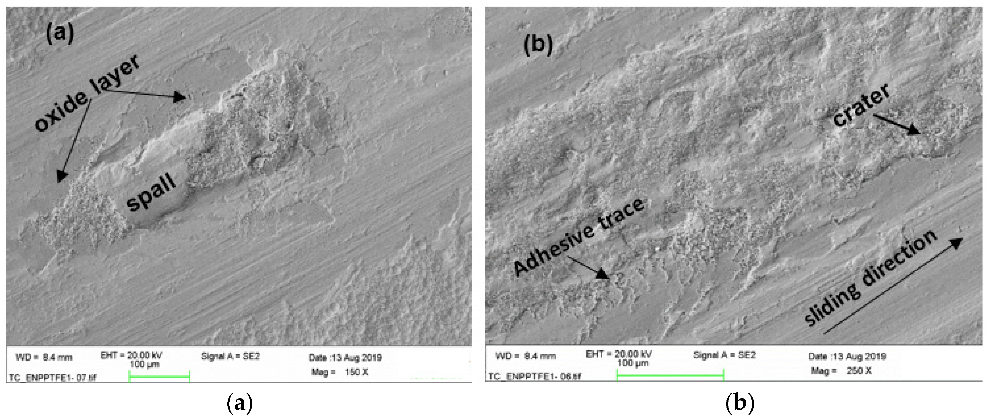
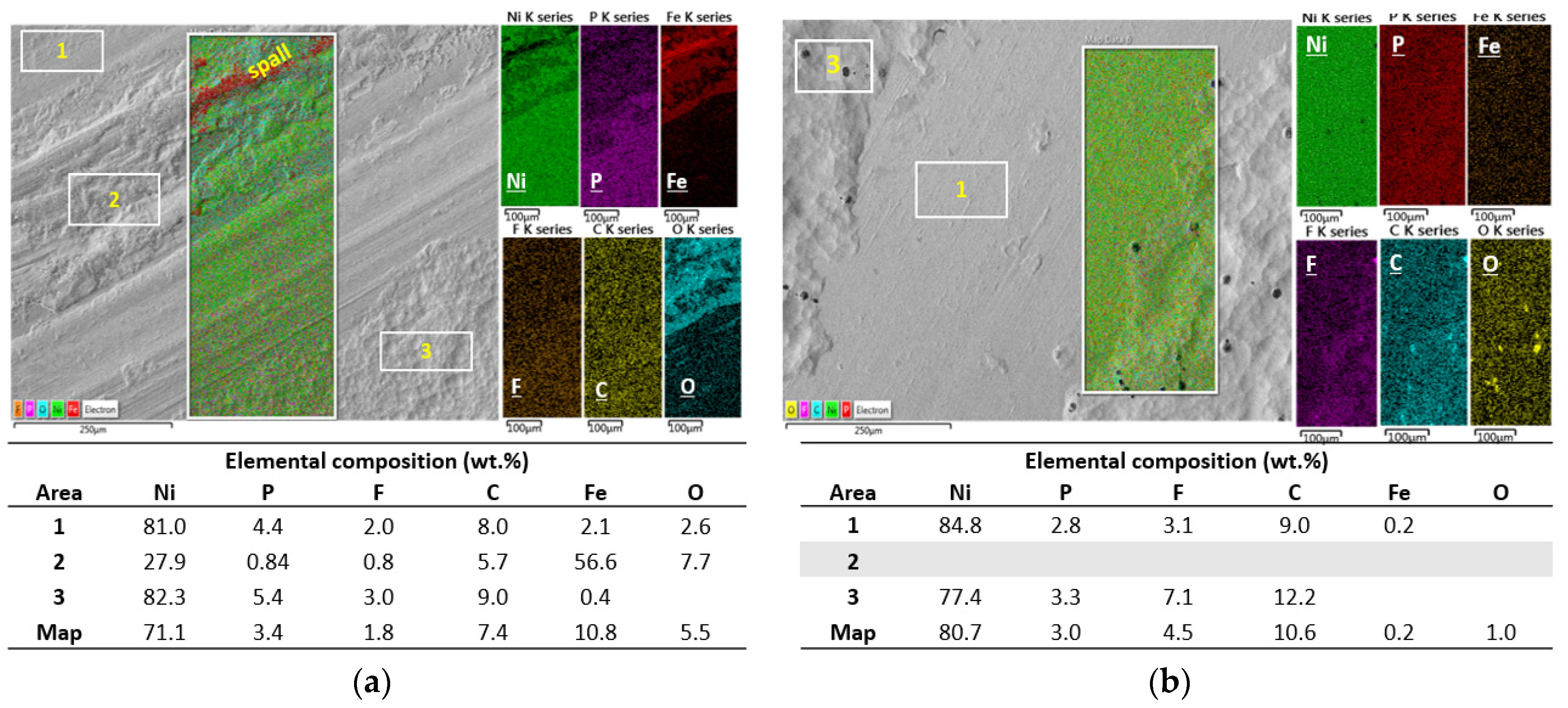
Lubrication and Wear Mechanism

Overall, the mechanism was supported by the running-in evolution of friction coefficient that produced increased wear in the contact, forming a mixed oxide-PTFE film from the wear debris. After few cycles of lower friction (≈0.15–0.6), progressive increment occurs with damage or total removal of the transfer film. Figure 10 shows schematics of the proposed hypothesis on the effects of the fabrication process, with introduction of compressive stresses from the deposition parameters of Ni and microstructural alteration with the increase in PTFE content on increased wear-resistance duplex coatings. The schematics in Figure 11 explain our hypothesis on the transition of wear occurring for the coatings during the tests. The wear behavior can be explained partially by the film behavior and the contact conditions at the ball interface. The friction remained stable for higher amounts of PTFE (ENP2 and ENP3) and showed no significant reduction, whereas for low amounts (ENP1), friction rapidly increased. However, the SEM micrographs and profilometry images from Figure 11, Figure 12 and Figure 13 show variation in surface appearance (surface irregularities) as a function of PTFE. This suggests that the film formation and duration on the surfaces did not follow the same behavior. The transfer film is smooth and continuous; thus, these conditions reduce the time to achieve stability seen in the ENP2 duplex coatings. Therefore, irrespective of the coating composition and microstructure, the transfer film complicates material loss within the tribo-contact arising from surface irregularities. Thus, after surface analysis, an intermediate state of wear could be described under mild to higher loading and sliding conditions, explaining the higher friction values at such loads.
In a continuous sequence from Figure 11a,b, if PTFE particles removed from the bulk did not attach to the steel counter body but were lost from the system, a clean surface is observed, and wear is minimal. However, in Figure 11c, the counter face experiences abrasive-adhesive wear, producing mixed metal oxide material when the debris is entrapped/picked up, increasing friction and wear. For instance, the deposited layer in ENP3 in Figure 13c (5 N-1 h test) gave rise to wear regions in the profilometry image in Figure 12f with a deeper wear depth of 6.51 µm compared to 2.44 µm for the ENP2 coating. The least worn surfaces had a shallow depth of wear and relatively smooth average roughness with the contrast shown in Figure 11. ENP1 showed the highest material loss from the surface, while the lowest rate was found in ENP3. The microstructure and hardness of the ENP3 coating had a major impact on the friction and wear properties. This is because, despite the non-uniform dispersion of the PTFE in the matrix, the hardness of the Ni-P matrix confers high abrasion resistance to the coatings.
The SEM results of ENP2 and ENP3 show fine scratches and third body effects (picked-up oxide layer) visible on all the coating surfaces. To provide valuable wear information, Figure 13 was beneficial in determining the two-failure mechanisms present:
(1)
the smoothing by plastic deformation from gradual abrasion of the Ni-P+PTFE top layer and
(2)
the fatigue wear of only ENP1 due to high internal stresses via spalling [31].
The amorphous and multiple fine grains of the ENP1 coatings explain the already strained state of the Ni-P+PTFE duplex coating. Whereas the lower P content, microcrystalline Ni peak in the XRD and coarsened grains from entrapment of the PTFE particles may have been a source of compressive stress reducing the stresses in the ENP2 and ENP3 duplex, resulting in an improved microstructure (depicted in Figure 11). Furthermore, with the intrinsic stresses in ENP1, the expectations of a soft and ductile FCC matrix and the deformation mechanism of the amorphous structure (i.e., with no grain boundaries), the pull-outs and spalling in Figure 14 can easily be explained.
Moreover, increased addition of PTFE in ENP2 and ENP3 with the effect of low phosphorus produced a robust friction film hindering tip penetration since low phosphorus coatings have been reported with good frictional properties [33]. Thus, the absence of cracks, spalls, and debris in the ENP2 and ENP3 micrographs (Figure 13b,c,e,f). Further observation of the damages in ENP1 by SEM displayed significant delamination in the mid-regions and smooth/adhesive traces at the edge (Figure 14a,b). This is because of the high contact pressure in the center of the counterbody (steel ball), which falls to zero at the end. At lower cycles (0.5 h), the surface analysis showed picked-up oxide layers that cracked and spalled off (Figure 14a) due to its brittleness (hence it acted as the fatigue crack nucleation sites during sliding), producing the craters on the worn surface. With such delamination in central regions, the surfaces stick, whereas, around the annular areas, slip occurred, contributing to the mixed stick-slip condition for the ENP1 coating. On the other hand, in the friction curves of ENP3, the stick-slip phenomenon was related to thicker oxide patches with high-stress concentrations during sliding.
Figure 15 compares the surface chemistry of ENP1 and ENP3 coatings at the 10 N-1 h testing conditions. The SEM/EDS area spectrum 1, 2, 3, corresponds to less worn, highly worn and unworn areas of the test surface, respectively. The result shows a decrease in Ni in the wear tracks at locations 1 and 2 with increasing Fe (56.6 wt%) and O (7.7 wt%) content in the mid-track of ENP1 (scanned area 2). This is attributed to substrate wear and oxidation of the wear debris in the atmosphere. In ENP3, mild wear features were visible, showing only areas 1 and 3 in Figure 15b. Moreover, the concentration of F decreased by 9% compared to the initial composition of ENP3 before the wear test, suggesting a significant contribution of P and C2F4 to the enhanced tribological performance. The rim or edges of ENP1 (i.e., area 1) demonstrated similar wear features where minor wear occurred. The high Ni to low Fe content was complemented with higher C, F and P weight fractions at such spots. Comparatively to the center, wear was enhanced by the Ni-P topcoat and undercoat running against the steel ball apparent in the decreased (82.3 wt%) Ni- (5.4 wt%) P content in area 3 to (27.9 wt%) Ni- (0.84 wt%) P in area 2 of Figure 15a.

5. Conclusions

Duplex electroless nickel-phosphorus composite (ENP thin adhesive layer and ENP+PTFE top functional layer) coatings were developed from the dispersion of PTFE nanoparticles in different ENP baths. All the developed coatings outperformed the reference 304 L SS material with good wear-resistance at the applied load based on the following conclusions:
  • SEM/EDS and XRD analyses demonstrated the presence of PTFE particles. Significant changes in the coatings’ morphology and microstructure were observed to improve grain size, hydrophobicity, arithmetic average surface roughness, and hardness with PTFE addition. In the ENP solution, the ideal amount for PTFE homogenization was 10 g/L in this work.
  • In the tribological testing, the PTFE was responsible for the lubricating properties of the coatings. Independent of the coating composition and structure, PTFE positively influenced the formation of a robust transfer film eliminating stick-slip, high volume loss and adhesion in the tribo-contact. However, this property is a function of PTFE dispersion. In comparison to the reference 304 L SS, the ENP2 found a steady friction value of 0.17 with a 79% increase in lubricity at the highest test load and cycles.
  • The sporadic hardness values measured in the ENP3 coating confirmed the clustering effect of PTFE particles and affected steady-state friction-wear conditions. The cycles to steady-state friction occurred at the highest load and sliding cycles.
  • The worn zones of the coatings displayed smooth surfaces from fine abrasion or scratching, however, at higher loads and sliding cycles, ENP1 coating failed by galling and fatigue wear.
  • Finally, the coating with dispersed PTFE reduced surface energy by more than 100% compared to the substrate. Thus, the combination of low friction and low hydrophobicity suggests that the duplex coatings present good candidacy for drag, scaling and corrosion mitigation in heating and cooling units (e.g., heat exchangers) used in geothermal power plants. Furthermore, ENP2 (10 g/L PTFE) is optimum for both low friction and wear applications at low contact load, while ENP3 (15 g/L PTFE) has desirable wear resistances but compromised lubrication under dry contact sliding (due to non-uniform dispersion and agglomeration of PTFE in the matrix).

Author Contributions

Data curation, G.O.B. and S.I.; Investigation, G.O.B., A.M.O., B.G.G. and S.I.; Supervision, S.N.K. and R.K.; Writing—original draft, G.O.B.; Writing—review & editing, S.I., R.K. and S.N.K. All authors have read and agreed to the published version of the manuscript.

Funding

This work was part of the H2020 EU Geo-Coat project. This project received funding from the European Union’s Horizon 2020 research and innovation program under grant agreement number 764086.

Institutional Review Board Statement

Not applicable.

Informed Consent Statement

Not applicable.

Data Availability Statement

Not applicable.

Acknowledgments

The authors would also like to acknowledge the resources and collaborative efforts provided by the consortium of the Geo-Coat project.

Conflicts of Interest

The authors declare no conflict of interest.

References

  1. Buchtík, M.; Kosár, P.; Wasserbauer, J.; Tkacz, J.; Doležal, P. Characterization of Electroless Ni–P Coating Prepared on a Wrought ZE10 Magnesium Alloy. Coatings 2018, 8, 96. [Google Scholar] [CrossRef] [Green Version]
  2. Sudagar, J.; Lian, J.; Sha, W. Electroless nickel, alloy, composite and nano coatings—A critical review. J. Alloy. Compd. 2013, 571, 183–204. [Google Scholar] [CrossRef] [Green Version]
  3. Balaraju, J.N.; Narayanan, T.S.N.S.; Seshadri, S.K. Electroless Ni–P composite coatings. J. Appl. Electrochem. 2003, 33, 807–816. [Google Scholar] [CrossRef]
  4. Krick, B.A.; Ewin, J.J.; Blackman, G.S.; Junk, C.P.; Sawyer, W.G. Environmental dependence of ultra-low wear behavior of polytetrafluoroethylene (PTFE) and alumina composites suggests tribochemical mechanisms. Tribol. Int. 2012, 51, 42–46. [Google Scholar] [CrossRef]
  5. Sahoo, P.; Das, S.K. Tribology of electroless nickel coatings—A review. Mater. Des. 2011, 32, 1760–1775. [Google Scholar] [CrossRef]
  6. Gutsev, D.; Antonov, M.; Hussainova, I.; Grigoriev, A.Y. Effect of SiO2 and PTFE additives on dry sliding of NiP electroless coating. Tribol. Int. 2013, 65, 295–302. [Google Scholar] [CrossRef]
  7. Karthikeyan, S.; Ramamoorthy, B. Effect of reducing agent and nano Al2O3 particles on the properties of electroless Ni–P coating. Appl. Surf. Sci. 2014, 307, 654–660. [Google Scholar] [CrossRef]
  8. Tang, A.; Wang, M.; Huang, W.; Wang, X. Composition design of Ni–nano-Al2O3–PTFE coatings and their tribological characteristics. Surf. Coatings Technol. 2015, 282, 121–128. [Google Scholar] [CrossRef]
  9. Mukhopadhyay, A.; Barman, T.K.; Sahoo, P.; Davim, J.P. Comparative study of tribological behavior of electroless Ni-B, Ni-B-Mo, and Ni-B-W coatings at room and high temperatures. Lubricants 2018, 6, 67. [Google Scholar] [CrossRef] [Green Version]
  10. Zhou, Y.-R.; Zhang, S.; Nie, L.-L.; Zhu, Z.-J.; Zhang, J.-Q.; Cao, F.-H.; Zhang, J.-X. Electrodeposition and corrosion resistance of Ni–P–TiN composite coating on AZ91D magnesium alloy. Trans. Nonferrous Met. Soc. China 2016, 26, 2976–2987. [Google Scholar] [CrossRef]
  11. Balaraju, J.N.; Seshadri, S.K. Synthesis and corrosion behavior of electroless Ni-P-Si3N4 composite coatings. J. Mater. Sci. Lett. 1998, 17, 1297–1299. [Google Scholar] [CrossRef]
  12. Mohammadi, M.R.; Ghorbani, M. Wear and corrosion properties of electroless nickel composite coatings with PTFE and/or MoS2 particles. J. Coat. Technol. Res. 2011, 8, 527–533. [Google Scholar] [CrossRef]
  13. Zhang, S. State-of-the-art of polymer tribology. Tribol. Int. 1998, 31, 49–60. [Google Scholar] [CrossRef]
  14. Keogh, W.; Boakye, G.O.; Neville, A.; Olsen, J.H.; Charpentier, T. Lead Sulfide (PbS) Scale Behavior and Deposition as a Function of Polymeric Sulfide Inhibitor Concentration in Multiphase. In Proceedings of the International Corrosion Conference and Expo Series 2018, Phoenix, ZA, USA, 15–19 April 2018. [Google Scholar]
  15. Rahmati, H.; Mahboobi, F. Studying the Effect of the Concentration of PTFE Nanoparticles on the Tribological Behavior of Ni-P-PTFE Composite Coatings. Iran. J. Oil Gas Sci. Technol. 2015, 4, 67–75. [Google Scholar]
  16. Tajbakhsh, M.; Yaghobizadeh, O.; Nia, M.F. Investigation of the physical and mechanical properties of Ni–P and Ni–P–PTFE nanocomposite coatings deposited on aluminum alloy 7023. Proc. Inst. Mech. Eng. Part E J. Process Mech. Eng. 2019, 233, 94–103. [Google Scholar] [CrossRef]
  17. Kinoshita, H.; Yonezawa, S.; Kim, J.; Kawai, M.; Takashima, M.; Tsukatani, T. Electroless Nickel-plating on PTFE fine particles. J. Fluor. Chem. 2008, 129, 416–423. [Google Scholar] [CrossRef]
  18. Balaji, R.; Pushpavanam, M.; Kumar, K.Y.; Subramanian, K. Electrodeposition of bronze–PTFE composite coatings and study on their tribological characteristics. Surf. Coat. Technol. 2006, 201, 3205–3211. [Google Scholar] [CrossRef]
  19. Sahoo, P. Tribological performance of electroless Ni-P coatings composite. In Materials and Surface Engineering; Woodhead Publishing: Swanston Cambridge, UK, 2012; pp. 163–205. [Google Scholar]
  20. Sheu, H.H.; Jian, S.Y.; Lin, M.H.; Hsu, C.I.; Hou, K.H.; der Ger, M. Electroless Ni-P/PTFE self-lubricating composite thin films applied for medium-carbon steel substrate. Int. J. Electrochem. Sci. 2017, 12, 5464–5482. [Google Scholar] [CrossRef]
  21. Huang, Y.; Zeng, X.; Hu, X.; Liu, F. Corrosion resistance properties of electroless nickel composite coatings. Electrochimica Acta 2004, 49, 4313–4319. [Google Scholar] [CrossRef]
  22. Sharma, A.; Singh, A.K. Electroless Ni-P-PTFE-Al2O3 dispersion nanocomposite coating for corrosion and wear resistance. J. Mater. Eng. Perform. 2014, 23, 142–151. [Google Scholar] [CrossRef]
  23. Sharma, A.; Singh, A.K. Corrosion and wear resistance study of Ni-P and Ni-P-PTFE nanocomposite coatings. Cent. Eur. J. Eng. 2011, 1, 234–243. [Google Scholar]
  24. American Society for Testing and Materials. ASTM G99-05, Standard Test Method for Wear Testing with a Pin-on-Disk Apparatus; American Society for Testing and Materials: Philadelphia, PA, USA, 2010. [Google Scholar]
  25. Liu, Y.; Zhao, Q. Study of PTFE content and anti-corrosion properties of electroless Ni-P-PTFE coatings. Plat. Surf. Finish. 2004, 91, 48–51. [Google Scholar]
  26. Srinivasan, K.N.; John, S. Studies on electroless nickel–PTFE composite coatings. Surf. Eng. 2005, 21, 156–160. [Google Scholar] [CrossRef]
  27. Fayyad, E.M.; Abdullah, A.M.; Hassan, M.K.; Mohamed, A.M.; Wang, C.; Jarjoura, G.; Farhat, Z. Synthesis, Characterization, and Application of Novel Ni-P-Carbon Nitride Nanocomposites. Coatings 2018, 8, 37. [Google Scholar] [CrossRef] [Green Version]
  28. Chen, S.Y.; Shi, Y.; Fan, H.; Liang, J.; Liu, C.S.; Sun, K. Synthesis of Ni-P-PTFE-nano-Al2O3 composite plating coating on 45 steel by electroless plating. J. Compos. Mater. 2012, 46, 1405–1416. [Google Scholar]
  29. Jiang, W.; Shen, L.; Wang, Z.; Wang, K.; Xu, M.; Tian, Z. Wear resistance of a Ni-PTFE composite coating strengthened with nano-SiC particles. Mater. Res. Express 2019, 6, 096443. [Google Scholar] [CrossRef]
  30. Blau, P. Effects of Tribosystem Variables on Friction. In Nondestructive Evaluation; CRC Press: Boca Raton, FL, USA, 2008; pp. 269–313. [Google Scholar]
  31. Ramalho, A.; Miranda, J. Friction and wear of electroless NiP and NiP+PTFE coatings. Wear 2005, 259, 828–834. [Google Scholar] [CrossRef]
  32. Hutchings, I.; Gee, M.; Santner, E. Friction and Wear. In Springer Handbook of Materials Measurement Methods, 1st ed.; Springer: Berlin/Heidelberg, Germany, 2006; pp. 685–710. [Google Scholar]
  33. Taheri, R.; Oguocha, I.; Yannacopoulos, S. The tribological characteristics of electroless NiP coatings. Wear 2001, 249, 389–396. [Google Scholar] [CrossRef]
Figure 1. SEM micrographs showing morphology (ac) and cross-sectional microstructure (df) of the deposited ENP1, ENP2 and ENP3 duplex coatings.
Coatings 11 00670 g001
Figure 2. SEM micrographs showing surface morphology and the corresponding elemental maps of (a) ENP1, (b) ENP2 and (c) ENP3.
Coatings 11 00670 g002
Figure 3. X-ray diffraction patterns of the deposited electroless (a) Ni-P matrix (i.e., MP) with embedded PTFE from the top surface (b) Ni-P undercoat (i.e., MP) of the ENP duplex coatings compared to LP and HP, along with the simulated patterns of nickel and the substrate. LP is low phosphorus, MP is medium phosphorus, and HP is high phosphorus.
Coatings 11 00670 g003
Figure 4. The water contact angle (WCA) and arithmetic average surface roughness parameter (Ra) of the deposited electroless ENP duplex coatings.
Coatings 11 00670 g004
Figure 5. The effect of PTFE content on microhardness of the deposited ENP+PTFE: ENP1, ENP2 and ENP3 duplex coatings.
Coatings 11 00670 g005
Figure 6. The evolution of coefficient of friction as a function of time at various loads and sliding cycles of the ENP+PTFE: ENP1, ENP2 and ENP3 duplex coatings.
Coatings 11 00670 g006
Figure 7. Influence of PTFE content on the average CoF values of the deposited electroless ENP+PTFE: ENP1, ENP2 and ENP3 duplex coatings at different loads.
Coatings 11 00670 g007
Figure 8. Volume loss from worn tracks (a) and wear rates (b) of the deposited electroless ENP+PTFE: ENP1, ENP2 and ENP3 duplex coatings at the different loads.
Coatings 11 00670 g008
Figure 9. Wear-resistance versus hardness of the ENP duplex coatings and 304 L SS reference material at 10N load after 12,000 cycles.
Coatings 11 00670 g009
Figure 10. Schematics of (a) the structure of the proposed duplex coating and (b) the effect of the plating process and optimized PTFE content on improved properties of the coatings for effective wear control.
Coatings 11 00670 g010
Figure 11. The transition in wear is proposed to have occurred by (a) high loss rate as the film formed with high friction (Figure 6: running-in friction of ENP1, ENP2 and ENP3), (b) much lower loss rate after the film formed where the tribo-system remained steady (i.e., constant friction and wear conditions; Figure 13b,e: ENP2 and Figure 13f: ENP3), and (c) higher loss rate from the film due to fragments (Figure 13a: ENP1) or total film loss due to cyclic sliding (Figure 13d: ENP1) and material gain on the hard coating from abrasive-adhesive wear of the steel counter body (Figure 13c: ENP3).
Coatings 11 00670 g011
Figure 12. 3D optical profilometry images of the worn tracks on the developed ENP+PTFE: ENP1, ENP2 and ENP3 duplex coatings at various loads and sliding cycles.
Coatings 11 00670 g012
Figure 13. SEM surface micrographs of the worn tracks from 5 N and 10 N test loads on the ENP+PTFE: ENP1, ENP2 and ENP3 duplex coatings at 12,000 sliding cycles.
Coatings 11 00670 g013
Figure 14. SEM morphology of worn zones of the developed ENP1 duplex coating at 10N load for duration of: (a) 6000 cycles-0.5 h and (b) 12,000 cycles-1 h.
Coatings 11 00670 g014
Figure 15. SEM morphology of wear surfaces and EDS maps of the worn zones of the developed ENP+PTFE: (a) ENP1 and (b) ENP3 duplex coatings at 10 N load for a duration of 1 h-12,000 cycles.
Coatings 11 00670 g015
Table 1. A Summary of The Plating Characteristics Used in ENP Duplex Layer Development.
Plating MethodUndercoat Ni-P *Topcoat Ni-P+PTFE *Sample ID
P Content (wt%)P (wt%) PTFE (g/L)
Bath 1medium Medium5ENP1
Bath 2MediumMedium10ENP2
Bath 3MediumMedium15ENP3
* The amount of PTFE and P content (i.e., 6–8 wt%) used in the fabrication of the duplex coating.
Table 2. Key Chemicals and Their Quantity (per liter) Used for Preparing ENP Baths.
ChemicalRange
Nickel sulphate (NiSO4 × 6H2O)0.1–0.11 M
Sodium hypophosphite (NaH2PO2 × H2O)0.19–0.28 M
Sodium citrate (C6H5Na3O7 × 2H2O)0.035 M
Acetic acid/ammonium hydroxide (NH4OH/CH₃COOH)pH~5.5–6.2
Table 3. The Elemental Composition of the Surface Maps in Figure 2 of the Ni-P with Embedded PTFE Duplex Coating.
Surface Analysis Ni-P+PTFENiPCF
wt%at%wt%at%wt%at%wt%at%
ENP181.854.95.36.79.832.03.16.4
ENP276.746.63.23.710.932.59.217.2
ENP372.338.83.03.017.846.76.911.5
Publisher’s Note: MDPI stays neutral with regard to jurisdictional claims in published maps and institutional affiliations.

