
Effects of Roughness on Stresses in an Oxide Scale Formed on a Superalloy Substrate


Abstract
:1. Introduction
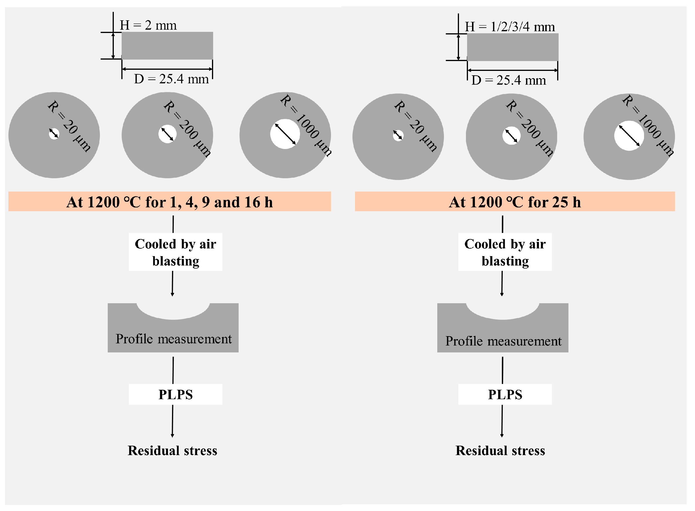
2. Experiments
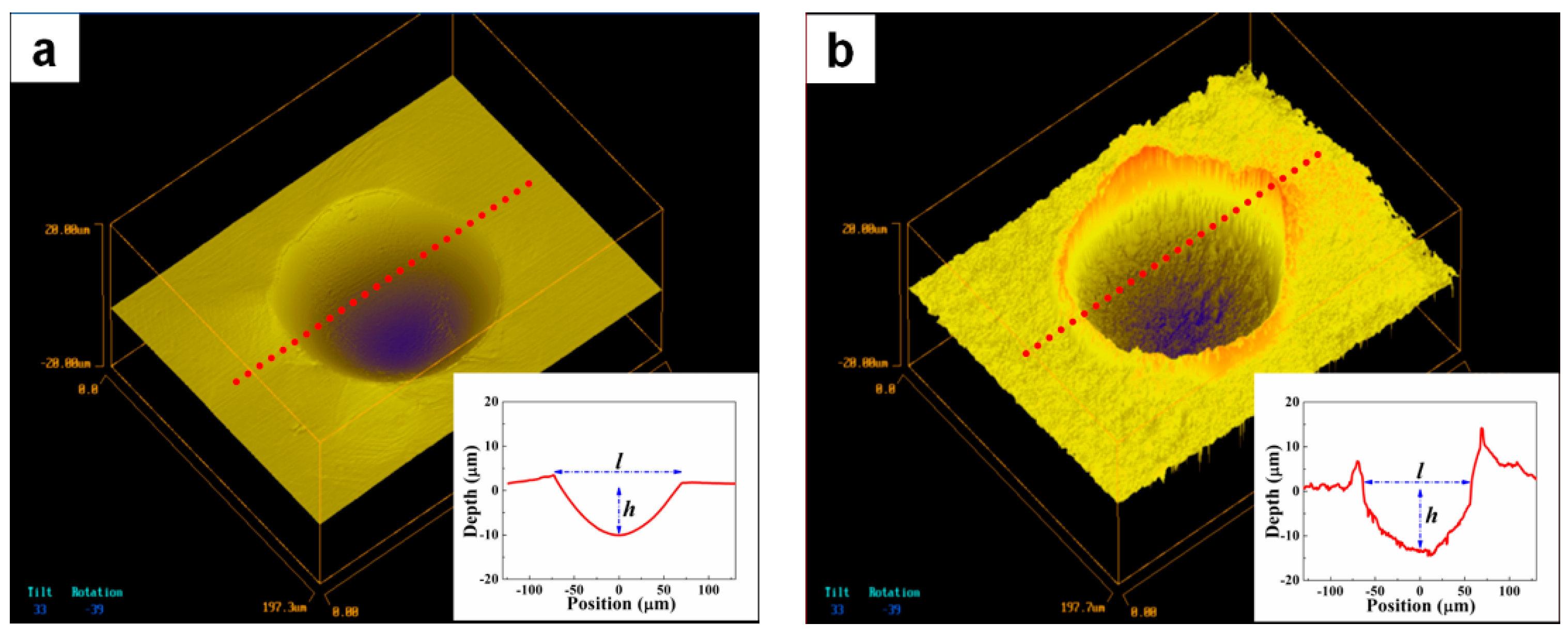
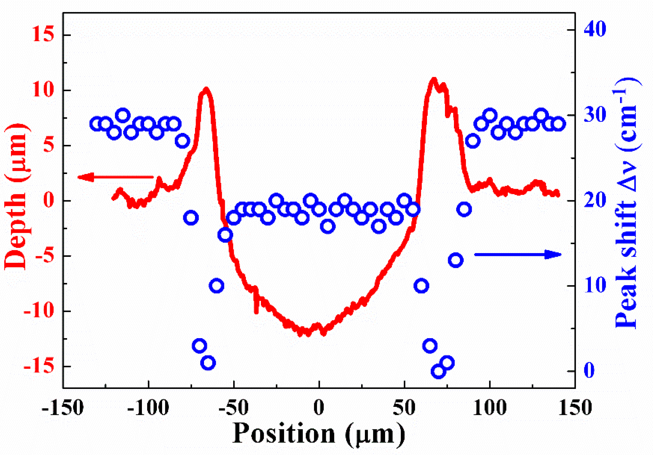
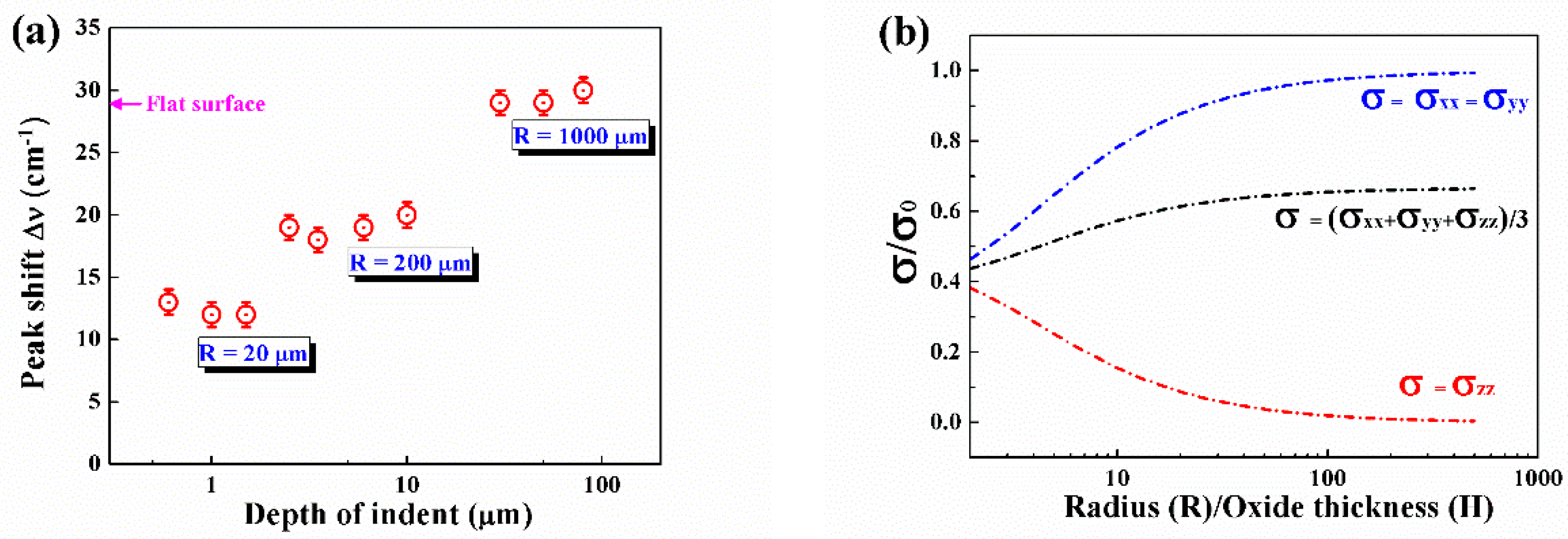
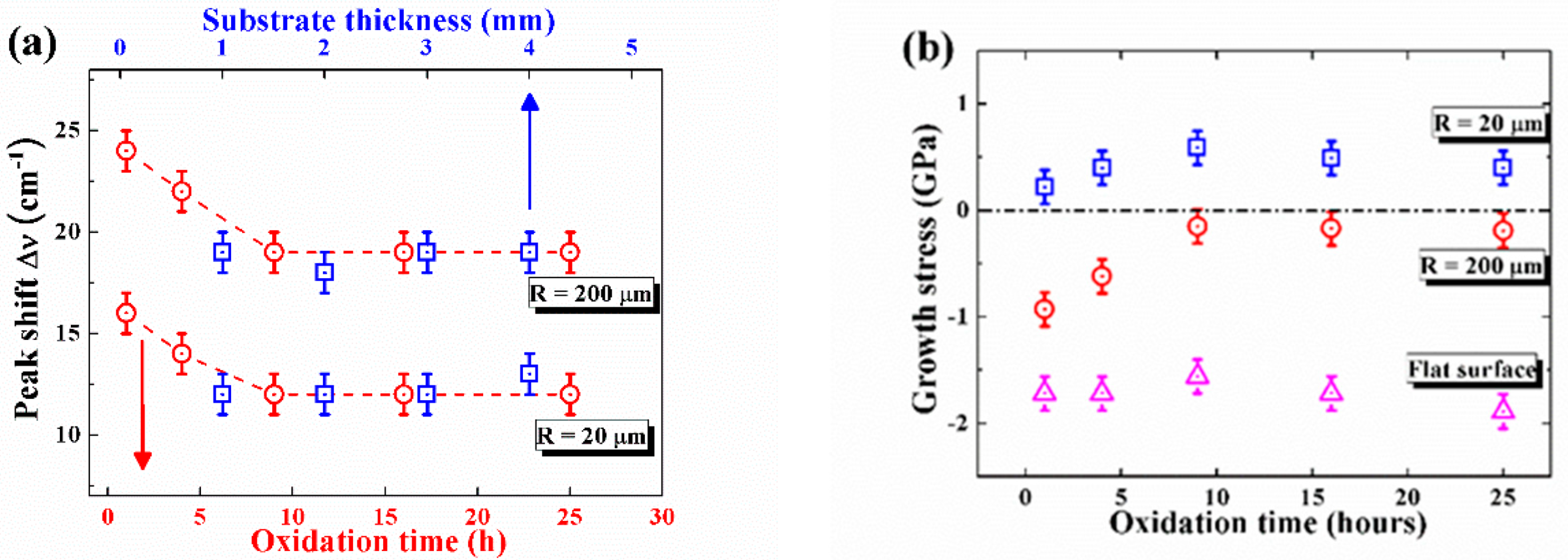
3. Results and Discussion
4. Conclusions
Author Contributions
Funding
Institutional Review Board Statement
Informed Consent Statement
Data Availability Statement
Conflicts of Interest
References
- Evans, A.G.; Mumm, D.R.; Hutchinson, J.W.; Meier, G.H.; Pettit, F.S. Mechanisms controlling the durability of thermal barrier coatings. Prog. Mater. Sci. 2001, 46, 505–553. [Google Scholar] [CrossRef]
- Clarke, D.R.; Levi, C.G. Materials design for the next generation thermal barrier coatings. Annu. Rev. Mater. Res. 2003, 33, 383–417. [Google Scholar] [CrossRef]
- Clarke, D.R.; Christensen, R.J.; Tolpygo, V. The evolution of oxidation stresses in zirconia thermal barrier coated superalloy leading to spalling failure. Surf. Coat. Technol. 1997, 94, 89–93. [Google Scholar] [CrossRef]
- Teixeira, V.; Andritschky, M.; Fischer, W.; Buchkremer, H.P.; Stover, D. Effects of deposition temperature and thermal cycling on residual stress state in zirconia-based thermal barrier coatings. Surf. Coat. Technol. 1999, 120, 103–111. [Google Scholar] [CrossRef]
- Sohn, Y.H.; Kim, J.H.; Jordan, E.H.; Gell, M. Thermal cycling of EB-PVD/MCrAlY thermal barrier coatings: I. Microstructural development and spallation mechanisms. Surf. Coat. Technol. 2001, 146, 70–78. [Google Scholar] [CrossRef]
- Jiang, P.; Yang, L.; Sun, Y.; Li, D.; Wang, T. Nondestructive measurements of residual stress in air plasma-sprayed thermal barrier coatings. J. Am. Ceram. Soc. 2020, 1–10. [Google Scholar] [CrossRef]
- Jiang, P.; Fan, X.; Sun, Y.; Wang, H.; Su, L.; Wang, T. Thermal-cycle dependent residual stress within the crack-susceptible zone in thermal barrier coating system. J. Am. Ceram. Soc. 2018, 101, 4256–4261. [Google Scholar] [CrossRef]
- Jiang, J.; Ma, X.; Wang, B. Stress analysis of the thermal barrier coating system near a cooling hole considering the free-edge effect. Ceram. Int. 2020, 46, 331–342. [Google Scholar] [CrossRef]
- Tolpygo, V.K.; Clarke, D.R. Wrinkling of α-alumina films grown by thermal oxidation—I. Quantitative studies on single crystals of Fe–Cr–Al alloy. Acta Mater. 1998, 46, 5153–5166. [Google Scholar] [CrossRef]
- Ranjbar-Far, M.; Absi, J.; Mariaux, G.; Dubois, F. Simulation of the effect of material properties and interface roughness on the stress distribution in thermal barrier coatings using finite element method. Mater. Des. 2010, 31, 772–781. [Google Scholar] [CrossRef]
- Ranjbar-Far, M.; Absi, J.; Mariaux, G. Finite element modeling of the different failure mechanisms of a plasma sprayed thermal barrier coatings system. J. Therm. Spray Technol. 2012, 21, 1234–1244. [Google Scholar] [CrossRef]
- Chen, Z.; Huang, H.; Zhao, K.; Jia, W.; Fang, L. Influence of inhomogeneous thermally grown oxide thickness on residual stress distribution in thermal barrier coating system. Ceram. Int. 2018, 44, 16937–16946. [Google Scholar] [CrossRef]
- Che, C.; Wu, G.Q.; Qi, H.Y.; Huang, Z.; Yang, X.G. Uneven growth of thermally grown oxide and stress distribution in plasma-sprayed thermal barrier coatings. Surf. Coat. Technol. 2009, 203, 3088–3091. [Google Scholar] [CrossRef]
- Song, J.; Qi, H.; Shi, D.; Yang, X.; Li, S. Effect of non-uniform growth of TGO layer on cracking behaviors in thermal barrier coatings: A numerical study. Surf. Coat. Technol. 2019, 370, 113–124. [Google Scholar] [CrossRef]
- He, M.Y.; Evans, A.G.; Hutchinson, J.W. The ratcheting of compressed thermally grown thin films on ductile substrates. Acta Mater. 2000, 48, 2593–2601. [Google Scholar] [CrossRef]
- Sun, Y.; Zhang, W.; Li, J.; Wang, T. Local stress around cap-like portions of anisotropically and nonuniformly grown oxide layer in thermal barrier coating system. J. Mater. Sci. 2013, 48, 5962–5982. [Google Scholar] [CrossRef]
- Sun, Y.; Li, J.; Zhang, W.; Wang, T. Local stress evolution in thermal barrier coating system during isothermal growth of irregular oxide layer. Surf. Coat. Technol. 2013, 216, 237–250. [Google Scholar] [CrossRef]
- Zhang, W.; Sun, Y.; Wang, T. Effect of spinel growth on the delamination of thermal barrier coatings. Key Eng. Mater. 2011, 462, 389–394. [Google Scholar] [CrossRef]
- Suresh, S.; Giannakopoulos, A.E. A new method for estimating residual stresses by instrumented sharp indentation. Acta Mater. 1998, 46, 5755–5767. [Google Scholar] [CrossRef]
- Zhao, X.; Xiao, P. Residual stresses in thermal barrier coatings measured by photoluminescence piezospectroscopy and indentation technique. Surf. Coat. Technol. 2006, 201, 1124–1131. [Google Scholar] [CrossRef]
- Gelfi, M.; Bontempi, E.; Roberti, R.; Armelao, L.; Depero, L.E. Residual stress analysis of thin films and coatings through XRD experiments. Thin Solid Films. 2004, 450, 143–147. [Google Scholar] [CrossRef]
- Tanaka, M.; Hasegawa, M.; Dericioglu, A.F.; Kagawa, Y. Measurement of residual stress in air plasma-sprayed Y2O3–ZrO2 thermal barrier coating system using micro-Raman spectroscopy. Mat. Sci. Eng. A. 2006, 419, 262–268. [Google Scholar] [CrossRef]
- Wu, R.T.; Wu, L.T. A powerful tool tomeasure residual stress in thermal barrier coatings: With the photoluminescence piezo-spectroscopy method, spallation life can be analytically predicted. IEEE Nanotechnol. Mag. 2017, 11, 20–23. [Google Scholar] [CrossRef]
- Manero, A., II.; Selimov, A.; Fouliard, Q.; Knipe, K.; Wischek, J.; Meid, C.; Karlsson, A.M.; Bartsch, M.; Raghavan, S. Piezospectroscopic evaluation and damage identification for thermal barrier coatings subjected to simulated engine environments. Surf. Coat. Technol. 2017, 323, 30–38. [Google Scholar] [CrossRef]
- Lipkin, D.M.; Clarke, D.R. Measurement of the stress in oxide scales formed by oxidation of alumina-forming alloys. Oxid. Met. 1996, 45, 267–280. [Google Scholar] [CrossRef]
- He, J.; Clarke, D.R. Determination of the piezospectroscopic coefficients for chromium-doped sapphire. J. Am. Ceram. Soc. 1995, 78, 1347–1353. [Google Scholar] [CrossRef]
- Gong, X.Y.; Clarke, D.R. On the measurement of strain in coatings formed on a wrinkled elastic substrate. Oxid. Met. 1998, 50, 355–376. [Google Scholar] [CrossRef]
- Munro, M. Evaluated material properties for a sintered alpha-alumina. J. Am. Ceram. Soc. 1997, 80, 1919–1928. [Google Scholar] [CrossRef]


| Conditions | h (µm) | l (µm) | R (µm) |
|---|---|---|---|
| Before oxidation | 10 ± 2 | 126 ± 3 | 203 ± 4 |
| After oxidation | 13 ± 3 | 120 ± 6 | 145 ± 7 |
Publisher’s Note: MDPI stays neutral with regard to jurisdictional claims in published maps and institutional affiliations. |
© 2021 by the authors. Licensee MDPI, Basel, Switzerland. This article is an open access article distributed under the terms and conditions of the Creative Commons Attribution (CC BY) license (https://creativecommons.org/licenses/by/4.0/).
Share and Cite
Zhao, Y.; Sun, F.; Jiang, P.; Sun, Y. Effects of Roughness on Stresses in an Oxide Scale Formed on a Superalloy Substrate. Coatings 2021, 11, 479. https://doi.org/10.3390/coatings11040479
Zhao Y, Sun F, Jiang P, Sun Y. Effects of Roughness on Stresses in an Oxide Scale Formed on a Superalloy Substrate. Coatings. 2021; 11(4):479. https://doi.org/10.3390/coatings11040479
Chicago/Turabian StyleZhao, Yang, Fan Sun, Peng Jiang, and Yongle Sun. 2021. "Effects of Roughness on Stresses in an Oxide Scale Formed on a Superalloy Substrate" Coatings 11, no. 4: 479. https://doi.org/10.3390/coatings11040479
APA StyleZhao, Y., Sun, F., Jiang, P., & Sun, Y. (2021). Effects of Roughness on Stresses in an Oxide Scale Formed on a Superalloy Substrate. Coatings, 11(4), 479. https://doi.org/10.3390/coatings11040479