Article

Effects of Different Post-Treatments on Arc Erosion Resistance of Cold-Sprayed AgC Composite Electric Contact

1
School of Power and Mechanical Engineering, Wuhan University, 8 South Donghu Road, Wuhan 430072, China
2
National Engineering Laboratory for Modern Materials Surface Engineering Technology, Guangdong Institute of New Materials, 363 Changxing Road, Guangzhou 510651, China
3
China Nuclear Power Technology Research Institute, 1001 Middle Shangbu Road, Shenzhen 518000, China
4
Suzhou Institute of Wuhan University, 188 Renai Road, Suzhou 215123, China
*
Author to whom correspondence should be addressed.
J.Y. Li and X. Zhou contributed equally to this work.
Coatings 2021, 11(3), 363; https://doi.org/10.3390/coatings11030363
Submission received: 19 February 2021 / Revised: 12 March 2021 / Accepted: 15 March 2021 / Published: 23 March 2021

Abstract

:
Graphite-silver (AgC) composite materials are widely used in outdoor high-voltage electrical switchgear due to their combining properties of excellent conductivity and outstanding arc-suppressing performance. However, the methods for fabricating AgC composite materials still have some limitations. In this study, the cold spray technique was adopted to deposit AgC composite coatings with the optimized parameters on the copper substrate. Then, AgC coatings were annealed in the furnace and treated by laser scanning, respectively, to further improve the arc erosion resistance performance of the coatings. The results show that the phase structure and electrical resistance of AgC coatings were not influenced by the post-treatment process. Furthermore, excellent hydrophobic performance was obtained after surface laser scanning treatment. The laser scanning treatment exhibited favorable advantages in enhancing the arc erosion resistance of AgC coatings, which indicated the lowest arc erosion rate compared with the cold-sprayed and annealed coatings.

1. Introduction

Silver-based composites have been widely used as electrical contact materials for several decades due to their outstanding electric properties [1,2]. Among them, AgC composites are most attractive because of their outstanding electrical conductivity, low contact resistance, good resistance to fusion welding, and excellent lubrication performance [3,4,5].
Many approaches have been proposed to fabricate AgC composites. The most widely used technology for the production of contact materials is powder metallurgy. However, the sintering bulk AgC composite with the silver as matrix would consume a lot of silver, inducing high cost in an industrial scale [5,6]. Compared with powder metallurgy, the electroplating process can largely reduce the consumption of silver by using the AgC composite as coating instead of bulk. In addition, the homogenous composition and uniformity of thickness of the process also promote the comprehensive electrical properties. However, the highly toxic cyanides in the solution could have great potential harm for the health of operators and the environment [7,8]. Other methods, such chemical co-deposition and sol-gel combined with chemical coating, are also proposed for synthesizing AgC composites for electrical contact application, but they suffer from the drawbacks of complex process and high cost. Therefore, a new fabricating technique that is eco-friendly, low-cost and highly efficient for high performance AgC contact is still highly desirable.
Cold spray was originally developed as an environmental coating technique for solid material deposition in the 1980s [9]. During this process, powder materials impact the substrate at an ultra-high speed and form a homogenous coating by plastic deformation. The whole process is conducted at near room temperature, thus it can fabricate versatile elements or alloy coatings with negligible oxidation [10,11]. Furthermore, due to the high speed of the powders, the coating presents uniform components and strong adhesion with substrates [12,13]. However, coatings deposited by cold spray may have some defects induced by severe plastic deformation, which will harm the electrical properties. Generally, post-treatments such as annealing are effective and economical ways to improve the electric performance of high-defect materials [14,15]. Furthermore, as a new surface modification technology, laser scanning shows the effects of both annealing and arraying the surface morphologies, which could possibly be used to improve the electric performance of the cold-spray coatings [16,17,18].
In this paper, AgC coatings were deposited by cold spray on copper substrates, and then subjected to thermal annealing and laser scanning treatments. Then, the phase and surface structures and arc erosion-resistance of the pre- and post-treatment samples were carefully investigated. The results showed that the laser scanning treatment could improve the arc erosion-resistance of the cold-spray coating, while thermal annealing was harmful for the erosion-resistance performance. The obtained results in this research may provide a possible approach with eco-friendly and large-scale capability to fabricate arc erosion resistant AgC composite coatings for application in electric switching contact.

2. Experimental Details

2.1. Materials

The average particle size of Ag powders (Guangdong New Materials Research Institute, Guangzhou, China) used in the cold spray was 10–50 μm, and the purity was 99.99%. Pure graphite powders (Jiangsu KYGP Co., Ltd., Suzhou, China) with a particle size of 10–50 μm were prepared by the chemical precipitation technique. The size of powders had been optimized and proved to be a proper dimension for the cold-spray process [19].

2.2. Coating Preparation

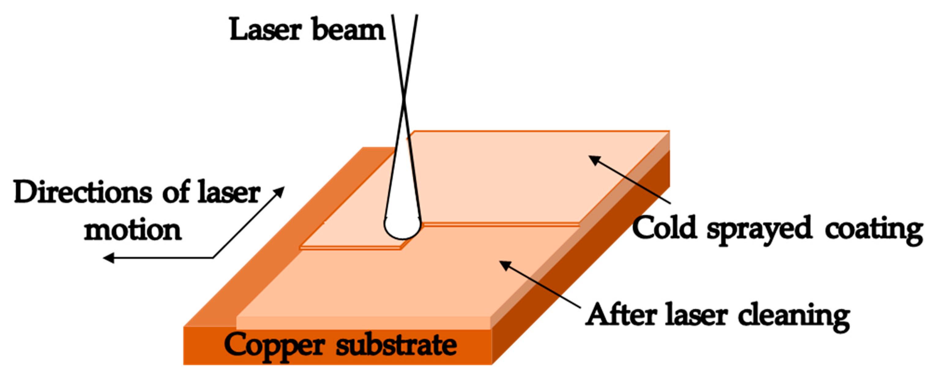
Before the deposition, the silver (97 wt.%) and graphite (3 wt.%) powders were mixed for 50 min in a stirrer. The morphology of mixed Ag (white particle) and C (black particle) powders after stirring is shown in Figure 1. The copper substrates (Φ = 100 mm with thickness of 5 mm) were cleaned with ethanol for fifteen minutes and dried in nitrogen. Then, the AgC composite coatings were fabricated onto the copper by the cold spray system (Plasma Giken PCS-1000, Guangzhou, China) under the optimized spraying parameters with a working pressure of 5 MPa and a spray distance of 30 mm. The thickness of the coatings obtained in this process is about 60 μm. Small size samples were cut from the large sample for different characterizations and treatments. The cut samples were ultrasonically cleaned with acetone followed by ethanol to remove the contaminant. Then, some samples were annealed in a furnace (XMT-8000, Wuhan, China) at the temperature of 400 °C for different durations (0.5–2 h). Laser scanning was conducted to treat the other samples at different speeds (to achieve different input power density) varied from 2000 mm/min to 6000 mm/min by a laser machine (HST-200, Wuhan, China), which was operated at a power of 120 W, 3000 ns pulse width and 50 kHz frequency. The full coverage pattern (line-by-line) of scanning was adopted in this part, as shown in Figure 2.

2.3. Material Characterizations

The surface and cross-section microstructures of the coatings were investigated by MIRA 3 filed-emission scanning electron microscopy (TESCAN Brno, Ltd., Oxford, UK) operated at voltage of 10 kV. The phase structure of coatings before and after annealing and laser scanning treatment was characterized by an XRD diffractometer with Cu radiation from XPert Pro (Wuhan, China). The resistivity of the samples was measured by a four-probe measurement system (HRMS-8000, Wuhan, China) with a measurement accuracy of ±0.5% at room temperature. The mean value of the contact angle was performed by a contact angle testing machine (OCA25 Drop Shape Analysis, Wuhan, China).

2.4. Arc Erosion Rate Test

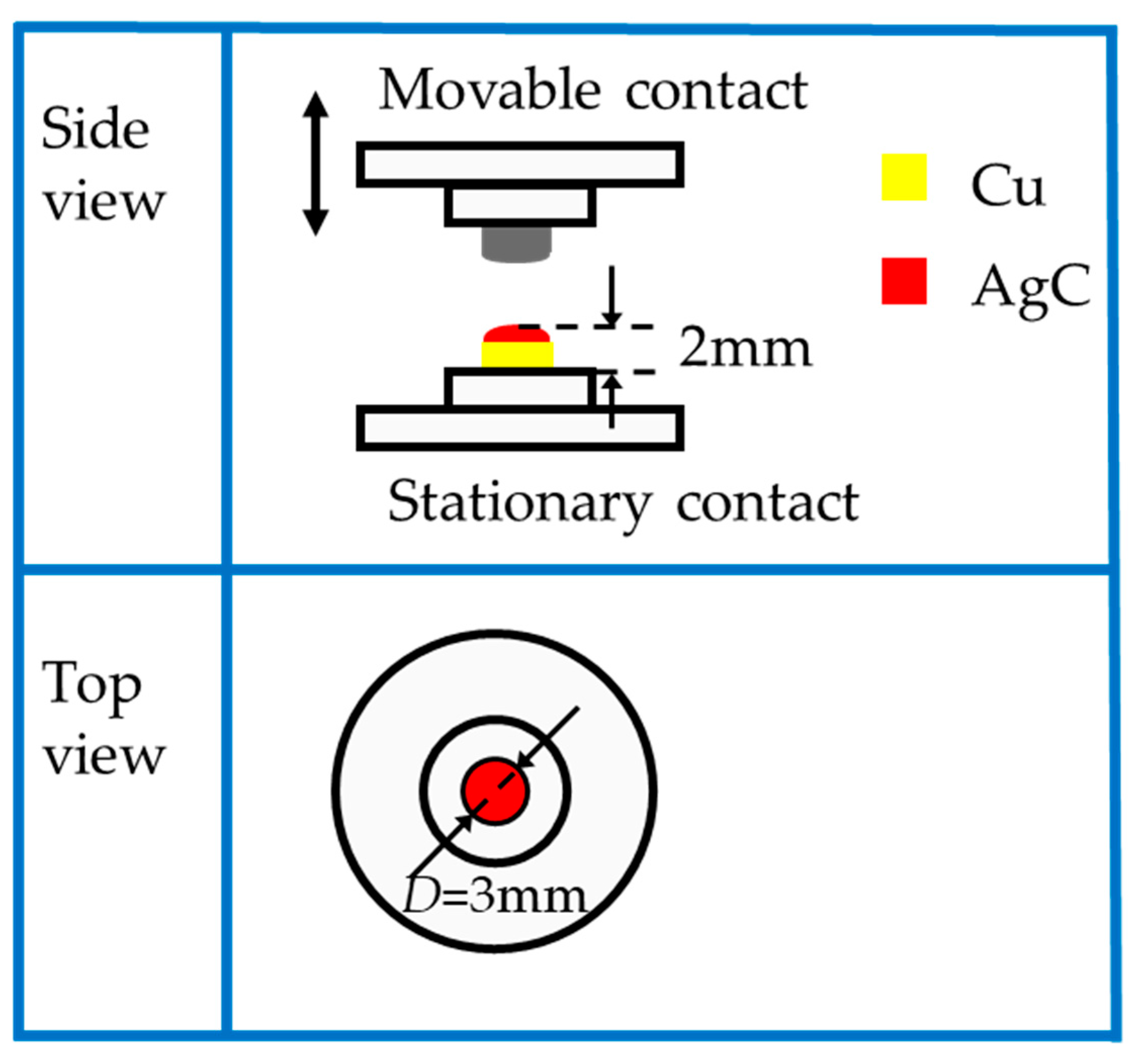
The arc erosion tests were carried out on the JF04C electric contact testing system, and the detailed schematic diagram and experimental parameters are demonstrated in Figure 3 and Table 1, respectively. Three kinds of samples including as-deposited AgC (D-AgC), annealed AgC (400 °C, 2 h) (A-AgC) and laser scanning AgC (4000 mm/min) (L-AgC) were tested with the same operation times. We used AgSnO2 electric contact as the cathode. The weight of each sample was measured after every 2000 operation times by an electrical scale (MS205DU, METTLER TOLEDO, Wuhan, China), the accuracy of which is 0.1 mg.

3. Results and Discussion

3.1. Effects of Post-Treatments on Phase Structure

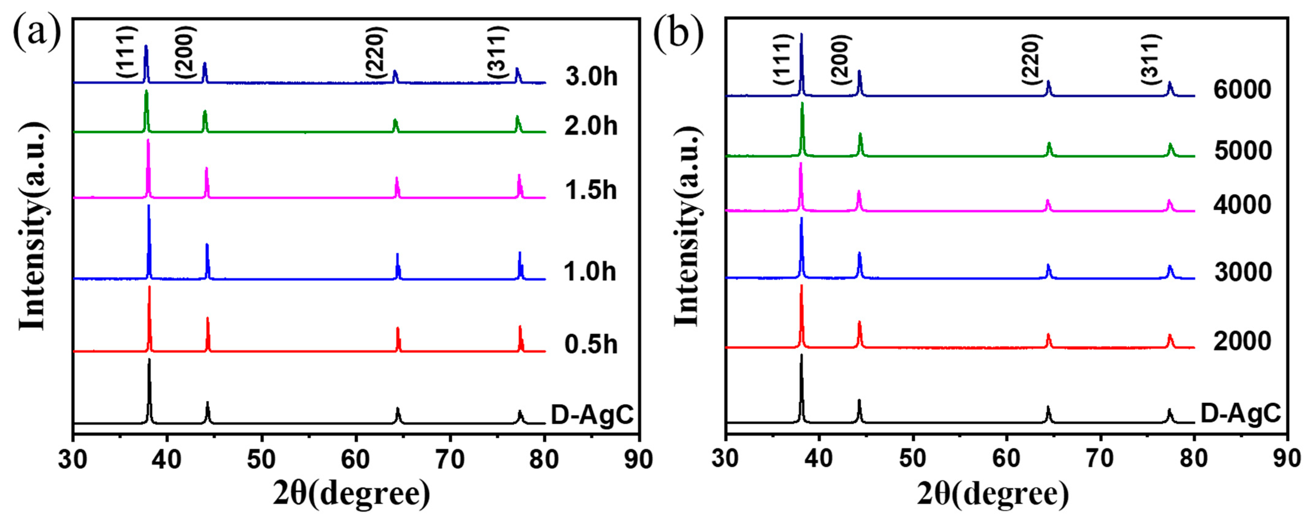
Figure 4 shows the XRD patterns of AgC coatings before and after treatments. As shown in Figure 4a, only four diffraction peaks corresponding to the silver-3C phase were observed for the D-AgC coating, indicating that no obvious oxidation happened during the deposition process. Additionally, no diffraction peak from the graphite was found, which might be due to the low content. After the annealing treatments, no obvious phase variations could be observed in the samples. However, a slight shift of the diffraction peaks to smaller angles about 0.5° could be detected for the samples after annealing for 2 h and 3 h. This may be attributed to the releasing of the compressive stress induced by the cold spray process [20]. Figure 4b shows the XRD graph of AgC coatings before and after the laser scanning with different scanning speeds, where no distinct changes were observed from these samples.

3.2. Effects of Post-Treatments on Morphologies and Wettability

Figure 5 shows the surface and cross-sectional morphologies of the as-deposited and post-treated AgC coatings. It was obvious that the Ag particles had experienced large plastic deformation resulting from high-speed collision with the substrate and formed irregular island-like shapes (Figure 5a). After surface laser treatment with a scanning speed of 4000 mm/min, a rough surface morphology with complex structures and particles (Figure 5b) was observed due to the melting caused by the pulsed laser [18,21]. As shown in Figure 5c, the surface of the coating after annealing for 2 h at 400 °C exhibited a relatively smooth and flat surface since the recrystallization of Ag grains [15].
The roughness is also used to characterize the effects of post-treatments on surface morphologies. The D-AgC sample had a roughness of 7.875 μm. After laser scanning, the roughness increased to 8.030 μm. However, the annealing can slightly reduce the surface roughness to 7.265 μm. These distinct morphology differences could have an effect on surface wettability, which is a property important for outdoor contact applications. As shown in the inserted images in Figure 5a,b, the L-AgC sample exhibited a slightly higher contact angle of 125.5° than the D-AgC sample with a value of 123.2°, which might be caused by the more complex structure inducing higher roughness. For the A-AgC sample, its contact angle decreased to a low value of 65.9° due to the lower roughness after annealing. Since the as-deposited and the laser scanned samples both exhibited good hydrophobicity, they would present a poor adsorption of water outdoors, which will be beneficial for the long-term service of electrical contact.
The good combination between interfaces is also crucial for an electric contact material to be used long term. Figure 5ai shows that a serrated interface between the AgC coating and copper substrate existed, and no lamination or crack could be observed, which meant that a good adhesion was obtained by the cold spray technique. Since the laser scanning process is a superficial layer modification technology, there was no obvious change in the interface (Figure 5bi). Furthermore, the AgC coating also exhibited an excellent structure stability, even though it experienced the annealing process at 400 °C for 2 h (Figure 5ci).

3.3. Effects of Post-Treatments on Arc Erosion Resistance

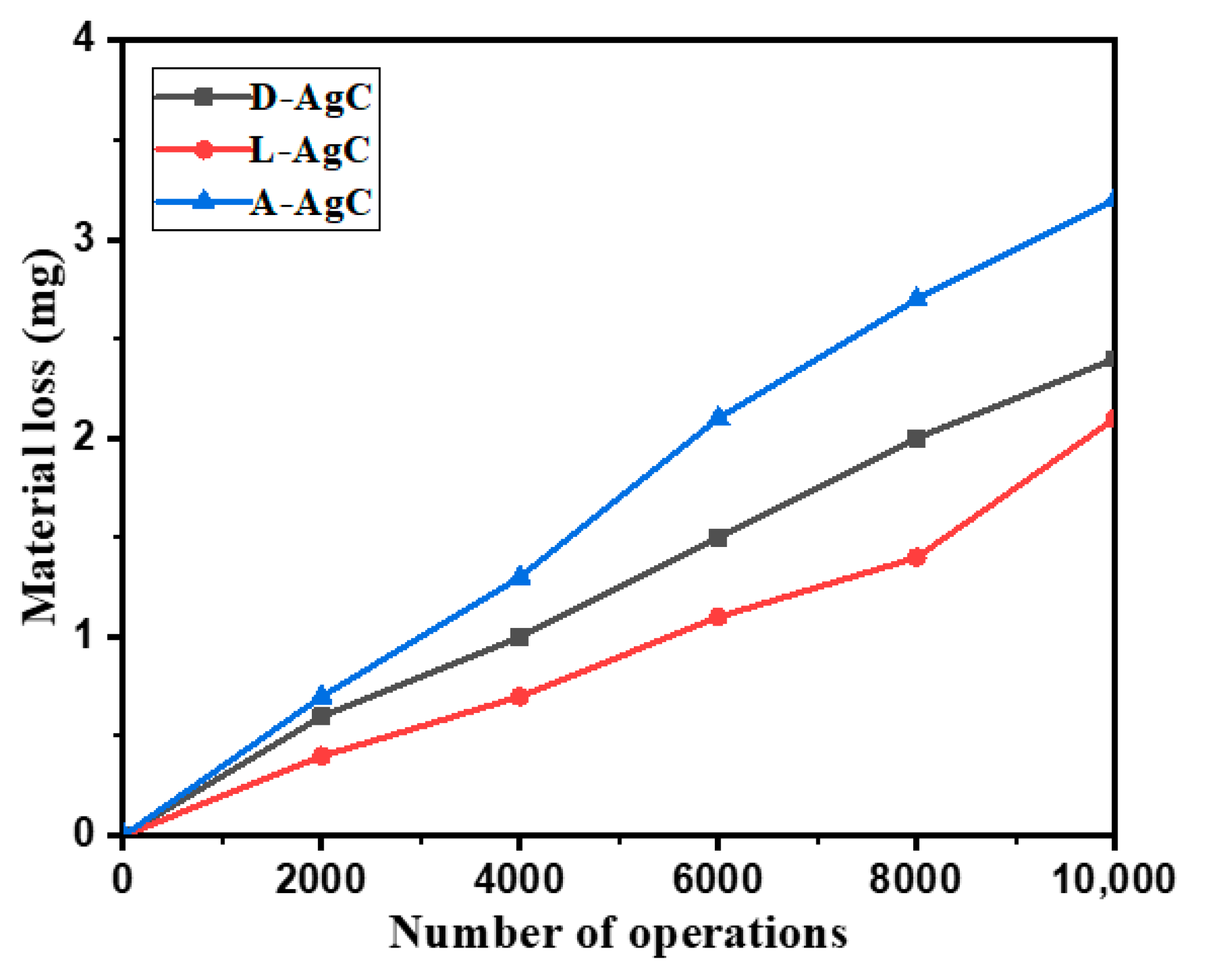
The arc erosion rate is a primary standard for the erosion resistance of an electric contact material, which can be characterized by mass loss during the arc erosion process [22]. First, we measured the electrical resistance of the three samples before and after treatments. The results showed that post-treatments had negligible effects on the electrical resistance, as the resistance of these samples was about 2.6 × 10⁻⁶ Ω·cm, which can meet the demands of electric switching contact. Figure 6 shows the mass loss of D-AgC, A-AgC and L-AgC electric contacts after 10,000 arc erosion cycles. The laser-treated sample always showed the lowest erosion mass loss compared with the as-deposited and annealed samples with switching operation times up to 10,000 cycles. Furthermore, the mass loss of the annealed sample was significantly higher than that of the as-deposited AgC sample. As a consequence, the laser-scanned AgC coating exhibited a favorable arc erosion resistance.
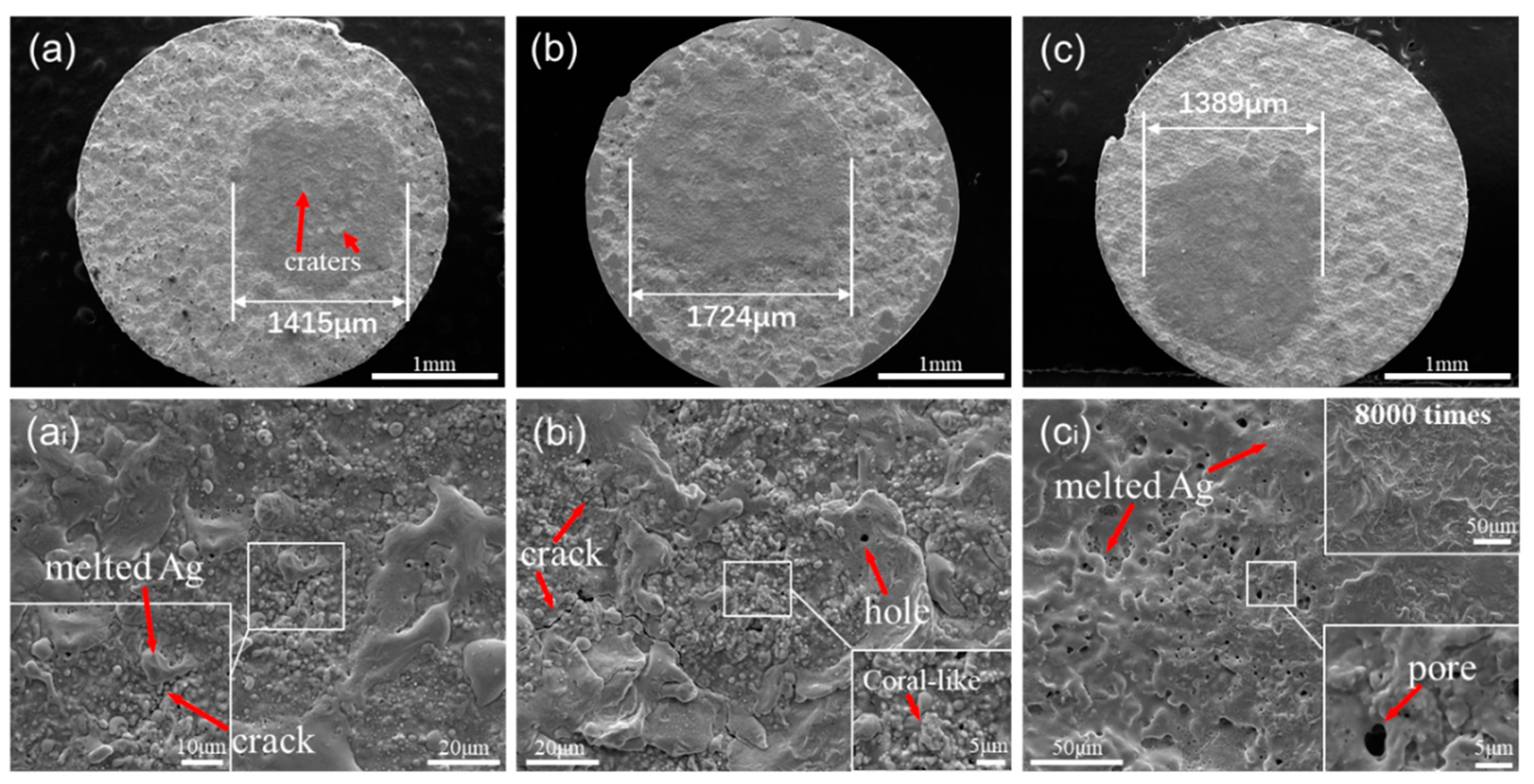
Surface morphologies of the three samples were also observed to reveal the mechanisms of different erosion rates behind. Figure 7 demonstrates the morphologies of the eroded surface for as-deposited AgC, annealed AgC and laser-scanned AgC electric contact after 10,000 switching operations. As shown in the low-magnification images in Figure 7a–c, the dark and bright areas are the eroded and non-eroded zones by the arc, respectively. Compared with the as-deposited AgC coating, the annealed coating exhibited a much larger erosion area with a diameter of 1724 μm, while the laser-scanned AgC coatings had a slightly smaller area with a diameter of 1389 μm. Even though the laser-scanned sample had a closer erosion diameter to the as-deposited sample of 1415 μm, the deeper crater-like pits on the surface of the as-deposited AgC coating signed by the red arrows meant more serious arc erosion.
To reveal the specific erosion behaviors of the coatings clearly, magnified images of the erosion area for the as-deposited AgC, annealed AgC and laser-scanned AgC samples after 10,000 switching operations are presented in Figure 7ai–ci. As shown in Figure 7ai for the as-deposited AgC coating, common morphologies caused by arc erosion such as island-like melted silver, evident spherical silver, some pores and small cracks can be clearly observed [23,24]. The annealed sample exhibited a similar erosion morphology with the as-deposited sample. However, more and longer cracks were observed on the annealed sample, which could be responsible for the higher erosion rate. In addition, the coral-like structures on the annealed sample also indicated a more serious erosion.
It was worth noticing that the erosion micromorphology of laser-scanned AgC was quite different from that of the other two samples (Figure 7ci). It seemed that the surface of the coating became smoother and flatter after the erosion test. Except for the pores with different diameters and some melt and flow traces, no other arc erosion characteristics could be observed on the eroded surface. These different erosion behaviors would explain the lowest arc erosion rate of the laser-scanned sample. In addition, when the erosion cycle was lower than 8000 times (shown in Figure 7ci), no obvious pores could be observed. However, the special morphology resulting from laser scanning disappeared after 8000 arc erosion cycles. When the erosion cycle increased to 10,000, mass pores appeared obviously on the eroded surface. These observations could be responsible for the higher erosion rate after 8000 operation times in Figure 6 for the laser-scanned sample.
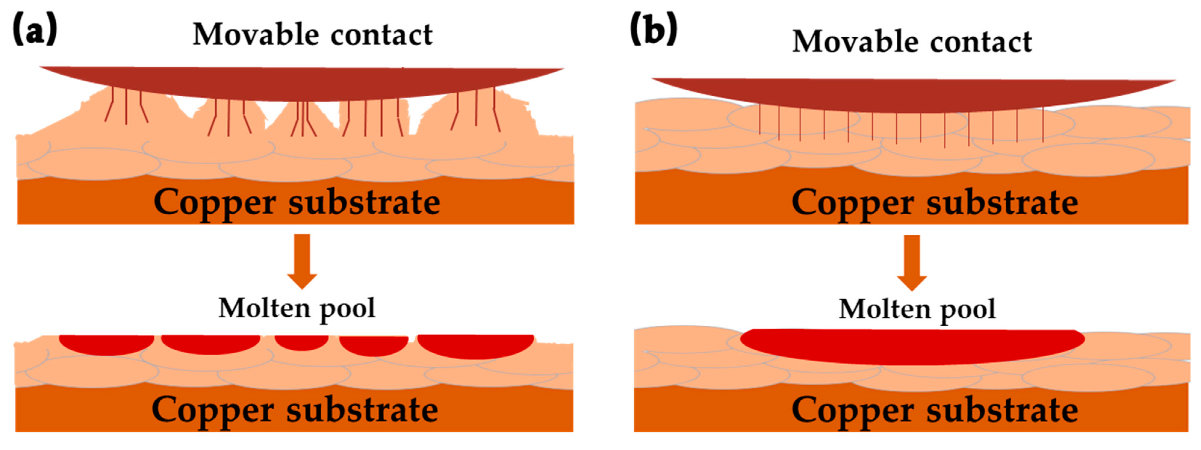
The discussion about the reason for the different arc erosion rates of these three kinds of AgC coatings is given below. There are many reasons leading to this result, which can be roughly concluded into two categories according to its characters. One is the different stress states, as original compressive stress can prevent the structure from loosening [25,26], which will reduce the erosion. The other category is the different surface morphologies that can change the character of the connection between the stationary and movable contacts [27,28]. Figure 8 shows the schematic image of the erosion process influenced by surface morphology. It meant that the electric current would be dispersed [29] when there were many micro-nano structures on the surface (Figure 8a), which would lead to the formation of many small and dispersive molten pools. In this condition, the evaporation and sputtering would reduce. On the contrary, the surface without micro-nano structures (shown in Figure 8b) would generate the larger concentrated molten pool during the erosion test, which would increase the evaporation and sputtering resulting in increased mass loss [30]. From the discussion, it could be concluded that the releasing of compressive stress and the surface without a special structure caused a worse erosion resistance than the as-deposited sample. Furthermore, the surface with the micro-nano structure might be the main reason that the erosion resistance of the sample was enhanced after laser scanning. However, the eroded mechanism of cold-sprayed and post-treated AgC coatings is complex and more studies are worthy to perform in the future.

4. Conclusions

The surface morphologies, wettability, microstructure and arc erosion properties of cold-sprayed AgC composite coatings with and without post-treatment were investigated in this paper. The results showed that AgC coating by the cold spraying process exhibited excellent adhesion and outstanding electric properties. As-deposited and laser scanning treated AgC coatings demonstrated high hydrophobicity with contact angles over 120°, which showed favorable application potential for outdoor contact materials. By comparing the surface topography and the mass loss of coatings after 10,000 times of arc erosion, it was shown that the laser scanning treated AgC coating possesses the best arc erosion resistance and the lowest arc erosion rate. The present results imply that AgC composites can be fabricated by the environmentally-friendly cold spray technique, and laser scanning treatment can be adopted to enhance the arc erosion resistance of the coating for industrial application in electrical contact switchgear devices.

Author Contributions

Conceptualization, B.Y.; methodology, X.Z.; formal analysis, J.L. and X.Z.; investigation, Y.L. and Z.L.; resources, Y.C., R.H. and J.T.; data curation, J.L. and X.Z.; writing—original draft preparation, J.L.; writing—review and editing, J.L., X.Z. and B.Y.; project administration, B.Y.; funding acquisition, B.Y. and J.Z. All authors have read and agreed to the published version of the manuscript.

Funding

This project was supported by the National Key R&D Program of China (Grant No. 2018YFB1106100), the Science and Technology Program Project of Shenzhen (Zhong 2019N032), the National Natural Science Foundation of China (U1832127), the Natural Science Foundation of Jiangsu Province (BK20171233) and the Guangdong Academy of Sciences’ Project of Constructing First-class Domestic Research Institutions (No. 2020GDASYL-20200302011).

Institutional Review Board Statement

Not Applicable.

Informed Consent Statement

Not Applicable.

Data Availability Statement

Data Sharing is not applicable for this article.

Conflicts of Interest

The authors declare no conflict of interest.

References

  1. Jaćimović, J.; Felberbaum, L.; Giannini, E.; Teyssier, J. Electro-mechanical properties of composite materials for high-current contact applications. J. Phys. D Appl. Phys. 2014, 47. [Google Scholar] [CrossRef]
  2. Ding, J.; Sun, Z.; Zhang, P.; Tian, W.; Zhang, Y. Current Research Status and Outlook of Ag-based Contact Materials. Mater. Rev. 2018, 32, 58–66. [Google Scholar] [CrossRef]
  3. Mutzel, T.; Kempf, B. Silver tungsten carbide contacts fork circuit breaker applications. Electr. Contacts Proc. Annu. Holm Conf. Electr. Contacts 2015. [Google Scholar] [CrossRef]
  4. Borkowski, P.; Walczuk, E.; Wojcik-Grzybek, D.; Frydman, K.; Zasada, D. Electrical properties of Ag-C contact materials containing different allotropes of carbon. Electr. Contacts Proc. Annu. Holm Conf. Electr. Contacts 2010, 167–175. [Google Scholar] [CrossRef]
  5. Rehani, B.R.; Joshi, P.B.; Kaushik, V.K. Nanostructured silver-graphite electrical contact materials processed by mechanical milling. Indian J. Eng. Mater. Sci. 2009, 16, 281–287. [Google Scholar]
  6. Rehani, B.; Joshi, P.B.; Khanna, P.K. Fabrication of silver-graphite contact materials using silver nanopowders. J. Mater. Eng. Perform. 2010, 19, 64–69. [Google Scholar] [CrossRef]
  7. Liu, A.; Ren, X.; Zhang, J.; Li, D.; An, M. Complexing agent study for environmentally friendly silver electrodeposition (II): Electrochemical behavior of silver complex. RSC Adv. 2016, 6, 7348–7355. [Google Scholar] [CrossRef]
  8. Bomparola, R.; Caporali, S.; Lavacchi, A.; Bardi, U. Silver electrodeposition from air and water-stable ionic liquid: An environmentally friendly alternative to cyanide baths. Surf. Coat. Technol. 2007, 201, 9485–9490. [Google Scholar] [CrossRef]
  9. Srikanth, A.; Bolleddu, V. A review on characteristics of cold sprayed coatings. Aust. J. Mech. Eng. 2020, 1–17. [Google Scholar] [CrossRef]
  10. Singh, S.; Singh, H.; Buddu, R.K. Microstructural investigations on bonding mechanisms of cold-sprayed copper with SS316L steel. Surf. Eng. 2020, 36, 1067–1080. [Google Scholar] [CrossRef]
  11. Li, J.; Zhang, Y.; Ma, K.; Pan, X.-D.; Li, C.-X.; Yang, G.-J.; Li, C.-J. Microstructure and Transparent Super-Hydrophobic Performance of Vacuum Cold-Sprayed Al2O3 and SiO2 Aerogel Composite Coating. J. Therm. Spray Technol. 2018, 27, 471–482. [Google Scholar] [CrossRef]
  12. Huang, C.; Li, W.; Xie, Y.; Planche, M.P.; Liao, H.; Montavon, G. Effect of Substrate Type on Deposition Behavior and Wear Performance of Ni-Coated Graphite/Al Composite Coatings Deposited by Cold Spraying. J. Mater. Sci. Technol. 2017, 33, 338–346. [Google Scholar] [CrossRef]
  13. Li, W.; Assadi, H.; Gaertner, F.; Yin, S. A Review of Advanced Composite and Nanostructured Coatings by Solid-State Cold Spraying Process. Crit. Rev. Solid State Mater. Sci. 2019, 44, 109–156. [Google Scholar] [CrossRef] [Green Version]
  14. Chavan, N.M.; Ramakrishna, M.; Phani, P.S.; Rao, D.S.; Sundararajan, G. The influence of process parameters and heat treatment on the properties of cold sprayed silver coatings. Surf. Coat. Technol. 2011, 205, 4798–4807. [Google Scholar] [CrossRef]
  15. Wang, J.; Wang, C.; Kang, Y. The effects of annealing treatment on microstructure and contact resistance properties of cold sprayed Ag-SnO2 coating. J. Alloy. Compd. 2017, 714, 698–703. [Google Scholar] [CrossRef]
  16. Xiong, W.; Hao, L.; Li, Y.; Tang, D.; Cui, Q.; Feng, Z.; Yan, C. Effect of selective laser melting parameters on morphology, microstructure, densification and mechanical properties of supersaturated silver alloy. Mater. Des. 2019, 170, 107697. [Google Scholar] [CrossRef]
  17. Major, B.; Ciach, R.; Ebner, R.; Jeglitsch, F.; Kriszt, B.; Rabitsch, K. Laser microstructure modification of aluminium alloys and steels. Phys. Status Solidi 1994, 141, 15–30. [Google Scholar] [CrossRef]
  18. Won, S.J.; Kim, H.S. Effects of laser parameters on morphological change and surface properties of aluminum alloy in masked laser surface texturing. J. Manuf. Process. 2019, 48, 260–269. [Google Scholar] [CrossRef]
  19. Xie, J.; Cao, S.; Bai, X.; Li, G.; Yan, X.; Zheng, L. Preparation of electrical contact materials by cold gas-spray. Rare Met. Mater. Eng. 2014, 43, 2989–2992. [Google Scholar] [CrossRef]
  20. Ghelichi, R.; Guagliano, M. Coating by the Cold Spray Process: A state of the art. Frat. Integrità Strutt. 2009, 3, 30–44. [Google Scholar] [CrossRef] [Green Version]
  21. Raza, M.S.; Das, S.S.; Tudu, P.; Saha, P. Excimer laser cleaning of black sulphur encrustation from silver surface. Opt. Laser Technol. 2019, 113, 95–103. [Google Scholar] [CrossRef] [Green Version]
  22. Wu, Q.; Xu, G.; Yuan, M.; Wu, C. Influence of operation numbers on arc erosion of Ag/CuO electrical contact material. J. Mater. Sci. Mater. Electron. 2020, 31, 2497–2513. [Google Scholar] [CrossRef]
  23. Niu, L.; Liu, M. Studty of the Arc Erosion in Electromobile Contactor Electrode Consisting of Ag and C Composites. In Proceedings of the 2020 5th Asia Conference on Power and Electrical Engineering, ACPEE 2020, Chengdu, China, 4–7 June 2020; pp. 1923–1927. [Google Scholar]
  24. Wójcik-Grzybek, D.; Frydman, K.; Borkowski, P. The influence of the microstructure on the switching properties of Ag-C, Ag-WC-CAND Ag-W-C contact materials. Arch. Metall. Mater. 2013, 58, 1059–1065. [Google Scholar] [CrossRef] [Green Version]
  25. Peat, T.; Galloway, A.; Toumpis, A.; McNutt, P.; Iqbal, N. The erosion performance of cold spray deposited metal matrix composite coatings with subsequent friction stir processing. Appl. Surf. Sci. 2017, 396, 1635–1648. [Google Scholar] [CrossRef] [Green Version]
  26. Li, S.; Guo, X.; Zhang, S.; Feng, J.; Song, K.; Liang, S. Arc erosion behavior of TiB2/Cu composites with single-scale and dual-scale TiB2 particles. Nanotechnol. Rev. 2019, 8, 619–627. [Google Scholar] [CrossRef]
  27. Li, L.T.; Liang, X.M.; Xing, Y.Z.; Yan, D.; Wang, G.F. Measurement of real contact area for rough metal surfaces and the distinction of contribution from elasticity and plasticity. J. Tribol. 2021, 143, 071501. [Google Scholar] [CrossRef]
  28. Saputra, E.; Ismail, R.; Jamari, J.; Bayuseno, A.P. Analysis of the contact area of smooth and rough surfaces in contact with sphere indenter using finite element method. MATEC Web Conf. 2016, 58, 04007. [Google Scholar] [CrossRef] [Green Version]
  29. Wang, D.D.; Tian, W.B.; Ding, J.X.; Zhu, Y.F.; Zhang, P.G.; Zhang, Y.; He, W.; Sun, Z.M. The beauty and the deed of silver during arc erosion of Ag/Ti3AlC2 contacts. J. Alloy. Compd. 2020, 820. [Google Scholar] [CrossRef]
  30. Shea, J.J. High Current AC break Arc Contact Erosion. In Proceedings of the 54th IEEE Holm Conference on Electrical Contacts, Orlando, FL, USA, 27–29 October 2008. [Google Scholar] [CrossRef]
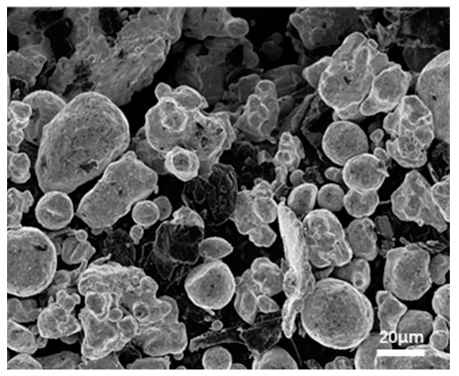
Figure 1. Morphology of the mixed Ag–C powders.
Coatings 11 00363 g001
Figure 2. Full coverage pattern scanning.
Coatings 11 00363 g002
Figure 3. Schematic diagram of arc erosion tests.
Coatings 11 00363 g003
Figure 4. XRD patterns of the AgC coatings after (a) different annealing durations and (b) different laser scanning speeds.
Coatings 11 00363 g004
Figure 5. The surface and cross-sectional morphologies of the as-deposited and treated AgC coatings: (a,ai) for D-AgC, (b,bi) for L-AgC, (c,ci) for A-AgC, and the insets show the contact angles of each sample, respectively.
Coatings 11 00363 g005
Figure 6. The mass changes of the D-AgC, A-AgC, and L-AgC samples with numbers of operations.
Coatings 11 00363 g006
Figure 7. The surface morphologies after 10,000 arc erosion cycles of the (a) D-AgC, (b) A-AgC and (c) L-AgC, as well as the corresponding extended images (ai,bi,ci) for the erosion area.
Coatings 11 00363 g007
Figure 8. The schematic diagrams of surface morphology dependent erosion process: (a) rough surface would induce smaller molten pools, and (b) smooth surface with larger molten pool.
Coatings 11 00363 g008
Table 1. Experimental parameters for arc erosion tests.
Contact MaterialAgC with Different Treatments
Circuit conditionDC18V, 10A, resistive load
Frequency1 Hz
Number of operations2000, 4000, 6000, 8000, 10,000
Switching modeDC (direct current) mode
Contact force0.8 N
Surrounding gasAir
Electrode spacing1.3 mm
Publisher’s Note: MDPI stays neutral with regard to jurisdictional claims in published maps and institutional affiliations.