Abstract
Thick Cu−Sn alloy layers were produced in an [EMIM]Cl ionic-liquid solution from CuCl2 and SnCl2 in different ratios. All work, including the electrodeposition, took place outside the glovebox with a continuous argon stream over the electrolyte at 95 °C. The layer composition and layer thickness can be adjusted by the variation of the metal-salts content in the electrolyte. A layer with a thickness of up to 15 µm and a copper content of up to ωCu = 0.86 was obtained. The phase composition was characterized by scanning electron microscopy (SEM), X-ray diffraction (XRD), and X-ray fluorescence (XRF). Furthermore, it was found that the relationship between the alloy composition and the concentration of the ions in the electrolyte is described as an irregular alloy system as according to Brenner. Brenner described such systems only for aqueous electrolytes containing complexing agents such as cyanide. In this work, it was confirmed that irregular alloy depositions also occur in [EMIM]Cl.
1. Introduction
While pure copper is relatively soft, bronze has high strength and hardness due to the alloy component tin. In addition, this system is highly resistant to corrosion (e.g., in seawater) and wear. The conductivity for electricity and heat is good with low tin contents, although not as high as that of pure copper. As the tin content increases, the conductivity decreases, while strength and hardness increase. It also offers good spring and sliding properties and has excellent fatigue strength. Thus, copper-tin layers could be used where the replacement of nickel is required. Nickel coatings are among the most frequently used galvanic coatings because of their good corrosion and wear properties, as well as their appealing appearance. Their disadvantage is their allergenicity. Since nickel layers release nickel over time, they are regulated by the REACH Regulation, Annex XVII, entry 27, which applies to the European union. Bronze coatings have a long history of being used as a replacement for nickel. In recent years, there has been much research on improving aqueous electrolytes [1]. However, hydrogen embrittlement remains a challenge for the deposition of such layers in these electrolytes. The standard potentials of the metal ions are approximately 0.5 V apart. If too high a current density is used, significant hydrogen development occurs, especially in acidic baths [2]. In addition, the solubility of the metal salts is severely limited, and the stability of the bath in air is a challenge. Without additives, it is difficult to maintain the composition of the bath due to the potential difference [3]. That is why the first copper-tin electrolytes employed the use of poisonous cyanides and later thio compounds [4]. Ionic liquids (ILs) offer a real alternative to aqueous electrolytes. They have become more and more popular in recent years. They have a much larger potential window without side reactions, and they can build up a coordination to metal ions, which leads to good solubility of many metal ions. In addition, they are mostly non-toxic and therefore do require no treatment of the bath waste. As opposed to many other organic solvents such as dichloromethane, they are electrochemically and temperature stable in addition to being less flammable [5,6]. For these reasons, many electrochemical properties of metals in ionic liquids have already been studied [7,8,9,10]. There have been experiments with Cu–Sn layers for deposition from ionic liquids. Murase and co-workers electrodeposited Cu–Sn alloys and discussed the formation mechanism of the intermetallic phases and their reduction potential [11,12]. Hsieh performed a deposition of Cu–Sn alloy in 1-ethyl-3-methylimidazolium dicyanamide ([EMIM-DCA]), showing that the formed nanobrush-shaped alloys have a phase composition of Cu3Sn and Sn [13]. Akira and Murase et al. coated non-conducting polymer structures with Cu-Sn layers. First, they coated the substrate chemically with copper in 1-ethyl-3-methylimidazolium bis(trifluoromethanesulfonyl)imide ([EMI-Tf2N]), and an electrochemical deposition in the same ionic liquid was subsequently carried out. They obtained a layer consisting of Cu6Sn5 and/or Cu3Sn phases. Unfortunately, they do not give any information about the thickness or the deposition rate [14,15]. Ghosh conducted investigations on the influence of the concentrations of the metal salts on one another in choline chlorides. They were able to achieve a deposition rate of up to (0.040 ± 0.004) µm/min on a steel substrate [16]. Jie et al. coated Cu–Sn alloys in 1-butyl-3-methylimidazolium chloride ([BMIM]Cl). The deposition took place during cyclic voltammetry and the crystallization mechanisms was studied with chronoamperometry [17]. These works illustrate an increasing interest in the development of a suitable ionic liquid electrolyte.
In general aqueous media, Brenner described the deposition of copper-tin alloys in cyanide baths as an irregular alloy system [3]. Such processes are characterized by the fact that diffusion phenomena and thus deposition conditions play a subordinate role during the deposition. Moreover, the individual potentials of the metal ions have a greater influence on the layer composition. This is most common for electrolytes in which the metal ions are complexly bound, which affects their potential, e.g., cyanide copper and zinc. The irregular type of deposition occurs mainly in metals whose static potential are close to one another. The nobler metal is deposited first. The proportion of the nobler component in the layer increases logarithmically with the proportion of the metal ions present in the electrolyte and asymptotically approaches a limit. To determine whether this behaviour is also correct for the system [EMIM]Cl ionic liquid, CuCl2 and SnCl2 are investigated in this study. [EMIM]Cl was chosen as a solvent based on previous promising results, such as in the deposition of Al-W alloys from [EMIM]Cl [18] and Ag-W alloys from [EMIM]Cl/AlCl3 [12]. In addition, it is important for the further development of ionic liquids as electrolytes to improve the deposition performance and better understand the interrelations between different bath parameters such as the metal-salt concentration and the obtained layer.
2. Materials and Methods
The electrolyte consists of Sn(II)-chloride (anhydrous) SnCl2 (99.9%, abcr GmbH, Germany), Cu(II)-chloride (anhydrous) CuCl2 (99.9%, abcr GmbH, Karlsruhe, Germany), and 1‑Ethyl-3-methylimidazolium chloride [EMIM]Cl (>98%, (Ionic Liquids Technologies GmbH, Heilbronn, Germany) ionic liquid (IL). The use of the ionic liquid outside the glove box necessitates a special approach. Water contact with the electrolyte must be avoided. Therefore, all flasks must be meticulously flushed with Ar. In addition, all tools must be dried. The substances are hygroscopic and/or release HCl on contact with atmospheric moisture. The preparation of 40 mL electrolyte took place in a round-bottom flask under Ar. Before the experiments were conducted, the IL was heated up to 95 °C and dried for 4 h under vacuum at 3 mbar. Afterwards, the flask was put back under the protective Ar atmosphere. Subsequently, the CuCl2 and the SnCl2 were added. It was then dried again for 4 h under vacuum (3 mbar) at 95 °C until the metal salts were completely dissolved and no more bubbles formed in the IL. For the galvanostatic deposition, the electrolyte was put into another Ar-purged flask. An industrial Zn-covered hull-cell steel plate with a defined surface of 10 × 10 mm2 was used as the cathode. The Zn layer was removed by HCl (6 M), and the hull-cell plate was subsequently cleansed with ethanol. The anode, which was a Sn pin (d = 6 mm), was positioned at a distance of approximately 40 mm from the cathode. The electrochemical deposition was carried out at 95 °C under constant stirring (100 rpm) with a magnetic stirring bar and Ar counterflow for 3 h. These conditions had to be chosen because the necessary viscosity of the ionic liquid required it. If lower stirring speeds or temperatures would have been selected, this would have resulted in the solidification of the electrolyte, impairing the deposition. The plating baths used to deposit the different alloy compositions contained different concentrations, as shown in Table 1, ranging from 0 to 0.29 M SnCl2 and 0.01 to 0.30 M CuCl2, so that the resultant electrolyte ratios were 0.03, 0.17, 0.50, 0.67, 0.83, or 1.00.

Table 1.
Electrolyte composition.
A potentiostat (Autolab PGSTAT204, Metrohm, Herisau, Switzerland) was used in the galvanostatic mode. The potential values for the different depositions were not measured. After the deposition, the cathode was removed from the electrolyte and rinsed first with ethanol, then water. To avoid possible contamination by side reactions during the process, every deposition was carried out in freshly prepared electrolyte. The deposit’s morphology and composition were determined with a scanning electron microscope (NEON40EsB, Zeiss, Oberkochen, Germany), which had an energy-dispersive X-ray spectroscopy (EDX) system and a secondary-electron (SE) detector with an excitation voltage of 25 kV, and with optical emission spectrometry (OES, Optima 8300, Perkin Elmer, Waltham, MA, USA). For X-ray diffraction (XRD, D8 Discover, Bruker AXS, Karlsruhe, Germany) a diffractometer with Co Kα radiation (tube parameters: point focus, 40 kV, 40 mA), polycap optics, a pinhole aperture with a diameter of 0.5 mm, and a 1D detector LYNXEYE XE with a step size of 0.02° and 17.8 s/step were used. The phase assignment was done using the PDF-2 2014 database. The potentiostat was also used for the measurement of cyclovoltammograms with a sweep rate of 0.01 V/s. A three-electrode array was used. The arrangement was chosen in the same way as in the practical deposition with the steel sheet to be coated as working electrode, the tin pin as counter electrode, and a platinum sheet (5 × 10 mm2) as reference electrode.
3. Results and Discussion
The coatings were deposited with different concentration ratios of CuCl2 and SnCl2, and the resulting effect on the coating was investigated. Figure 1 shows how the Cu content of the deposited layer changes with the ratio of Cu2+ ions to Sn2+ ions in the electrolyte. The different ratios of the electrolyte concentrations are shown on the x-axis and the resulting alloy compositions on the y-axis. A logarithmic course can be seen. The curve is asymptotically approaching 0.88% mass fraction, which represents the maximum value of copper in the layer. In addition, the layer appears to become thicker with an increasing ratio of copper to tin ions. However, the results are too scattered to make a conclusive statement on the relationship between layer thickness and metal salt concentration in the electrolyte. The relationship between layer thickness and metal salt concentration is shown in Figure 1b. The alloy compositions shown here were determined by XRF, but the accuracy of these values was randomly checked by OES. The deviation between the two methods was less than 5%, demonstrating that the XRF results are accurate.
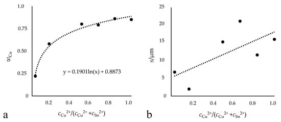
Figure 1.
Illustration of the relationship between electrolyte composition and resulting alloy layer. Amount of copper in the layer (a) and the obtained layer thickness (b). Deposition of Cu−Sn in [EMIM]Cl with different Cu and Sn concentration ratios (0.5 A/dm2, 95 °C, 100 rpm, 10,800 s) outside the glove box.
The literature described the concentrations of the individual metals in the electrolyte as not corresponding to the metal proportion in the obtained alloy deposits [17]. However, this has been shown to not be valid for this electrolyte system, and the individual metal concentrations correspond to their proportion in the deposit. The logarithmic course of the different ratios of the electrolyte concentrations to the resulting alloy composition shows a good agreement with the results from aqueous electrolytes that had been previously described by Brenner for aqueous cyanide Cu−Sn electrolytes ([3], pp. 82, 512). There, the curves denoting the percentage of tin in the deposit lay below an average value at which the alloy composition is comparable to the conditions in the electrolyte, indicating that the percentage of tin in the deposit was lower than the metal percentage of tin in the bath. Therefore, tin is less readily deposited than copper. The results (Figure 1) show the same trend, confirming the statement that copper is preferentially deposited. In aqueous systems, the influence of the concentrations of complexing agents such as hydroxyl and cyanide ions on the potentials of the metals and on their deposition efficiency play a more important role than diffusion phenomena in the composition of the deposit. Similar behaviour is exhibited in the depositions from the ionic liquid, even though no complexing agents were added. This leads to the conclusion that the ionic liquid itself may act as a complexing agent. The obtained Cu−Sn deposit is adhesive and compact over the entire range as shown in Figure 2. The color of the layer ranges from gray with low Cu content to the typical copper red. It was also found that a relatively higher copper-ion concentration in comparison to the tin-ion concentration in the bath creates a thicker layer regardless of the coating time; consequently, a higher growth rate is also found, as seen in the comparison of the three-hour depositions shown here. It was possible to get layer thicknesses of up to 15 µm within the deposition time of 3 h, which corresponds to a mean growth rate of 0.083 µm/min. Up until now, previous studies had only reached a layer thickness of 10 µm in 4 h, a growth rate of 0.04 µm/min [5].
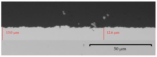
Figure 2.
Optical-microscopic grey scale image of the cross-section from a Cu−Sn layer (0.5 A/dm2, 95 °C, 100 rpm, 10,800 s) with 85% mass fraction of copper deposited outside the glove box.
The layer with the highest copper content as shown in Figure 3 has a rough surface comprised of spherical, well-distributed grains across the entire surface with few visible defects. The formed spheres have an average diameter of approximately 20 µm, which is shown in the top-surface SEM image. The dendritic morphology is usually associated with coatings in which the deposition of copper ions is favored. For aqueous electrolytes, literature reported the morphology of Cu−Sn alloys in the form of spherical grains, needles, or with a dendritic morphology [19,20,21,22]. A morphology that is similar to other IL depositions, e.g., for those of Pd and Pt, was observed [23]. Despite the sphere-like morphology, the deposited layers are compact and adhesive.
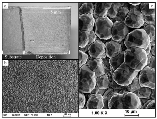
Figure 3.
Deposition of a Cu−Sn alloy on steel substrate (a) and scanning electron microscopy (SEM) images (b,c) with different magnifications of the surface of a Cu−Sn layer (0.5 A/dm2, 95 °C, 100 rpm, 10,800 s) with 85% mass fraction of copper deposited outside the glove box.
Cyclovoltammetric (CV) investigations in [EMIM]Cl with 0.075 mol/L SnCl2 and 0.225 mol/L CuCl2 are shown in Figure 4. These investigations were performed during the regular electroplating process with a platinum sheet serving as the quasi-reference electrode to the anode-cathode arrangement (steel cathode as the working electrode and the tin anode as the counter electrode).
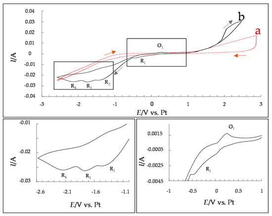
Figure 4.
Cyclovoltammogram in pure [EMIM]Cl electrolyte as background ((a), red) and [EMIM]Cl with 0.075 mol/L SnCl2 and 0.225 mol/L CuCl2 at a sweep rate of 0.01 V/s ((b), black).
In the performed cyclovoltamogramic measurements, there are four reduction peaks located at 0.10 to −0.50 V (R1), −1.20 to −1.35 V (R2), −1.35 to −1.90 V (R3) and −1.90 to −2.40 V (R4). After the deposited layer was examined for its composition, the peaks in the recorded voltammogram were able to be assigned to copper or tin. According to the literature [17], there should be just three reduction peaks. This, combined with the limitations of the conducted investigations, renders it impossible to say with certainty which reduction reaction is responsible for which peak. R1 is likely caused by the reduction of Cu2+ → Cu+. The literature assigned R2 to the reduction peak of Cu2+ and Sn2+ codeposition [17]. The assignments of R3 and R4 are more ambiguous: one of them is probably caused by the reduction of Cu+ → Cu0. The other could stem from the reduction of Sn2+ → Sn0; perhaps in [EMIM]Cl, this reduction is better resolved, resulting in the appearance of a new reduction peak. In the obtained CV, two oxidation peaks can be observed: one between 0 V and 0.5 V and one in the region of 2 V. The first should belong to the oxidation of Cu0 → Cu+, while the latter, when considered in combination with the background/blank measurement, is assumed to belong to the oxidative degradation of the ionic liquid. According to the literature [17], however, there should be a total of three oxidation peaks, the two already described as well as a third peak between them, a peak not found in the [EMIM]Cl-based electrolyte. This absent peak would have shown the oxidation of Cu+, Cu−Sn alloy, and water. One possible explanation for its absence is that no further oxidation, i.e., dissolution, of Cu or Cu−Sn occurs in the system with [EMIM]Cl. Since this reaction cannot be observed here, it also suggests that the electrolyte is less susceptible to the absorption of water. The reduction and oxidation processes that were associated with water (by Jie [17]) are also absent in the presented system, further suggesting that, in contrast to these [BMIM]Cl deposits, the [EMIM]Cl-based electrolyte shown here is less susceptible to water, which is beneficial for deposition outside the glove box. This could enable the deposition of these layers under near-industrial conditions and avoid time-consuming handling in a glove box. In addition, there are also less process-related, oxidative resolutions, which allow for uniform and fast layer growth.
XRD measurements were carried out and a typical diffractogram is shown in Figure 5. The layer shows reflections at 40.4°, 50.0°, 73.4°, 94.0°, and 108.0°, which are attributable to the crystalline Cu41Sn11 phase (PDF 01-071-7876). Two cubic CuSn lattices with slightly different lattice parameters are present-minor shoulders can be observed at the main reflections. This indicates that the cubic phase was deposited with two slightly different compositions. The reflection at 45° is narrow because it corresponds to the Co Kβ reflection of the {660} peak of Cu41Sn11. No matching phase from the PDF-2 database could be assigned to the peak at 52°.
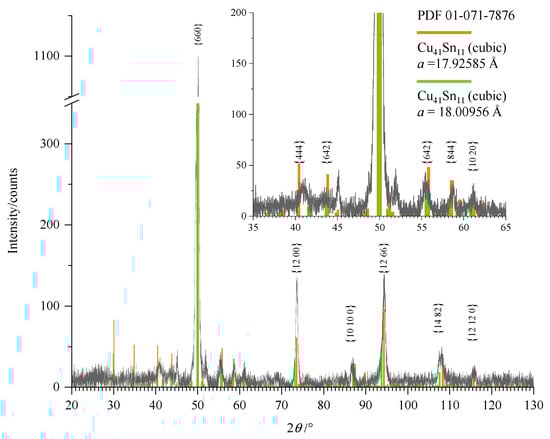
Figure 5.
XRD measurement of a Cu–Sn layer with 85% mass fraction of copper obtained from [EMIM]Cl measured with Co Kα radiation. According to the PDF-2 database (PDF 01-071-7876), the lattice parameter of the Cu41Sn11 phase is 17.964 Å. For the {660} peak, the corresponding peak originating from Co Kβ radiation can be observed as well (at a diffraction angle of about 45°).
Typical EDX results of a Cu−Sn layer are shown in Figure 6. Cu and Sn can clearly be detected in the layer. The spectrum was recorded up to 40 keV and shows peaks of Cu Lα at 0.93 keV, Cu Kα at 8.04 keV, and Cu Kβ at 8.90 keV. For tin, five characteristic peaks were obtained: 0.42 keV of Sn Mα, 3.47 keV of Sn Lα, 3.68 keV and 3.96 keV for SnLβ, and 4.18 keV for SnLγ.
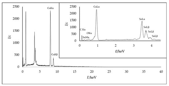
Figure 6.
EDX area measurement of a Cu−Sn layer (0.5 A/dm2, 95 °C, 100 rpm, 10,800 s) with 85% mass fraction of copper.
C and especially O can only be detected outside the layer, in the region of the embedding agent of the cross-section. The oxygen content was measured in the same manner and must be attributed to fast oxidation during the preparation process. As no further signals were detected in the XRD diffractogram and EDX, the results suggest a clear alloy deposition with no crystalline oxides or fragments of the IL incorporated into the layer, demonstrating that it is a pure Sn–Cu system.
4. Conclusions
The deposition was done in [EMIM]Cl ionic liquid for 3 h, at a current density of 0.5 A/dm2 and at 95 °C. Thick compact layers with a thickness of 15 µm were obtained. The layers were examined by optical and electron microscopy, and it was found that the layer consisted of spherical grains. Differences in composition and thickness of the alloy layer are affected by the variation in the metal-salt concentration in the electrolyte. The results prove that an irregular alloy deposition occurs as earlier described by Brenner for complexed electrolytes such as Cu−Sn with cyanides in water [3]. The absence of water has been confirmed by cyclovoltammetry. The resulting layer thickness and alloy composition, which was measured with XRF and OES, have also been confirmed microscopically, with EDX, and XRD. Further tribological tests of these layers could determine whether the layers would be suitable for practical applications. However, the work shows that it is possible to produce thick electrodeposited bronze layers outside of the glove box using ionic liquids. This is a further step towards replacing conventional aqueous electrolytes containing cyanide with ionic liquids. As each deposition was performed in a fresh electrolyte, the ageing behavior was not investigated in this work. This would have to be explored in further work.
Author Contributions
Conceptualization, L.L., D.H., T.M., and T.L.; methodology, L.L., D.H., and T.M.; validation, L.L. and D.H.; formal analysis, L.L. and T.M.; investigation, L.L. and T.M.; writing—original draft preparation, L.L. and D.H.; writing—review and editing, T.M. and T.L.; supervision, T.M. and T.L.; project administration, L.L., D.H., and T.L. All authors have read and agreed to the published version of the manuscript.
Funding
The publication of this article was funded by Chemnitz University of Technology.
Data Availability Statement
The data presented in this study are available on request from the corresponding author.
Acknowledgments
The authors acknowledge the support from the Institute of materials science and materials engineering at the Chemnitz University of Technology. We would like to thank Marc Pügner for the XRD measurements, Steffen Clauß for the SEM measurements, and Morgan Uland for English proofreading.
Conflicts of Interest
The authors declare no conflict of interest.
References
- Larson, C.; Smith, J.R. Recent Trends in Metal Alloy Electrolytic and Electroless Plating Research: A Review. Trans. IMF 2011, 89, 333–341. [Google Scholar] [CrossRef]
- Meng, G.; Sun, F.; Wang, S.; Shao, Y.; Zhang, T.; Wang, F. Effect of Electrodeposition Parameters on the Hydrogen Permeation during Cu–Sn Alloy Electrodeposition. Electrochim. Acta 2010, 55, 2238–2245. [Google Scholar] [CrossRef]
- Brenner, A. Chapter 15—Electrodeposition of Copper-Tin Alloys. In Electrodeposition of Alloys. Principle and Practice; Academic Press: New York, NY, USA; London, UK, 1963. [Google Scholar]
- Walsh, F.; Low, C. A review of developments in the electrodeposition of copper-tin (bronze) alloys. Surf. Coat. Tech. 2016, 304, 246–262. [Google Scholar] [CrossRef]
- Ghosh, S.; Roy, S. Long Term Tin Plating from Eco-Friendly Choline Chloride Ionic Liquid. In Proceedings of the Conference: Electrochemical Techniques for Nano-Scale Surface Engineering, Mumbai, India, 5–6 January 2012. [Google Scholar]
- Endres, F.; MacFarlane, D.; Abbott, A. Electrodeposition from Ionic Liquids; Wiley-VCH: Weinheim, Germany, 2008; pp. 1–12. [Google Scholar]
- Jalalvand, A.R. Fabrication of a Novel and High-Performance Amperometric Sensor for Highly Sensitive Determination of Ochratoxin A in Juice Samples. Talanta 2018, 188, 225–231. [Google Scholar] [CrossRef] [PubMed]
- Matsumiya, M.; Sumi, M.; Uchino, Y.; Yanagi, I. Recovery of Indium Based on the Combined Methods of Ionic Liquid Extraction and Electrodeposition. Sep. Purif. Technol. 2018, 201. [Google Scholar] [CrossRef]
- Guo, Q.; Han, Y.; Wang, H.; Xiong, S.; Liu, S.; Zheng, C.; Xie, K. Preparation and Characterization of Nanocomposite Ionic Liquid-Based Gel Polymer Electrolyte for Safe Applications in Solid-State Lithium Battery. Solid State Ion. 2018, 321, 48–54. [Google Scholar] [CrossRef]
- Höhlich, D.; Mehner, T.; Scharf, I.; Lampke, T. Simultaneous Electrodeposition of Silver and Tungsten from [EMIm]Cl:AlCl3 Ionic Liquids Outside the Glove Box. Coatings 2020, 10, 553. [Google Scholar] [CrossRef]
- Katase, T.; Kurosaki, R.; Murase, K.; Hirato, T.; Awakura, Y. Formation of Cu-Sn alloy layer by contact deposition using quaternary ammonium-imide-type ionic liquid. Electrochem. Solid State Lett. 2006, 9, C69–C72, Erratum in 2006, 9, L5–L6. [Google Scholar] [CrossRef]
- Murase, K.; Kurosaki, T.; Katase, T.; Sugimura, H.; Hirato, T.; Awakura, Y. Electrochemical alloying of copper substrate with tin using ionic liquid as an electrolyte at medium-low temperatures. J. Electrochem. Soc. 2007, 154, D612–D616. [Google Scholar] [CrossRef]
- Hsieh, Y.-T.; Sun, I.-W. Electrochemical Growth of Hierarchical CuSn Nanobrushes from an Ionic Liquid. Electrochem. Commun. 2011, 13, 1510–1513. [Google Scholar] [CrossRef]
- Ito, A.; Murase, K.; Ichii, T.; Sugimura, H. Cu-Sn Alloy Metallization of Polymer Substrate through Reduction-Diffusion Method Using Ionic Liquid Bath at Medium-Low Temperatures. Electrochemistry 2009, 77, 677–679. [Google Scholar] [CrossRef]
- Murase, K.; Ito, A.; Ichii, T.; Sugimura, H. Preparation of Cu-Sn Layers on Polymer Substrate by Reduction-Diffusion Method Using Ionic Liquid Baths. J. Electrochem. Soc. 2011, 158, D335. [Google Scholar] [CrossRef]
- Ghosh, S. Electrodeposition of Cu, Sn and Cu-Sn Alloy from Choline Chloride Ionic Liquid; University of Newcastle: Newcastle, UK, 2013. [Google Scholar]
- Jie, S.; Ting-yun, M.; Hui-xuan, Q.; Qi-song, L. Electrochemical Behaviors and Electrodeposition of Single-Phase Cu-Sn Alloy Coating in [BMIM]Cl. Electrochim. Acta 2019, 297, 87–93. [Google Scholar] [CrossRef]
- Höhlich, D.; Wachner, D.; Müller, M.; Scharf, I.; Lampke, T. Electrodeposition and Characterisation of Al-W Alloy Films from Ionic Liquid. IOP Conf. Ser. Mater. Sci. Eng. 2018, 373, 012007. [Google Scholar] [CrossRef]
- Han, C.; Liu, Q.; Ivey, D.G. Nucleation of Sn and Sn–Cu Alloys on Pt during Electrodeposition from Sn–Citrate and Sn–Cu–Citrate Solutions. Electrochim. Acta 2009, 54, 3419–3427. [Google Scholar] [CrossRef]
- Zanella, C.; Xing, S.; Deflorian, F. Effect of Electrodeposition Parameters on Chemical and Morphological Characteristics of Cu–Sn Coatings from a Methanesulfonic Acid Electrolyte. Surf. Coat. Technol. 2013, 236, 394–399. [Google Scholar] [CrossRef]
- Meudre, C.; Ricq, L.; Hihn, J.-Y.; Moutarlier, V.; Monnin, A.; Heintz, O. Adsorption of Gelatin during Electrodeposition of Copper and Tin–Copper Alloys from Acid Sulfate Electrolyte. Surf. Coat. Technol. 2014, 252, 93–101. [Google Scholar] [CrossRef]
- Correia, A.N.; Façanha, M.X.; de Lima-Neto, P. Cu–Sn Coatings Obtained from Pyrophosphate-Based Electrolytes. Surf. Coat. Technol. 2007, 201, 7216–7221. [Google Scholar] [CrossRef]
- Böck, R.; Lanzinger, G.; Freudenberger, R.; Mehner, T.; Nickel, D.; Scharf, I.; Lampke, T. Effect of Additive and Current Mode on Surface Morphology of Palladium Films from a Non-Aqueous Deep Eutectic Solution (DES). J. Appl. Electrochem. 2013, 43, 1207–1216. [Google Scholar] [CrossRef]
Publisher’s Note: MDPI stays neutral with regard to jurisdictional claims in published maps and institutional affiliations. |
© 2021 by the authors. Licensee MDPI, Basel, Switzerland. This article is an open access article distributed under the terms and conditions of the Creative Commons Attribution (CC BY) license (http://creativecommons.org/licenses/by/4.0/).