Review

A Review on the Processing Technologies for Corrosion Resistant Thermoelectric Oxide Coatings

Department of Mechanical Engineering, College of Engineering, California State Polytechnic University Pomona, 3801 W Temple Avenue, Pomona, CA 91768, USA
Coatings 2021, 11(3), 284; https://doi.org/10.3390/coatings11030284
Submission received: 19 January 2021 / Revised: 14 February 2021 / Accepted: 24 February 2021 / Published: 28 February 2021
(This article belongs to the Special Issue Advances in Corrosion Resistant Coatings)

Abstract

:
Oxide coatings are corrosion resistant at elevated temperatures. They also show intensive phonon scattering and strong quantum confinement behavior. Such features allow them to be used as new materials for thermoelectric energy conversion and temperature measurement in harsh environments. This paper provides an overview on processing thermoelectric oxide coatings via various technologies. The first part deals with the thermoelectricity of materials. A comparison on the thermoelectric behavior between oxides and other materials will be made to show the advantages of oxide materials. In the second part of the paper, various processing technologies for thermoelectric metal oxide coatings in forms of thin film, superlattice, and nanograin powder will be presented. Vapor deposition, liquid phase deposition, nanocasting, solid state approach, and energy beam techniques will be described. The structure and thermoelectric property of the processed metal oxide coatings will be discussed. In addition, the device concept and applications of oxide coatings for thermoelectric energy conversion and temperature sensing will be mentioned. Perspectives for future research will be provided as well.

1. Introduction

Thermoelectric materials can generate electricity when a temperature difference exists. Such a function allows a thermoelectric module to be used as an energy converter [1] or thermal sensor [2]. For the energy conversion application, the module can be used either as an electrical power generator [3] or as a cooler [4]. The thermoelectric property of a material may be evaluated by a characteristic parameter called the thermoelectric figure of merit z, which can be expressed as the following equation [5]:
z = σ S 2 κ
where S is the Seebeck coefficient, κ is the thermal conductivity, and σ is the electrical conductivity. Based on the definition of z, the thermoelectric energy conversion performance of a material can be quantified by a dimensionless figure of merit zT: The calculation of zT is shown as follows:
z T = σ S 2 κ T
where T is the absolute temperature. It is estimated that a zT value of 1.0 corresponds to an energy conversion efficiency around 10%.
Many researchers have studied materials processing and module manufacturing technologies with the aim of identifying high efficiency thermoelectric energy conversion materials and systems. Metallic alloys and intermetallic compounds are the most commonly researched thermoelectric (TE) materials. Among various metallic TE materials, skutterudites (named after the city of Skotterud, Norway), a cobalt arsenide mineral containing variable amounts of nickel and iron substituting for cobalt with a general formula of CoAs3, shows considerably strong thermoelectric effect in the temperature range from 400 to 600 °C with the zT values as high as 0.85 at 400 °C and as high as 1.9 at 550 °C for doped skutterudites [6]. Another group of TE metallic materials consists of the Half-Heusler (HH) alloys. Heusler alloys are named after the German mining engineer and chemist Friedrich Heusler who investigated Cu-Mn-Al alloys in 1900s. They are magnetic intermetallic compounds with the face-centered cubic (FCC) crystal structure. Some of these alloys are ferromagnetic even though their constituent atoms are non-ferromagnetic as elements. There are three families of Heusler alloys, i.e., full Heuslers with the general formula of “A2BC”, Half-Heuslers (HH) with the chemical composition of “ABC”, and inverse Heuslers with the “ABAC” formula. Half-Heusler (HH) compounds based on XNiSn and XCoSb (X = Ti, Zr, or Hf) have increasing importance as thermoelectric materials for converting waste heat into electricity [7,8,9]. This is because the figure of merit, zT, for some Half-Heusler (HH) alloys, for example, Ti0.5Zr0.5NiSn and Ti0.15Nb0.85FeSb is as high as 0.8 and the thermoelectric conversion efficiency, η, is enhanced close to 10% [10,11,12].
Chalcogenides are covalently bonded compounds containing one or more chalcogen elements (S, Se, Te, or Po) as a substantial constituent. A recent review on chalcogenides as thermoelectric materials was published [13]. It is reported that the outstanding thermoelectric performance of chalcogenides depends strongly on the decrease in thermal conductivity. The thermal conductivity reduction in some chalcogenides, for example, PbTe [14], is due to the existing heavy elements. However, it has been found that in some other cases (e.g., Tl(10−x)SnxTe6 and Tl(10−x)PbxTe6 [15]) heavy elements are not the major contributors to the low thermal conductivity. Instead, the stereo chemically active lone pair is the main reason for low thermal conductivity as found in the SnSe compound [16,17]. The high ion mobility also contributes to the low thermal conductivity. Cu or Ag cations exhibit good ion mobility in thermoelectric materials such as Cu2Se [18], Ba3Cu(14−δ)Te12 [19], and Tl2Ag12Se7 [20].
In general, a good thermoelectric material is an “electron crystal and phonon glass” which has high electrical conductivity and low thermal conductivity at the same time. Among various materials, semiconducting silicon and its related compounds (both metallic and nonmetallic silicates) show such unique behavior, which means that the thermal conductivity and electrical conductivity are decoupled. Doped-silicon has good conductivity, comparable to that of a metal, but keeps very low thermal conductivity, like that of a ceramic material [21]. Zhou and Hu [22] predicted the further reduction of the thermal conductivity of polycrystalline Si nanowires by introducing disorders to cause more effective phonon scattering. Metal silicates and their nanocomposites have been reported to possess high thermoelectric figure of merit (zT) values because of their low thermal conductivity and high Seebeck coefficient values [23,24,25,26,27,28,29].
Compared to the aforementioned thermoelectric materials, most of the metal oxides exhibit modest thermoelectric properties due to their relatively low electrical conductivity and high thermal conductivity. However, metal oxides have good high temperature stability in air. They are almost inert in various corrosion media. In addition, they are easy to process and inexpensive. Such advantages provide the motivation to search for good thermoelectric material-based oxides. Several groups of oxide materials including binary oxides, perovskite oxides, and oxidized bismuth selenide have demonstrated promising thermoelectric performance as described in [30]. It is revealed that some of the layered oxides have certain advantages in view of their peculiar transport behavior [31]. A review of various layered oxides for thermoelectric applications is presented in [32]. Numerical studies on the structural stability and thermoelectric property of the Ca-Mn based oxide were reported [33].
Metal oxides have been extensively used to build multiple functional devices, for example, photovoltaic/thermoelectric duel functionality modules based on the photo-Seebeck effect [34,35,36]. As reported by Shiraishi et al. [37], the photo-Seebeck effect in the perovskite titanium oxide, SrTiO3, leads to the high mobility of the photon-induced electrons by the 405 nm laser excitation, which is considered as an additional contribution to the increased electrical conductivity. In addition, the absolute value of the Seebeck coefficient was found very high, i.e., in the range from 0.25 to 2.2 mV/K under the 450 nm laser illumination. In some other oxide based thermoelectric materials with different compositions and structures [38,39,40,41,42,43], how the photon-induced carriers contribute to the thermoelectric behavior, i.e., the photo-Seebeck effect was examined as well. For example, the wide-gap oxide semiconductor ZnO shows the strong photo-Seebeck effect [38,39,40]. Okazaki et al. [38] investigated ZnO by measuring its electrical conductivity and Seebeck coefficient under light illumination. Both Seebeck coefficient and conductivity of the oxide were found sensitive to the photon energy of the illumination light sources. A parallel-circuit model was used to evaluate the contributions from the photo-induced carriers to the conductivity and the Seebeck coefficient. It was found that the results obtained from their studies are similar to those from doped semiconductors. That is, the light illumination increases both the carrier concentration and the mobility, as also found in doped ZnO with impurities.
Another important wide-band gap oxide, WO3, also demonstrates the photo-Seebeck effect [41,42]. Suzuki et al. [41] measured the thermoelectric power of a platinum-loaded tungsten trioxide (Pt/WO3) thin film exposed to an ultraviolet (UV) light source. The UV light-induced band-gap excitation was observed. It has been found that the electrical conductivity (σ) is increased, whereas the absolute value of the Seebeck coefficient (S) is decreased due to the photochromic reactions in WO3. The opposite behavior, a decrease in σ and an increase in S, was observed in the presence of O2 after dark storage. Photo-Seebeck effect was also detected in response to the visible-light irradiation of a Pt/WO3 specimen in the absence of O2 after chromic reactions. Under visible-light irradiation, both σ and the absolute value of S were increased.
Mondal et al. [43] observed the photo-Seebeck effect in tetragonal PbO single crystals. The photo-induced carrier concentration was modeled. Transport data were obtained by measurement. It is confirmed that photo-induced carriers contribute to the change in the transport behavior. The electrical conductivity increases by more than two orders in magnitude, but the Seebeck coefficient decreases from 1.9 to 0.8 mV/K with the increase of the photon flux density. The power factor (σS2) increases under illumination. The photo-induced carrier concentration increases almost linearly with the increase of photon flux density. The power factor was found increasing due to the synergistic photo-doping effect on the thermoelectric property of PbO. The career mobility decreases by illumination, and the reduction rate strongly relies on the photon energy of the illumination source.
In view of metal oxide processing and manufacturing technologies, the powder metallurgical method [44,45,46,47] is especially suitable for making bulk oxides. For metallic oxide coatings, liquid phase processing [48,49], vapor phase deposition [50], energy beam technique [51], and high temperature or molten metal electrochemical oxidation [52] have been widely used. There are some other techniques developed for metal oxide coating preparation. For example, solution-gelation approach [53], electrodeposition or electroplating [54], electrospinning [55], liquid phase deposition [56], templated assisted nanocasting [57], pulsed laser deposition [58], and low temperature electrochemical processing [59] have been utilized.
This paper deals with the advances in the thermoelectric oxide coatings with the emphasis on processing technologies. The rest of the paper is organized as follows. A review on the processing and manufacturing techniques for thermoelectric metal oxide nanomaterials will be introduced first. Thermoelectric oxide coatings consisting of thin films, nanopowders, superlattices, and low dimensional heterogeneous oxides [60] will be presented. Device fabrication and characterization of the thermoelectric properties of oxide coatings will be briefly introduced following the discussion on processing and manufacturing technologies in each subsection. Perspectives to future research directions will be discussed and concluding remarks will be drawn.

2. Thermoelectric Oxide Coating Processing Technologies

There are many methods for oxide coating preparation and manufacturing. In this part, the commonly used vapor deposition including physical and chemical vapor deposition, solid state approach, liquid phase deposition, nanocasting, and energy beam techniques including laser beam deposition, ion beam sputtering, and electron beam evaporation will be introduced.

2.1. Vapor Phase Deposition

Vapor-phase deposition consists of physical vapor deposition (PVD), chemical vapor deposition (CVD), plasma enhanced deposition (PED), magnetic field enhanced deposition (MFED) etc. There are two major types of physical vapor deposition (PVD), thermal evaporation and sputtering. Both thermal evaporation and sputtering can deliver uniform coatings. Chemical vapor deposition (CVD) consists of ambient pressure CVD, low pressure CVD, metal organic compound CVD (MOCVD), etc. The plasma technique can be integrated into both PVD and CVD to achieve the so-called plasma-enhanced deposition. The plasma effect can change the deposition rate significantly. Magnetic field enhanced deposition (MFED) is suitable for increasing the deposition rate of oxide materials that are sensitive to an externally added magnetic field. The deposition of transition metal oxide coatings such as NiO, CoO, and Fe2O3 can benefit from an added magnetic field because the deposition rate could be increased more than 500 times. Vapor-phase deposition, as described in the review article [50], has been extensively studied for preparation of oxide coatings. It is considered as one of the least expensive ways for large scale production due to the use of simple, cost-effective equipment. This technique is suitable for synthesizing various oxide coatings consisting of either wide-band or narrow-band oxide compounds. Typical examples of oxide coatings processed by vapor phase deposition include but are not limited to titanium dioxide (TiO2) [61], zinc oxide (ZnO) [62], alumina (Al2O3) [63], tin dioxide (SnO2) [64], copper oxide (CuO) [65], gallium oxide (β-Ga2O3) [66], and hematite (α-Fe2O3) [67]. Some other oxides such as indium oxide (In2O3) [68], cadmium oxide (CdO) [69], and ceria (CeO2) [70] can also be processed by this technique.
In the work performed by Ahmoum et al. [71], nickel-doped zinc oxide was made by thermal co-evaporating of Ni and Zn in O2 flow under different temperature conditions. Alumina was used as the substrate and kept at 300 °C during the co-evaporation deposition. The temperature of Zn source was maintained at 350 °C. The Ni source (particles with a diameter around 1–3 mm) was heated up to different temperatures of 1230, 1250, and 1270 °C. The initial pressure of the chamber was 8.5 × 10⁻⁵ Pa, and the working pressure during the deposition was kept at 1.2 × 10⁻⁴ Pa. The radio-frequency power was set at 380 W and the rate of O2 flow was 1.8 SCCM to produce reactive oxygen atoms. The thicknesses of the Ni-doped ZnO film reached 740 nm after 350 min deposition. The electrical conductivity was measured in the temperature range from 50 to 300 °C. The result can be found in Figure 1a [71]. With the test temperature increasing, the electrical conductivity showed a general increasing trend. The specimen deposited at the Ni source temperature of 1250 °C showed the highest conductivity. This specimen also showed the most increase of the electrical conductivity when the test temperature was raised. Its conductivity increased from 1800 to 3200 (S/m). The Seebeck coefficient data were presented in Figure 1b for the Ni-doped ZnO [71]. The specimens deposited at different Ni-source temperatures are n-type. The higher the Ni-source temperature during deposition, the stronger the Seebeck effect. The absolute value of the Seebeck coefficient increases slightly with the increasing in the testing temperature.
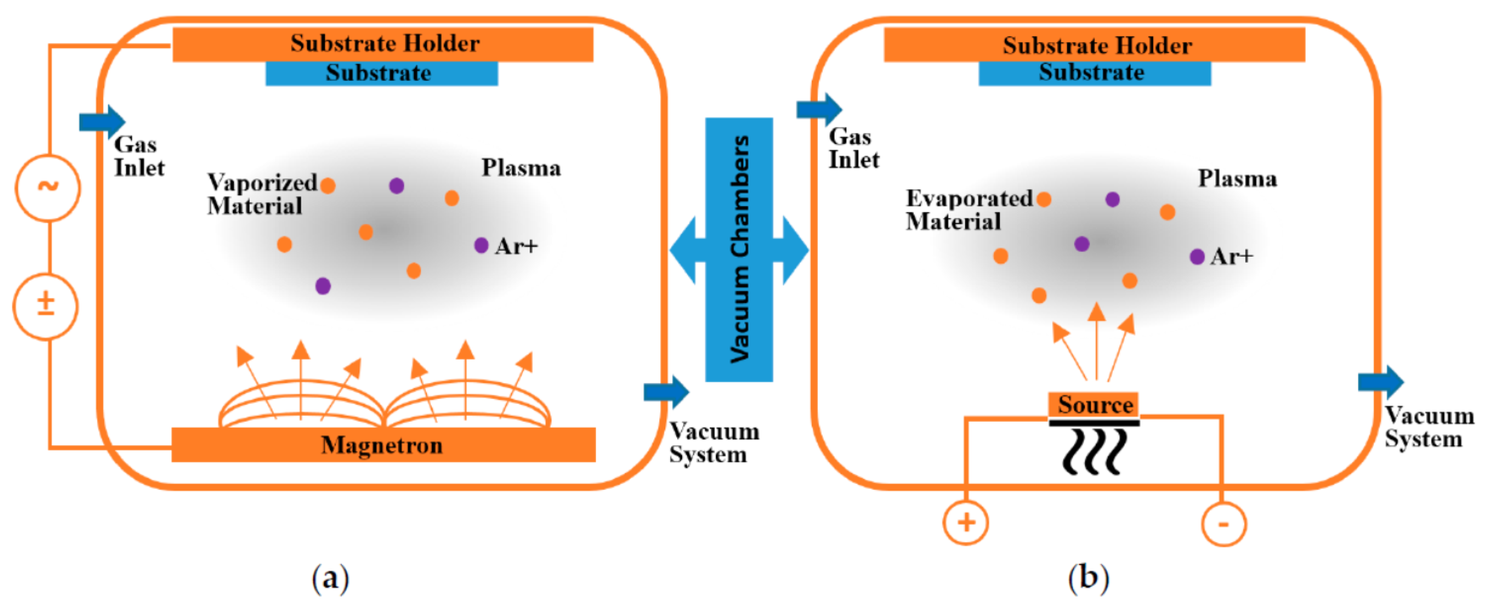
Many deposition techniques used for device fabrication allow the formation of multilayer coatings. They can be grouped into two large groups: Physical Vapor Deposition (PVD) and Chemical Vapor Deposition (CVD). CVD generally consists of introducing gaseous reagents into a reactor or deposition chamber. The reagents cause chemical reactions to occur on the surface of the material to be coated. This process leads to the growth of a coating on the surface of a substrate. Physical Vapor Deposition (PVD) includes a group of deposition techniques, which are common on the aspect that they allow the mass transport from a target material or a source material to the substrate to be coated. The process takes place in a compact chamber. Although thermal evaporation and plasma sputtering are the frequently used PVD techniques, integrating two or several processes together has caught more and more intention because of the advantage of the enhanced deposition rate. Typical integrated methods include magnetron plasma sputtering and plasma sputtering coupled with thermal evaporation. Figure 2 schematically shows the setups for these two integrated PVD techniques with more details available in [72].
As compared to PVD, CVD is a much faster process for oxide coating deposition. It is considered as one of the most useful micro- and nanoscale fabrication techniques [4]. During CVD process, heterogeneous reactions may take place not only on a substrate but also in the gaseous phase. Therefore, the deposition rate is high, but the uniformity of the coatings may be low. A typical chemical vapor deposition process includes several stages. In the first stage, reactants and inert dilute gases flow into the chamber. In the second stage, gaseous species move towards the substrate and reactants adsorb onto the substrate. Then, adsorbed atoms migrate and participate into chemical reactions. The gaseous by-products of the reactions are desorbed from the surface of the specimens and removed from the reaction chamber. Finally, the exhaust is trapped by a recycling tank connected with a vacuum pump. To control the temperature precisely at different locations in the chamber, multi-zone resistant heaters may be used.
The deposition kinetics in a CVD process highly relies on the temperature condition. In the high-temperature range, the mass transfer controls the rate of deposition. In the low-temperature range, the chemical reaction determines the deposition rate. Transition between the two mechanisms in the intermediate temperature range can be found. Thus, the CVD kinetics can be divided into three regimes [3]. They are the mass transfer-limited regime, the reaction rate-limited regime, and the regime of transition between the previous two, which can be revealed by the relationship of logarithm deposition rate vs. the reciprocal of the reaction temperature. It is found that in the mass transfer limited regime, if CVD reactants arrive at the surface of specimens uniformly, the rate of deposition is not so sensitive to the temperature change. However, in the reaction rate limited region, the rate of deposition is highly sensitive to the temperature. It is very important to keep a uniform temperature distribution in the reaction zone to ensure the uniform deposition. Understanding such kinetics will help control the dimension, morphology, and structure of metal oxide coating products fabricated via CVD.
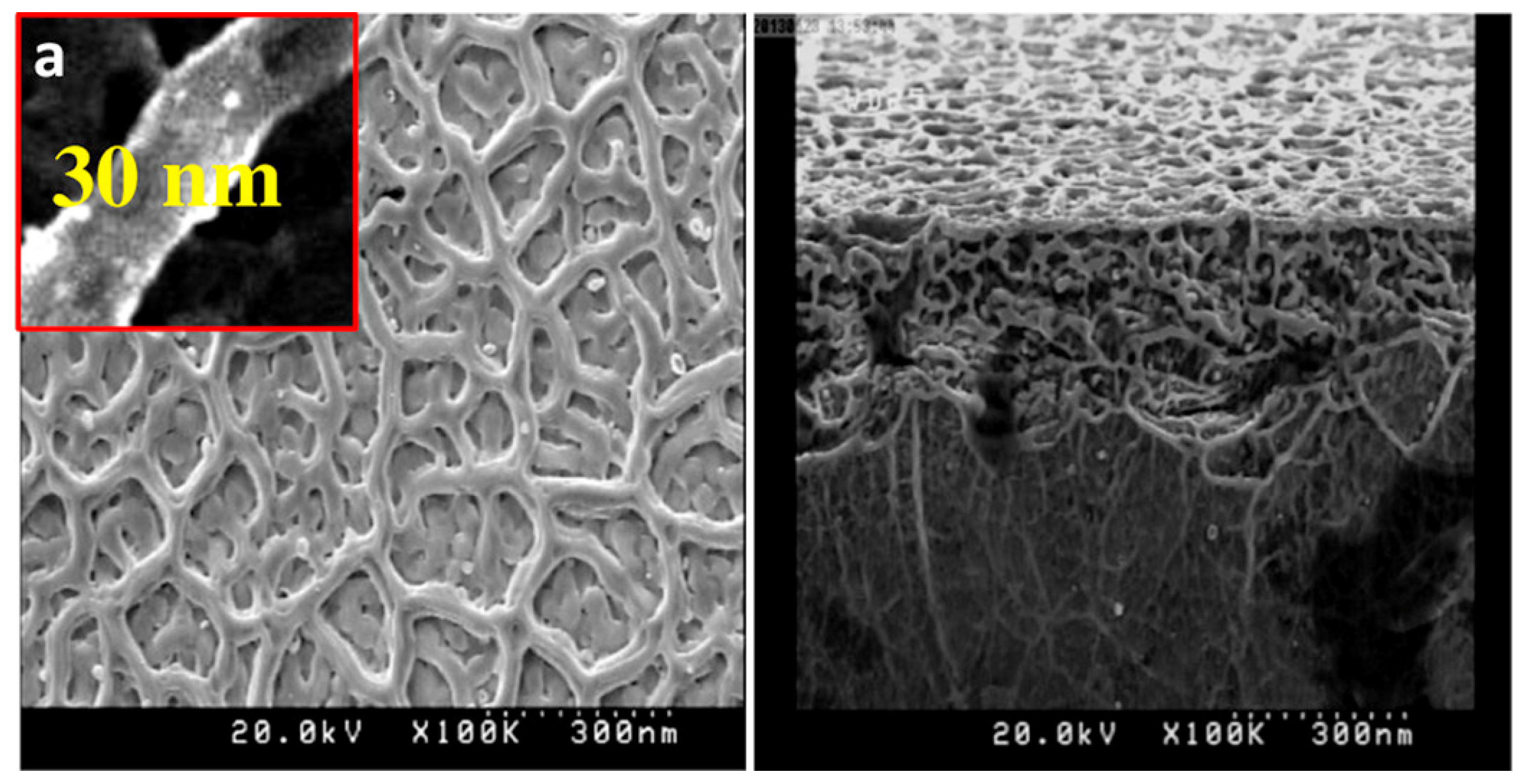
In the vapor deposition category, the chemical spray pyrolysis technique may be considered as one of the derived forms from chemical vapor deposition [73,74,75,76]. Another derived method is the reactive sputtering [77]. Such deposition methods are scalable and cost-effective. A precursor solution containing a metal organic compound or a metal salt dissolved into a solvent is chosen for the spraying or sputtering deposition. The substrate may be heated up at high temperatures, which allows organometallic compounds or inorganic metal salts to decompose in controlled atmospheres for oxide formation. Although these techniques are mainly developed for the deposition of oxide films, the spray pyrolysis deposition (SPD) has been successfully used for preparing titanium dioxide (TiO2) nanofibers [78]. Under the careful controlled spraying rate, titanium dioxide nanofibers with a diameter of 30 nm in the coating were obtained on a hot glass substrate at 350 °C [78] The morphology of the deposited coating was analyzed. Two scanning electron microscopic images are shown in Figure 3. Both the top surface (left hand side image in Figure 3) and cross section (right hand side image in Figure 3) of the coating revealed the fibrous structure. From the inset (a) in the left-hand side image of Figure 3, it can be seen that the transverse size of the fiber is around 30 nm [78].
The precursor used for titanium dioxide coating synthesis was a 0.1 M TiCl3 ethanol alcohol solution. A small amount of distilled water was added into the solution to initiate and sustain the following hydrolysis reaction of the titanium chloride.
2TiCl3 + H2O→Ti(OH)2Cl2 + TiCl4
One of the products from the hydrolysis reaction, Ti(OH)2Cl2, decomposes into titanium dioxide (TiO2) following the reaction formula below, as also presented in [78].
Ti(OH)2Cl2⟶TiO2 + 2HCl↑
It is also shown that titanium dioxide coating containing nano-pyramids can be made by the ultrasonic spray pyrolysis deposition on a glass substrate at an even higher temperature of 460 °C [79]. Pulsed solution feeding was used to spray a precursor solution containing titanium (IV) isopropoxide (TTIP) as the titanium source, acetylacetone (AcAc) as the stabilizer and ethanol as the solvent [80]. The concentration of TTIP in the ethanol solution was 6% in volume, and the molar ratio of TTIP to AcAc was kept as 1 to 2. The solution was vaporized by a pneumatic spray system using compressed air as the carrier gas. TiO2 coatings on silicon substrate were obtained by the spray pyrolysis deposition at different substrate temperatures. The thickness of the coatings was controlled by the number of spray pulses. X-ray diffraction (XRD) experiments confirmed that the as-deposited TiO2 coatings grown at temperatures below 500 °C were amorphous. At the deposition or annealing temperature of 500 °C or above this temperature, the TiO2 coatings showed the crystalline anatase phase structure and were free of contaminants. Annealing at a higher temperature of 700 °C in air resulted in crystalline anatase structure formation for those films deposited even below 400 °C. Films prepared at 435 °C and annealed at 500 °C may show a hybrid structure of both rutile and anatase. More information of the spray pyrolysis deposition may be found in [81]. It is noted that the spray pyrolysis deposition typically includes a sol-gel process before the pyrolysis [82,83,84,85]. The sol–gel process allows the hydrolysis of metallic compounds to form the titanium dioxide coatings in the subsequent pyrolysis stage.

2.2. Liquid Phase Deposition

Liquid phase deposition (LPD) [3,4,86,87,88,89,90,91] is a one-step, low-cost method for metal oxide coating preparation. Typically, the hydrolysis or decomposition of a metalorganic compound or metal complex leads to the metal oxide coating deposition on a substrate. For the one-step deposition of TiO2 film, a mixed solution consisting of ammonium hexafluorotitanate (NH4)2TiF6 (AHFT) and boric acid (BA) was used [91]. The hydrolysis reaction as shown below leads to the oxide film deposition on a substrate such as alumina.
[TiF6]2− + 2H2O ↔ TiO2 + 6F + 4H+
To shift the hydrolysis to the right side of the equation, the F ions should be consumed, which is achieved by the reaction generated by the added boric acid via Equation (6):
H3BO3 + 4H+ + 4F = [BF4] + H3O+ + 2H2O
Gao et al. [90] used LPD to make strontium titanium oxide: SrTiO3 (STO) thin films from an aqueous solution containing a metal-fluoro complex. The metal-fluoro complex was slowly hydrolyzed by adding water and boric acid (H3BO3). Boric acid (BA) served as a fluorine scavenger destabilizing the fluoro-complex, and it promoted the precipitation of the oxide. The metal-fluoro complex was made using the 98.5% purity ammonium hexafluorotitanate (NH4)2TiF6 (AHFT), boric acid (BA), and 98% purity strontium nitrate (SN). First, these compounds were dissolved into deionized water separately. Then, a homogenous solution was made by mixing them together. The concentrations of the three substances in the solution were 25 mM AHFT, 25 mM SN, and 75 mM BA, respectively. Thus, the molar ratios were kept as AHFT:SN:BA = 1:1:3. Deposition of the solid phase was achieved by contacting one side of a p-type silicon wafer with the top surface of the solution. The deposition process was carried out at 50 °C for 3 to 4.5 h. The as-deposited thin film was amorphous, but it can be converted into the crystallized STO through annealing in air at 500 °C for 2 h.
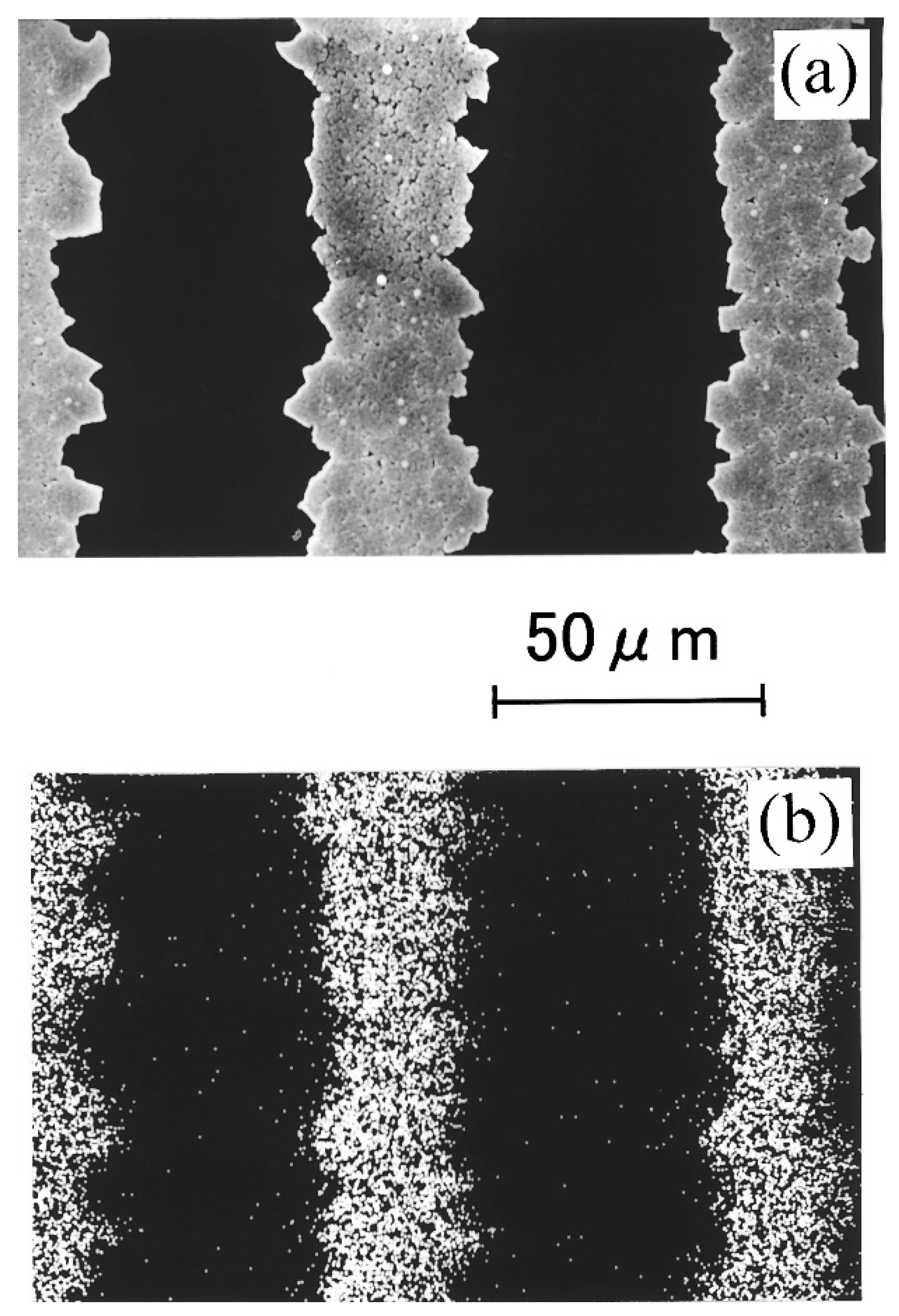
Koumoto et al. [88] showed their work on micropatterning of titanium dioxide on self-assembled monolayers using the liquid-phase deposition (LPD) technique. Figure 4 shows the image and the composition profile of liquid phase deposited titanium dioxide micropatterns [88]. Figure 4a illustrates the edge roughness of the pattern. Figure 4b is the energy dispersive X-ray diffraction map, showing the titanium element signal. The bright areas (hydrophilic regions) correspond to deposited TiO2. The absence of signal (corresponding to the instrument noise level) in the dark areas (hydrophobic regions) signifies the complete removal of TiO2 following sonication [88]. Pure TiO2 self-assembling coatings can be made by the liquid phase deposition technique using the following similar starting materials: ammonium hexafluorotitanate (NH4)2TiF6 (AHFT), boric acid (BA), and water as shown in more details in [88].
Metallic nanoparticles may be co-deposited into the TiO2 films. As reported by Deki et al. [89], gold dispersed titanium dioxide coatings were prepared by the liquid phase deposition. It is also possible to synthesize Si(1−x)TixO2 thin films with gradient composition profiles by liquid phase deposition [87]. The complex oxides were obtained by deposition from the solution which was made by dissolving multiple compounds in a concentrated HF aqueous solution. A very similar example for deposition of multi-component coatings such as (La, Sr)MeO3 (Me = Cr, Mn, Fe, and Co) can be found in the work performed by Yao et al. [86]. First, the (La, Sr)MeO3 solid was prepared by powder sintering. Then, the powder product was dissolved in hydrofluoric acid to produce fluorocomplexes. Then, boric acid was added to the solution to form BF4. The boric acid induced reaction and consumed the fluoride ions effectively. Consequently, the metal fluorocomplexes were hydrolyzed to produce the (La, Sr)MeO3 solid. X-ray diffraction experiments confirmed that the structure of the resulted (La, Sr)MeO3 coatings showed the high crystallinity of a solid solution.
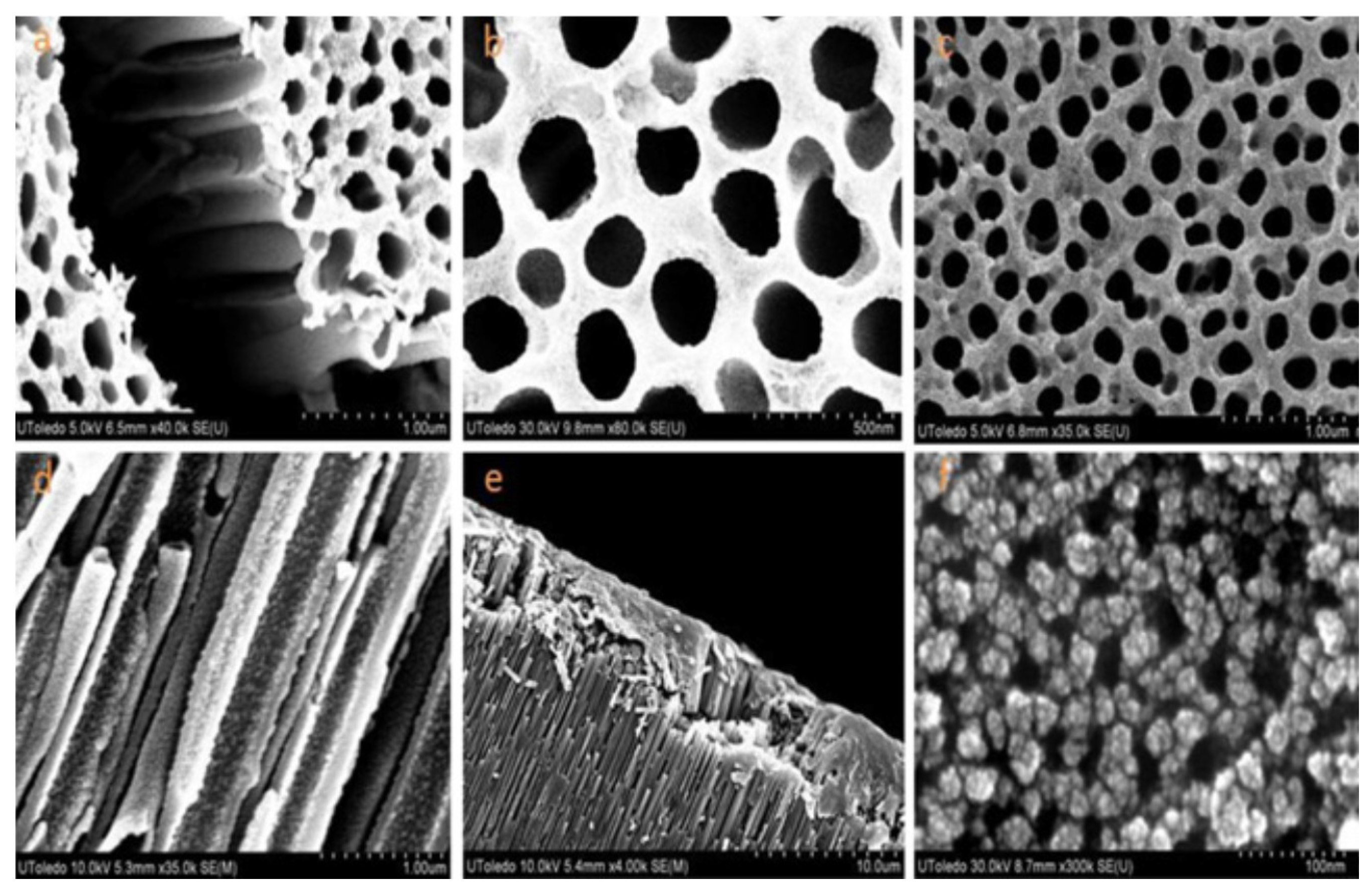
Su et al. [91] prepared a heterogeneous thermoelectric nanocomposite with a TiO2 sheath coating on a CoO nanotube core by the liquid phase deposition technique. First, the TiO2 coating was deposited on the inner walls of the pores within an anodic aluminum oxide (AAO) membrane with a pore diameter of 20 nm. Before the deposition of the TiO2 nanocoating via liquid phase deposition (LPD), both sides of the AAO membrane were covered with a self-assembled monolayer to prevent the deposition of the TiO2 particles on the top and bottom surfaces of the AAO membrane. Consequently, the TiO2 nanocoating only formed on the inner walls of the nanopores rather than on the two flat surfaces of the AAO membrane. The self-assembled monolayer was prepared by mixing 10 mM octadecyltetrachlorosilane in 50 mL of hexane solution. After that, a layer of the TiO2 nanocoating was generated by immersing the treated AAO membrane with the monolayer into 10 mL of a mixed aqueous solution containing 0.05 M (NH4)2TiF6 and 0.1 M H3BO3 for about 30 min to make sure that the TiO2 nanocoating within the nanopores reached the required thickness. The addition of the H3BO3 acid was found to accelerate the TiO2 deposition. The deposited AAO membrane was washed with deionized (DI) water several times and dried completely. The acquired AAO membrane was then heated at 550 °C for 2 h. The heat treatment allowed the crystallization of TiO2 nanocoating. Figure 5a provides a top view of the crystalized TiO2 nanocoating.
To promote the hydrolysis of the (NH4)2TiF6 compound, the fluorine ions in the solution should be consumed to ensure the formation of the TiO2. The added boric acid exactly served the role of fluorine ion scavenger. In order to enhance the thermoelectric performance of the composite material, Ag precipitations were generated and placed into the TiO2 nanotubes to reduce the electrical resistivity. To generate fine Ag nanoparticles and make sure they are dispersed uniformly on the inner wall of the TiO2 nanotubes, TiO2-AAO was dipped into 10 mL of 0.05 M AgNO3 solution. After being washed with DI water and dried, it was heated at 500 °C for 1 h. AgNO3 decomposed and produced Ag nanoparticles (NPs). These particles are distributed uniformly into the inner wall of the TiO2 nanotubes. Figure 5b provides the top view of the silver nanoparticle-containing TiO2 nanotubes (NTs). The Ag particles may not be easily seen due to their tiny sizes.
The deposition of the CoO inside the TiO2 followed the steps as described below. A self-assembled monolayer was applied again to prevent the uneven deposition of CoO on the top and bottom surfaces of the AAO template decorated with TiO2 in the form of thin walled nanotubes (NTs) and/or Ag (NPs). The self-assembled monolayer was the same as mentioned above. The AAO template with TiO2 nanocoating and/or Ag (NPs) was immersed into 10 mL solutions of 0.05 M Co(NO3)2 for 20 min to obtain TiO2-Ag-CoO nanocables. After the Co2+ ions and NO3 ions were impregnated into the TiO2 nanotubes, the template was air-dried. Then, it was heated at 450 °C for 30 min to obtain CoO@TiO2 bilayer nanotubes. This method can be used to deposit pore CoO thin layer into the inner wall of pores in AAO. The CoO nanotubes within the AAO were observed and an SEM image is shown in Figure 5c. The top view of the specimen presents the structure with a fairly smooth surface. The cross section view of the CoO@TiO2 bilayer nanotubes can be found in Figure 5d. These nanotubes have a core/shell nanocable structure with some precipitates inside the wall of the pores. After the CoO@TiO2 bilayer nanotube sample was sputtering coated with Au thin film, the side view was shown in Figure 5e, and the top surface of the Au-coated CoO@TiO2 bilayer nanotube specimen was revealed in Figure 5f [91].
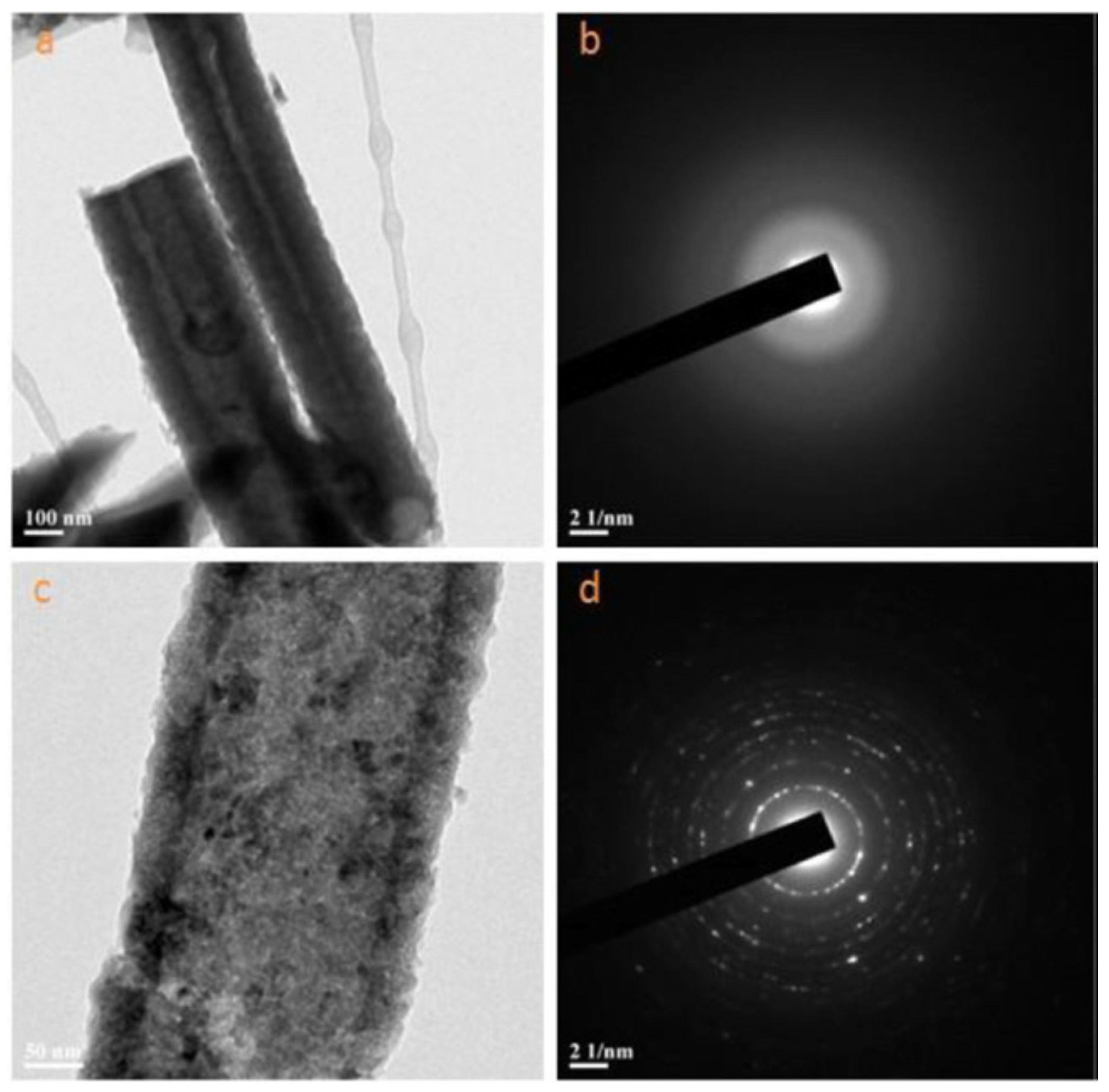
It must be noted that, by dissolving the AAO template into the solution with H+ and F ions, the TiO2-CoO nanocables can be released. The dissolution of the AAO substrate in the solution follows the reaction described in [91]. Figure 6 shows the high-resolution transmission electron microscopic (TEM) images. In Figure 6a, the TiO2 nanotubes without the high temperature heat treatment are shown. Figure 6b reveals the diffraction pattern of the heat treated TiO2 nanotubes. As can be seen from the diffraction pattern that the untreated tubes are amorphous. In Figure 6c, the TEM image of the heat treated TiO2-CoO nanocables is shown, and Figure 6d represents the diffraction pattern of the heat treated TiO2-CoO nanocables. Obviously, crystallization during the high temperature treatment on the TiO2 and CoO happened because the selected X-ray diffraction pattern came from crystalline phase or phases [91].
To measure the Seebeck coefficients of the TiO2-CoO nanocomposite samples, the two ends of each sample were bonded to strips of Al foils using a silver-based conductive adhesive. The aluminum foil strips can provide good conductive property at the composite/electrode interfaces. One end of the Al foil as the hot end was heated up to a required temperature. The hot end temperature ranged from 40 to 130 °C in the experiments. The other end (cold end) was kept at the ambient temperature of 25 °C [91]. The Seebeck coefficients at different temperatures were calculated for the four AAO-based nanocomposite specimens (named TiO2, CoO, TiO2/Ag and TiO2/Ag/CoO) [91]. The calculated results, as listed in Table 1, show that the AAO-based TiO2 + Ag has the highest absolute value of Seebeck coefficient, which may be due to the enhanced electrical property due to the incorporation of the Ag nanoparticles. These highly conductively metallic nanoparticles possess a high density of electrons under thermal excitation. In addition, the electron tunneling exists among the fine Ag nanoparticles within the nanotubes, which could improve the electrical conductivity of the nanocomposite significantly. The AAO-based CoO tube composite showed the lowest absolute value of Seebeck coefficient. This could be due to the semiconductor type change of CoO. As known, CoO shows n- to p-type transition behavior, while the TiO2 nanotube is n-type. Another reason could be the reduced electrical conductivity of the CoO@TiO2 nanocable as compared with the TiO2 nanotube. The positive influence of Ag nanoparticles was found to be more intensive than the negative effect of the CoO for the Seebeck coefficient. This is why the AAO-based TiO2/Ag/CoO nanocomposite has a higher absolute Seebeck coefficient value than the AAO-based TiO2 nanocomposite. In view of the absolute values of the Seebeck coefficients, the nanocomposites are ranked from high to low as follows: TiO2/Ag > TiO2/Ag/CoO > TiO2 > CoO. It is concluded that the oxide-based nanocomposites containing TiO2 nanotubes and CoO@TiO2 coaxial nanocables possess strong Seebeck effect. The absolute value of the Seebeck coefficient for the TiO2 nanotube-filled AAO is 393 µV/K, while the CoO@TiO2 coaxial nanocable-filled AAO has the slightly lower absolute value of 300 µV/K. Both composites are n-type. The thermoelectric figure of merit of such nanocomposites could potentially be very high due to the low thermal conductivity value of the AAO matrix [91].

2.3. Nanocasting

Nanocasting is a template-assisted solution approach. It is a powerful method for creating nanomaterial coatings that are more difficult to synthesize by conventional processes. This method can be briefly described as follows. A sacrificial template with desired backbones or nanostructures as the physical mold for casting is filled with a precursor material. Then, the sacrificial template is etched away by a chemical or removed by post heat treatment. Generally, two kinds of templates, hard and soft templates, are used in nanocasting processes. Hard templates can be made from silica, alumina, and carbon-based materials. While soft templates are generally polymer-based materials such as polycarbonate (PC) and Nylon. One of the advantages of nanocasting is that by meticulous selection of the template, it is convenient to produce oxide coatings with new compositions, structures, and demanded performances.
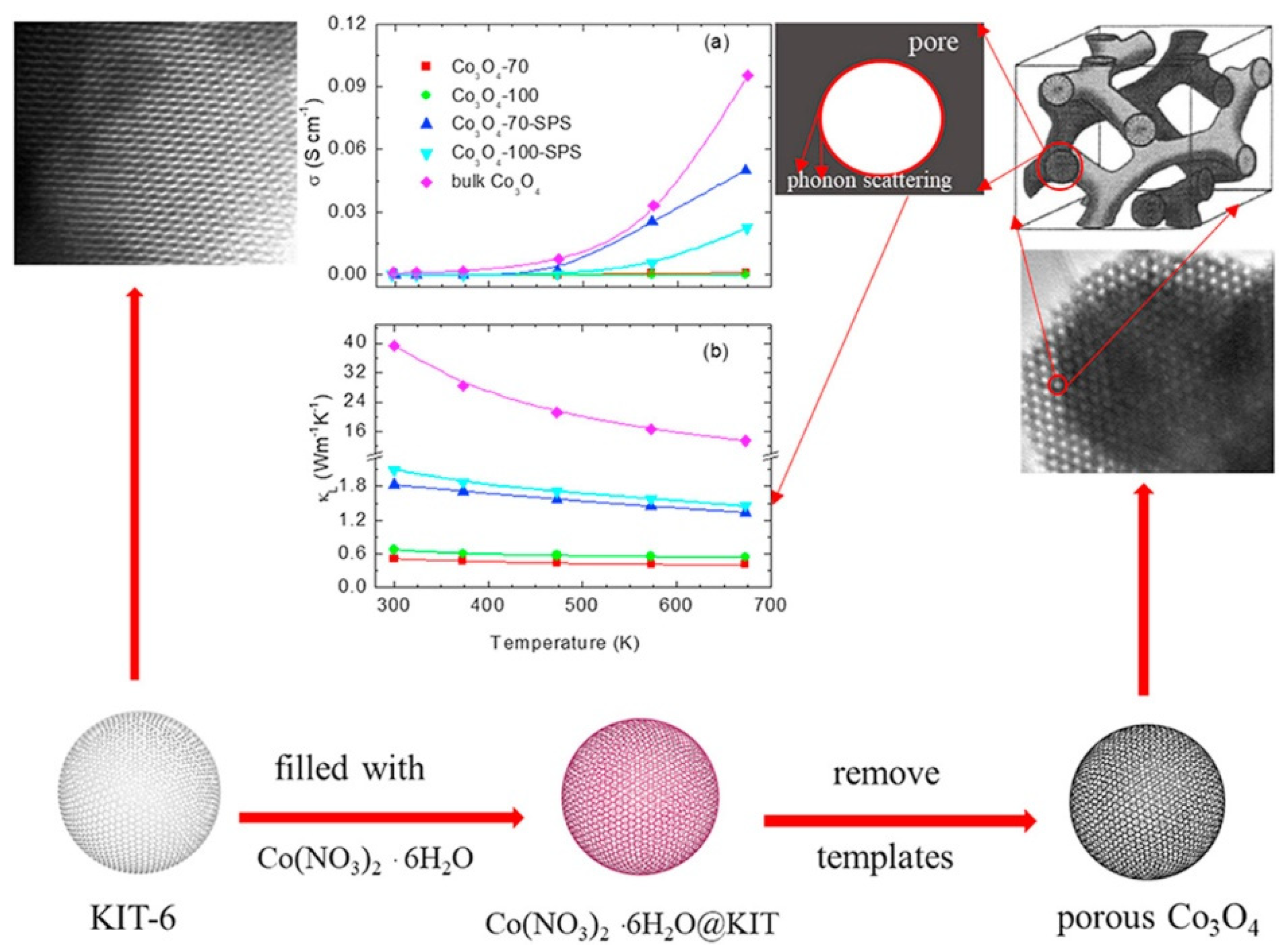
Chen et al. [92] used the nanocasting technique to prepare cobalt oxide nanostructures. The hard template: silica, was made from an ordered polymeric carbon replica. Significant reduction in the thermal conductivity of Co3O4 with ordered mesoporous structures was confirmed. Both nanocasting procedures by the use of the template (KIT-6) and the transport behavior of various cobalt oxide specimens are shown in Figure 7 [92]. The inset (a) represents the electrical conductivity change under different testing temperature conditions, and the inset (b) shows the thermal conductivity variation with the testing temperature. One of the cobalt oxide compound samples named Co3O4-70 shows the giant reduction in thermal conductivity, which is good for enhancing the thermoelectric figure of merit.
Procedures for synthesizing the hard template are described following the method as reported by Zhou et al. [93]. In brief, the amphiphilic triblock copolymer Pluronic (P-123) was dissolved in distilled water containing HCl. Following that, n-butanol was added. Then, this mixture was stirred for 1 h at 35 °C before tetraethyl orthosilicate (TEOS, C8H20O4Si) was added into the homogeneous clear solution. This mixture was further stirred at 35 °C for 24 h. After that, it was transferred into two stainless-steel autoclaves which were sealed and aged at two different temperatures (70 and 100 °C, respectively) for 24 h. The resulted mixtures were filtered several times. Being washed by water and air dried at 100 °C, the obtained powders were further calcined at 550 °C for 6 h in air to remove the carbon-based polymer residues. The produced mesoporous silica templates were subjected to aging at 70 and 100 °C and named as KIT-6-70 and KIT-6-100, respectively. It must be indicated that the Pluronic (P-123) is a symmetric linear triblock copolymer consisting of poly(ethylene oxide) (PEO) and poly(propylene oxide) (PPO) aligned in an alternating way, i.e., (PEO)x-(PPO)y-(PEO)z. The PPO block has a unique characteristic of showing hydrophobicity at temperatures above 15 °C and solubility in water at temperatures below 15 °C. This leads to the formation of micelle consisting of PEO-PPO-PEO triblock copolymers. The hydrophobic core contains PPO block, and the hydrophilic corona consists of PEO block. If the concentration of the P-123 in water is carefully controlled, the desired cubic gelation phase could be obtained. For example, a 30 wt.% aqueous solution of Pluronic P-123 allows the formation of a cubic gelation phase to hold the silica-based compound, tetraethyl orthosilicate, in its open space.
Then, the mesoporous Co3O4 was synthesized using the prepared KIT-6-70 or KIT-6-100 template [93]. As also shown in [94], the nitrate compound Co(NO3)2·6H2O was used as the precursor. The as-synthesized KIT-6-70 or KIT-6-100 was suspended in the linear chain liquid hexane or n-hexane. The cobalt nitrate aqueous solution was added dropwise under vigorous stirring. The mixture was continuous stirred until the n-hexane volatilized completely. After the mixture dried at room temperature overnight, a pink powder was obtained. The powder specimen was calcined at different temperatures such as 300, 500, and 550 °C for 5 h. The high temperature calcination caused the nitrate to decompose completely and was converted into cobalt oxide. The silica template was then removed by etching twice with 2.0 M warm NaOH aqueous solution for 12 h each time. The template-free mesoporous Co3O4 was collected by centrifugation. After that, it was washed with deionized water to neutral. The neutral powder was completely dried at 100 °C. This mesoporous Co3O4 prepared by nanocasting was used as the raw material for making thermoelectric specimens after the completion of various post processing and manufacturing processes. One of the processes was cold pressing into pellets at the room temperature under a pressure of 10 MPa for 10 min. Then the pellets were consolidated by spark plasma sintering (SPS) at 550 °C under a pressure of 100 MPa. In another case of post processing, the Co3O4 powder was directly spark plasma sintered. The samples from both post treatment processes were studied for thermoelectric energy conversion. Comparative study on the thermal conductive behavior of the bulk cobalt oxide and nanocast one was made as well. It is found that the bulk Co3O4 has the thermal conductivity as high as 39.3 W/(m∙K) at the room temperature [92]. While a typical nanocast Co3O4 sample shows the thermal conductivity as low as 0.51 W/(m∙K) as shown by the inset (b) in Figure 7 [92]. Such a dramatic reduction in the thermal conductivity should be very helpful for increasing the thermoelectric figure of merit, zT, of the Co3O4 material.

2.4. Solid-State Processing

Solid state processing has been widely used to make thermoelectric oxide materials [44,84,85,86,87,88,89,90,91,92,93,94,95,96,97,98]. Diez et al. [44] made the Ca3Co(4−x)CrxO9 polycrystalline thermoelectric oxide materials with small amounts of Cr. The solid-state processing method can be briefly summarized as follows, taking Ca3Co(4−x)CrxO9 (x = 0.00, 0.01, 0.03, 0.05, and 0.10) as examples as described in [44]. The polycrystalline oxide materials were made from the carbonate and oxide compounds such as CaCO3, Co2O3, and Cr2O3. Appropriate amount of each compound powder was weighed, well mixed, and ball milled in the acetone medium. The obtained slurry was heated using infrared radiation to remove the acetone. The dry mixture was milled again under dry condition to prevent any powder aggregations. Then, the mixture was heat treated twice in air at 750 and 800 °C, respectively, for 12 h. An intermediate manual milling was used to assist the decomposition of CaCO3. After the heat treatment, the powder mixture was pressed at 400 MPa shortly to generate green ceramic pellets. The pellets were further sintered at 900 °C for 24 h to form the specimens for thermoelectric property characterization.
It is convenient to introduce additives or dopants into the base Ca-Co-O oxide through the solid-state processing route. Presečnik and Bernik [96] doped the Ca3Co4O9 oxide with WO3 by directly adding WO3 powder as one of the starting materials. Without increasing the sintering temperature for consolidating the green ceramic specimen, the WO3-doped Ca3Co4O9 oxide with good quality was obtained. The Seebeck effect coefficient was found to increase slightly from 147 µV/K for the un-doped oxide to 157 µV/K for the doped specimen. In addition, the thermal conductivity is significantly decreased from 1.15 W/(m∙K) for the specimen without the WO3 dopant to 0.88 W/(m∙K) for the WO3-doped Ca3Co4O9 oxide. Kahraman et al. [97] doped the Ca3Co4O9 oxide with silver. Before the solid-state processing, a sol–gel procedure was adopted to make the slurry containing silver nitrate. The same sintering temperature of 900 °C was used to form the Ag-doped Ca3Co4O9 for the thermoelectric property evaluation. It is found that the thermoelectric power factor was increased due to the silver doping. PbO was introduced into Ca3Co4O9 through the solid-state processing as shown by Demirel et al. [98]. With the Pb-ion doping, the Seebeck effect coefficient of the specimen was increased to 200 µV/K. The thermoelectric figure of merit, zT value for the Pb-doped specimen is about 16 times higher than that for the specimen without any Pb doping.
A modified solid-state processing method is shown in [47] by introducing pressure-assisted sintering (PAS). During high temperature sintering, a pressure was added to the specimen to increase the density of the Ca3Co4O9 material. Better results were achieved by the PAS calcined sample. The dense and textured microstructure generated by PAS allows a high-power factor of 326 μW/(m∙K2) at 800 °C. However, the adverse effect in view of the increase in thermal conductivity remains to be resolved.
Still another derived solid-state processing is mechanical exfoliation or peeling of bulk materials to form thin coatings. Although it is famous for making graphene, other low dimensional materials, for example, a p-type two dimensional BiOBr thermoelectric oxide as mentioned in [99] was also made by this approach.
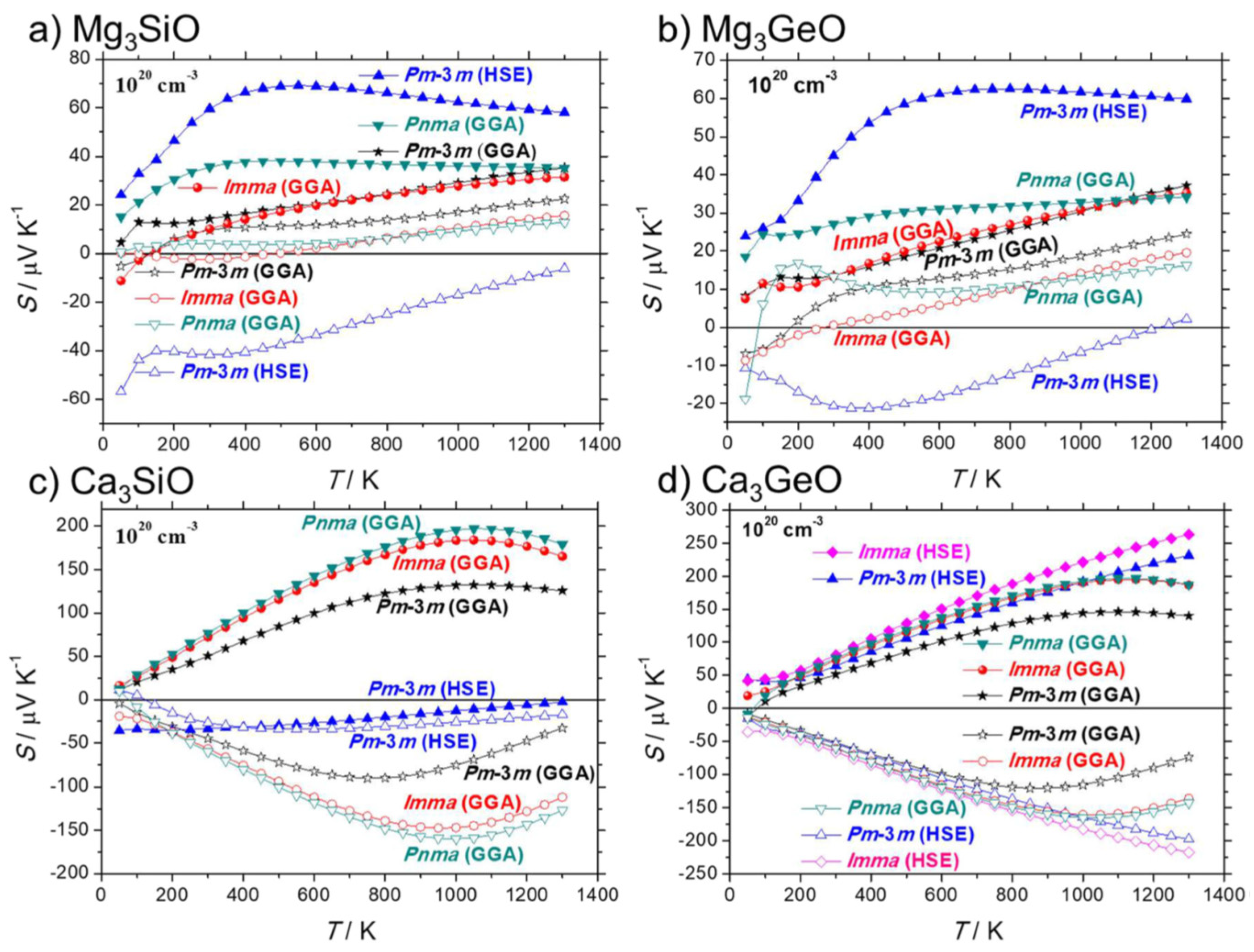
Inverse perovskites, Mg3SiO and Mg3GeO, Ca3SiO and Ca3GeO are considered as promising thermoelectric oxide materials with good performance as indicated by the computational results [100]. The computed Seebeck coefficients are shown in Figure 8 for four types of inverse perovskites. The Boltzmann equations with a relaxation time limited by acoustic phonon scattering and a carrier concentration of 1020 cm−3 were used for the computation. Ca3SiO and Ca3GeO are caught particular interest. These two oxides were experimentally processed via solid-state reactions. In brief, the starting materials including Ca granules, Si powder, and SiO2 powder for Ca3SiO preparation; Ca granules, Ge ingot, and GeO2 powder for Ca3GeO formation were mixed, respectively, in an Ar-filled glovebox. To produce Ca3SiO and Ca3GeO, the two different mixtures were placed in separated niobium tubes that were sealed by welding in Ar atmosphere. Each of the Nb tubes was inserted into a fused-silica tube. The silica tubes were then evacuated and sealed. To complete the solid-state reactions, the two mixtures were heated up to 1423 K over 11 h and kept at the temperature for 4 days. Then, the generated products were cooled down slowly at a rate of 3 K/min to 1073 K. After that, they were kept at the temperature (1073 K) for 2 days. Finally, they were cooled down to the room temperature over 8 h. The obtained samples are gray powders that are moisture- and air-sensitive. The powder samples were cold-pressed into Ca3SiO and Ca3GeO pellets. The consolidated pellets were adhered between two gold-plated copper disks with silver epoxy. The electrical resistivity and the thermal conductivity were determined from the electrical resistance and the thermal conductance, respectively. The thermal conductivity was corrected assuming an emissivity of one due to blackbody radiation. The Seebeck coefficient was calculated from the voltage drop by applying a temperature gradient. Figure 9 shows the measured results of electrical resistivity, Seebeck coefficient, and thermal conductivity of the Ca3SiO and Ca3GeO specimens. It can be seen from the experimental results that these inverse perovskites demonstrate high Seebeck coefficients and low thermal conductivities. Both Ca3SiO and Ca3GeO have potential for practical thermoelectric applications.
In order to prepare the precursors for solid state processing, a solution-based method followed by self-propagating combustion was adopted in the work performed by Madre et al. [101]. First, synthesis of Bi-Sr-Co-O precursors was carried out by making an acetic solution using glacial acetic acid and metallic acetates as the starting materials. Then, polyethyleneimine (PEI) was added (with the mole ratio of PEI to Bi2Sr2Co1.8Ox = 1:2) into the solution, resulting in the cation-nitrogen coordination. After air dried, a dark pink thermoplastic paste was obtained. The mixture was baked at 50 °C to change into violet color. Then it was heated up to 300 to 350 °C to initiate the self-propagating combustion. The combustion allowed the temperature to go up to 750 °C. The dark powder product was collected for the subsequent solid-state processing including pulverizing, pressing and sintering.
Sotelo et al. [102] synthesized the Bi2Ca2Co1.7Ox based thermoelectric oxide by different methods including the solid-state route, sol-gel synthesis, and the polymer approach. In the solid-state processing, Bi2O3, CaCO3, and Co3O4 were ball-milled first. Then the mixture was heat treated at 750 °C for 12 h. After that, the powder was cooled down and grounded. The grounded powder was heat treated again at 800 °C for 12 h. Then the powder was milled again and pressed at 250 MPa into pellets. Lastly, the pellets were sintered at 800 °C for 24 h to form the Bi2Ca2Co1.7Ox based thermoelectric oxide specimens. The sol–gel synthesis used nitrates to make slurry for self-propagating combustion. The obtained mixture was cold-pressed and sintered at the high temperature of 800 °C to get the Bi2Ca2Co1.7Ox. In the polymer approach, the process of cation-nitrogen coordination by polyethyleneimine (PEI) polymer was used as described in [102]. The preparation of the final product (Bi2Ca2Co1.7Ox) also relies on the solid-state processing. Comparative studies of the three synthesis routes revealed that the solid-state method resulted in a fairly good Bi2Ca2Co1.7Ox product. However, the sol–gel method allowed much higher yields of the cobaltite phase. Therefore, improved thermoelectric properties were observed. The polymer-based route was considered as the best way regarding to the structural homogeneity and enhanced zT value. The increase in the zT value was believed due to the reduction of secondary phases, the complexity of grain shape, and the high oxygen vacancies generated through the polymer approach.

2.5. Energy Beam Techniques

Energy beam techniques include plasma deposition, electron beam (e-beam or EB) processing, ion-beam injection/deposition, pulsed laser deposition (PLD), and laser-assisted catalytic growth. The bombardment of energy beams vaporizes materials from targets. The vaporized materials subsequently deposit on substrates. The facilities for energy beam-assisted processing typically include a beam source and all the other components as found for vapor deposition [72,103]. The target materials could be pure metals, metallic alloys, polymers, and ceramics [104]. Sometimes more than one target may be used simultaneously to deposit multilayered complex coatings. For example, Jones et al. [104] deposited layered oxide materials having alternating repeated layer thicknesses of 10 nm or less. Such complex and fine structures with sharp interfaces are usually hard to fabricate. Nanostructured oxide thin films with repeated layers of two different oxide materials were generated by pulsed-laser deposition during which two independent stationary targets consisting of Al2O3 and BaTiO3 were used [104]. The deposition rate of PLD varies with the types of beam, atmosphere in the chamber, temperature of the substrate, the magnitude of the laser power, and the oxygen background gas pressure level in the chamber [105].
Among various energy beam techniques, pulsed laser deposition is considered as a powerful tool. Pulsed laser deposition (PLD) is classified as one of the physical vapor deposition (PVD) techniques. Inside a vacuum chamber, a high-power and pulsed-laser beam bombasts a target of the material that is to be deposited. The material sublimates from the target in a plasma plume and deposits as a thin layer of coating on a substrate. The substrate may be a silicon wafer or a ceramic plate facing the target [106]. This process can be done in ultra-high vacuum or in the presence of a background gas, such as oxygen which is commonly used when depositing oxides to fully oxygenate the deposited coatings. Hydrogen and argon gases may also be used for LPD [107].
The physical phenomena of laser-target interaction and film growth are quite complex. When the laser pulse is absorbed by the target, energy is first converted to electronic excitation and then into thermal, chemical, and mechanical energy resulting in evaporation, ablation, plasma formation, and even exfoliation. The ejected species expand into the surrounding vacuum in the form of a plume containing many energetic species including atoms, molecules, electrons, ions, clusters, particulates and molten globules, before depositing on the typically hot substrate [108].
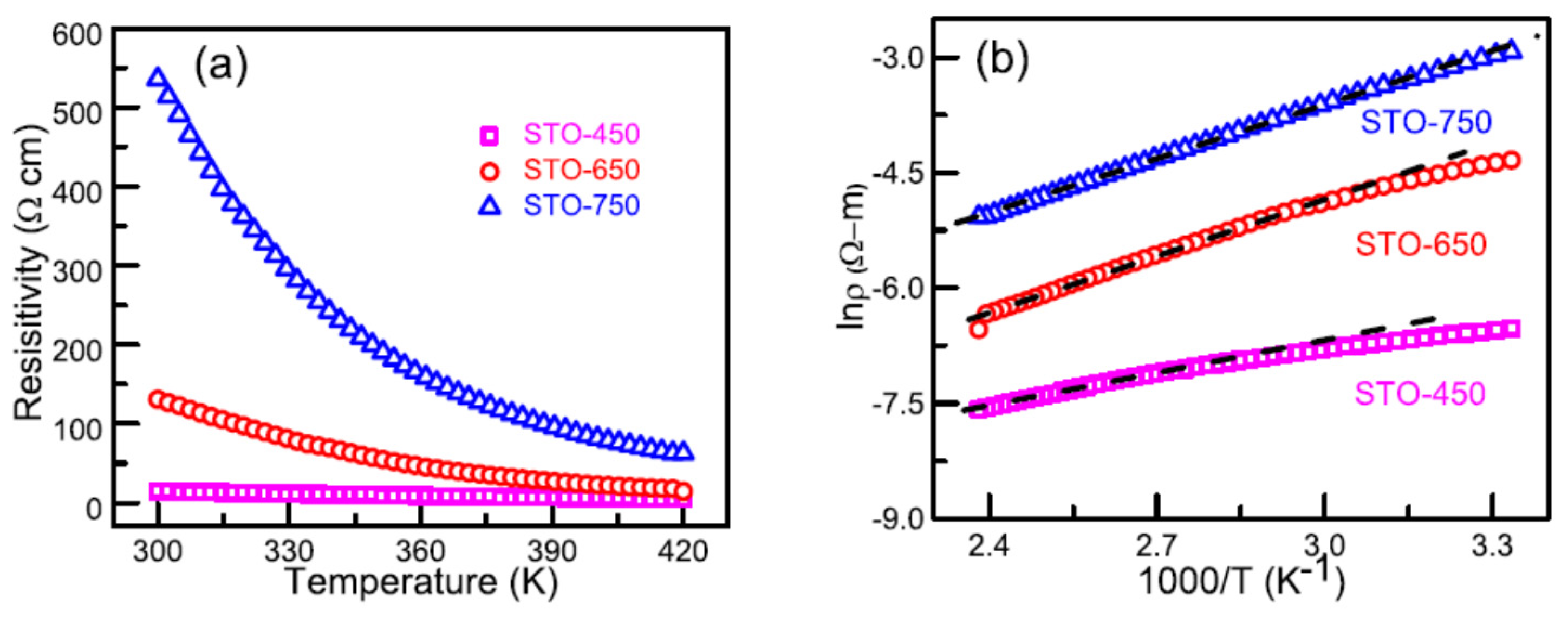
SrTiO3 coatings were prepared by pulsed laser deposition (PLD) [109,110]. Following the PLD, nitrogen ion implantation with the energy level of 60 keV was carried out. Structure and transport behavior of the thin coatings were investigated. The local distortion of TiO6 octahedra and introduction of oxygen vacancies due to N implantation were confirmed by the X-ray absorption spectroscopy of the films. The temperature-dependent electrical and thermoelectric properties of these coatings were evaluated to understand the conduction and scattering mechanisms. Both electrical conductivity and Seebeck coefficient of these SrTiO3 thin films were significantly enhanced at high dosage of N ion implantation. The effect of temperature on the electrical resistivity was examined in the temperature range from 80 to 400 K. Various conduction mechanisms were proposed to analyze the electrically conductive behavior. Data fitting with band conduction, near neighbor hopping (NNH), and variable range hopping (VRH) models was performed. It is found that the band conduction mechanism dominates in both high temperature regime and low temperature regime. The crossover between NNH and VRH was observed as well. The Seebeck coefficient, S, was estimated using the relaxation time approximation model and dispersive transport mechanism in the temperature range from 300 to 400 K. It is revealed that the ion beam implantation enhances the electrical conductivity and thermopower of the coatings. The power factor is as high as 15 µW/(m∙K2) at 400 K, which is much higher than that of the pristine SrTiO3 coatings. It is evident that the energy beam processing can improve the electrical transport properties of thermoelectric oxide coatings. The temperature-dependent electrical resistivity, ρ, of STO processed via PLD at 450, 650, and 750 °C (samples named as STO-450, STO-650, and STO-750) is shown in Figure 10a [110]. In Figure 10b, the logarithm of electrical resistivity is presented. From the results shown in Figure 10b, linear relations are revealed. This indicated that the STO samples of the conduction mechanism follow the thermally activated charge carriers, jumping from the localized states to the conduction band.
Electron beam irradiation changed the electrical transport properties of a polycrystalline PrCoO3 thermoelectric oxide in a different way as shown in [111]. The polycrystalline bulk samples of cobaltite PrCoO3 were irradiated by electron beam (EB) at room temperature for various dosages of 50, 100, and 200 kGy. A linear particle accelerator was used to carry out the EB irradiation. The beam energy of the used linear accelerator was 7.5 MeV under the beam power of 1.5 kW. Unlike the case for STO after ion beam implantation [109], the EB irradiation reduced the Seebeck coefficient of the PrCoO3 dramatically. The reason for this is that EB irradiation hinders the phonon drag.
Ion beam sputtering (IBS) is also called ion beam deposition (IBD) or ion beam sputtering deposition (IBSD). It is a thin coating deposition process that uses an ion source to deposit or sputter a target material (metal or dielectric) onto a substrate to create either a metallic or dielectric coating. Kennedy et al. [112] demonstrated that the ion beam method is a suitable approach to enhancing the thermoelectric properties of Al-doped ZnO coatings. Comparative studies on the electrical and thermoelectric properties of un-doped and Al-doped zinc oxide (ZnO) thin coatings were performed. The Al doping was carried out using 25 keV aluminum ion implantation. The doped concentration of aluminum into ZnO reached 0.1%, 1%, and 2%, respectively. From X-ray diffraction measurements, it is found that the lattice parameters of the doped coatings are larger than those of the values for bulk zinc oxide, indicating the incorporation of Al atoms at the interstitial sites. Al doping increased the electrical conductivity from 100 (S/cm) for the un-doped ZnO coating to 598 (S/cm) for the 2% Al doped film. Electron doping by Al resulted in an increase in the carrier concentration. The mobility of charge career reached the highest for the 2% Al-doped ZnO. The absolute value of the Seebeck coefficient increased from 61 µV/K for the un-doped to 66 µV/K for the 2% Al-doped film. Consequently, the power factor increased significantly from 2.58 × 10⁻⁵ W/(m∙K2) for the un-doped ZnO to 2.63 × 10⁻⁴ W/(m∙K2) for the 2% Al doped coating.
Ion beam sputtering deposition was used by Zhang et al. [113] to prepare thermoelectric indium tin oxide (ITO) coating with the potential for thermal couple application from room temperature to 1200 °C. The indium tin oxide (ITO) thin coating was directly deposited on an alumina substrate by ion beam sputtering from an ITO target with the composition of In2O3:SnO2 = 1:9 in weight. The initial vacuum level in ion beam sputtering chamber was about 5 × 10⁻⁴ Pa. During the ion beam sputtering, the chamber pressure was sustained at 2 × 10⁻² Pa. The energy level of the ion beam source was 0.9 keV. The electrical current of the ion source was 80 mA. The obtained ITO coating showed an average Seebeck coefficient of 65.39 µV/K. The thermal couple made by the ITO and Pt has stable thermoelectric outputs during both heating and cooling cycles.
Using the pulsed laser deposition (PLD) technique, Zhu et al. [114] prepared p-type Ca3Co4O9 (CCO) coatings on c-cut Al2O3 single crystal substrates via epitaxial growth. In addition, ion beam injection technique was used to inject different doses of Nb ions into the films. After that, annealing the specimens in pure nitrogen gas was conducted to allow a nanoscale NbNx secondary phase formation in the films. To obtain the power factor of the coatings, the resistivity and Seebeck coefficient of the coatings were measured in the temperature range from 175 to 375 K. The calculated power factor of the coatings was found to increase if appropriate amount of Nb was injected. When the injected Nb concentration was 1.46 × 10²⁰/cm3, the power factor of the coating, 0.17 mW/(m∙K2), was twice as large as that of the pure CCO coating. The maximum power factor of the Nb-ion injected coating reached 0.22 mW/(m∙K2) at 375 K.
Ion beam sputter deposition (IBSD) was also used to grow epitaxial oxide superlattice (SL) coatings consisting of Perovskite SrTiO3 (STO) and Nb-doped SrTiO3 (STNO) on LaAlO3 (LAO) (001) substrates [115]. The ion beam sputtering deposition (IBSD) system was installed with double electron cyclotron resonance (ECR) ion guns. The [(STO)x/(STNO)y]10 SL coatings grew epitaxially with the stacking sequences that x = 6 nm, y = 1–6 nm, and z = 10. z is the maintained periodicity. It is found that the morphology, structure, and properties of the superlattice coatings are strongly dependent on the STNO sublayer thickness (y). Highly strained SL coatings with two-dimensional growth mode are observed at smaller STNO sublayer thickness (y = 1 nm). With the increase of thickness y to a critical value of 4 nm, the SL coatings are strain-free and transformed to the three-dimensional growth mode. It is concluded that the combined ECR-IBSD is a versatile technique for the growth of high-quality oxide SL coatings.
By combining pulsed laser deposition and electron beam lithography, it is possible to process complex oxide coatings with predefined patterns. Complex oxide coatings have many promising attributes, including wide band gaps for high temperature semiconductors, ion conducting electrolytes in fuel cells, ferroelectricity, and ferromagnetism. Both thin and thick oxide coatings can be readily manufactured by such a combined technology and tested. Typically, those physically hard and chemically inert materials can not be easily fabricated by direct application of conventional methods. In order to improve the thermoelectric properties of the oxide coatings at small scales, there must first be a simple and effective means to obtain the desired structures. As shown in [116], the use of pulsed laser deposition at room temperature onto electron beam lithography defined patterns of polymethyl methacrylate (PMMA) photoresist, and the Nb-doped SrTiO3 coating was obtained. Following the photoresist liftoff procedure in organic solvents, a post heat treatment was carried out to crystallize the structure of the coating. The morphology of the coating was observed using both scanning electron microscopy and atomic force microscopy. Crystallinity and composition as determined by X-ray diffraction and photoelectron spectroscopy were shown. In addition, the Nb-doped SrTiO3 oxide coating obtained by this integrated technique has been investigated for high temperature thermoelectric energy conversion.
It is worth discussing a little bit more the electron beam technology especially for cases with reactive gases being introduced into the chamber for deposition. In Beke’s review [117], electron beam deposition of vanadium pentoxide was described in more detail. The electron beam deposition was compared with the commonly used PVD processes for coating lenses and filters with anti-reflection, scratch-resistant, or other functional coatings. However, the e-beam method is not equivalent to the PVD processes such as resistive thermal evaporation in the sense that a high energy electron beam is the energy source for heating. The electron beam is electromagnetically focused on the target material. The kinetic energy of the electrons is converted into thermal energy as the electron beam bombards the target surface. Thus, the temperature increases, leading to the sublimation or formation of a liquid melt with a substantial vapor pressure. Some incident electron energy is lost in the excitation of X-rays and secondary electron emission. Electron beam deposition offers the possibility of precise control of deposition rate and coating composition, excellent material utilization, and sequential and co-deposition configurations. It also provides a low-energy atom flux with minimum contamination. Very high deposition rates can be achieved with precise structural and morphological control. Another advantage is the relatively low costs compared with pulsed laser deposition (PLD) and ion beam injection techniques. Electron beam deposition of V2O5 was demonstrated by Ramana et al. [118,119]. The properties of the vanadium oxide coating were found highly dependent on the oxygen partial pressure and deposition temperature. The reported optical band gaps varied from 2.04 to 2.66 eV as a function of the oxygen partial pressure. The band gap values were found to be 2.50, 2.66, and 2.58 eV for films deposited at the ambient temperature, and 300 and 400 °C, respectively [120]. The coatings grown at the ambient temperature showed a homogeneous, uniform, and smooth texture, but are amorphous in nature. However, the coatings deposited at substrate temperatures higher than 200 °C illustrated the polycrystalline structure with the texture along c-axis. The color of the coatings changed from pale yellow to light brown, then to black corresponding to deposition at the ambient temperature, and 300 and 500 °C, respectively. It was revealed that nanocrystalline V2O5 thin coatings with a [1] preferred orientation and a crystalline grain size of 17.7 nm grew on amorphous glass substrates at temperatures as low as 300 °C. Increasing the substrate temperature to 400 °C resulted in polycrystalline coatings with an average grain size of 11.4 nm [120].

3. Perspectives and Conclusions

In summary, thermoelectric metallic oxide coatings are promising for high temperature thermoelectric energy conversion applications due to their high corrosion resistance. Several metallic oxide coatings with tuned structures are suitable for building energy converters and sensors due to their enhanced thermoelectric performances. These include the n-type SrTiO3, LaAlO3, La2CuO4, TiO2, and ZnO, and the p-type NaCo2O4, CuO/Cu2O, and Ca3Co4O9. In view of the processing and manufacturing technology for thermoelectric oxide coating preparation, the liquid phase deposition, chemical vapor deposition, and plasma enhanced deposition are fast and cost-effective techniques. However, physical vapor deposition and high energy beam processing lead to more uniform coating formation. The high temperature method, chemical spray pyrolysis, allows selected compounds to be converted into oxides. There are still many challenges and new fields to explore for thermoelectric oxide coating processing. One of the challenges is to establish the processing and the thermoelectric performance relation. Since the figure of merit of most currently available oxide coatings is not so high, understanding the processing–property relation can guide the preparation of new oxide coatings with enhanced thermoelectric properties. Another issue is the lack of thermoelectric data of oxide coatings. More measurement studies will help develop thermoelectric property data bank of oxide coatings and understand the relationships among the composition, processing, structure, and property of oxide coatings. Comparative studies on the thermoelectric behavior of oxide coatings with oxides as embedded isolated phases in dissimilar materials [121] should be performed. It is also necessary to develop new measurement techniques for determining the thermal, electrical, and thermoelectric parameters of metal oxide coatings with high precision.

Funding

This research received no external funding.

Institutional Review Board Statement

Not applicable.

Informed Consent Statement

Not applicable.

Conflicts of Interest

The author declares no conflict of interest.

References

  1. Klochko, N.P.; Klepikova, K.S.; Khrypunova, I.V.; Zhadan, D.O.; Petrushenko, S.I.; Kopach, V.R.; Dukarov, S.V.; Sukhov, V.M.; Kirichenko, M.V.; Khrypunova, A.L. Flexible thermoelectric module based on zinc oxide thin film grown via SILAR. Curr. Appl. Phys. 2021, 21, 121–133. [Google Scholar] [CrossRef]
  2. Kumar, A.; Sivaprahasam, D.; Thakur, A.D. Colossal Seebeck coefficient in Aurivillius phase-perovskite oxide composite. J. Alloys Compd. 2021, 853, 157001. [Google Scholar] [CrossRef]
  3. Zhu, L.; Chen, L.X.; Li, H.Q.; Li, D.; Yang, N.; Jiang, X.B.; Qiu, S.Z. Performance analysis of alkali metal thermoelectric converter and segmented thermoelectric generator hybrid system based on a comprehensive model. Appl. Thermal. Eng. 2021, 183, 116206. [Google Scholar] [CrossRef]
  4. Tian, X.X.; Asaadi, S.; Moria, H.; Kaood, A.; Pourhedayat, S.; Jermsittiparsert, K. Proposing tube-bundle arrangement of tubular thermoelectric module as a novel air cooler. Energy 2020, 208, 118428. [Google Scholar] [CrossRef]
  5. Gan, Y.X. Nanomaterials for Thermoelectric Devices, 1st ed.; Jenny Stanford Publishing: Singapore, 2018; pp. 6–8. [Google Scholar]
  6. Boulat, L.; Viennois, R.; Oliviero, E.; Dadras, M.; Fréty, N. Study of TaN and TaN-Ta-TaN thin films as diffusion barriers in CeFe4Sb12 skutterudite. J. Appl. Phys. 2019, 126, 125306. [Google Scholar] [CrossRef]
  7. Appel, O.; Zaharoni, T.; Breuer, G.; Beeri, O.; Gelbstein, Y. Thermoelectric properties of Ti0.3Zr0.35Hf0.35Ni1.005Sn Half-Heusler alloy. J. Appl. Phys. 2019, 126, 085110. [Google Scholar] [CrossRef]
  8. Zeier, W.G.; Schmitt, J.; Hautier, G.; Aydemir, U.; Gibbs, Z.M.; Felser, C.; Snyder, G.J. Engineering Half-Heusler thermoelectric materials using Zintl chemistry. Nat. Rev. Mater. 2016, 1, 16032. [Google Scholar] [CrossRef]
  9. Landmann, D.; Tang, Y.; Kunz, B.; Huber, R.; Widner, D.; Rickhaus, P.; Widmer, R.N.; Elsener, H.R.; Battaglia, C. Fabrication, characterization, and application-matched design of thermoelectric modules based on Half-Heusler FeNbSb and TiNiSn. J. Appl. Phys. 2019, 126, 085113. [Google Scholar] [CrossRef]
  10. Rogl, G.; Ghosh, S.; Wang, L.; Bursik, J.; Grytsiv, A.; Kerber, M.; Bauer, E.; Mallik, R.C.; Chen, X.Q.; Zehetbauer, M.; et al. Half-Heusler alloys: Enhancement of ZT after severe plastic deformation (ultra-low thermal conductivity). Acta Mater. 2020, 183, 285–300. [Google Scholar] [CrossRef]
  11. Gürth, M.; Rogl, G.; Romaka, V.V.; Grytsiv, A.; Bauer, E.; Rogl, P. Thermoelectric high ZT Half-Heusler alloys Ti1−xyZrxHfyNiSn. Acta Mater. 2016, 104, 210–222. [Google Scholar] [CrossRef]
  12. Tavassoli, A.; Failamani, F.; Grytsiv, A.; Rogl, G.; Heinrich, P.; Müller, H.; Bauer, E.; Zehetbauer, M.; Rogl, P. On the Half-Heusler compounds Nb1−x{Ti,Zr,Hf}xFeSb: Phase relations, thermoelectric properties at low and high temperature, and mechanical properties. Acta Mater. 2017, 135, 263–276. [Google Scholar] [CrossRef]
  13. Shi, Y.; Sturm, C.; Kleinke, H. Chalcogenides as thermoelectric materials. J. Solid State Chem. 2019, 270, 273–279. [Google Scholar] [CrossRef]
  14. Gelbstein, Y.; Dashevsky, Z.; Dariel, M.P. High performance n-type PbTe-based materials for thermoelectric applications. Phys. B 2005, 363, 196–205. [Google Scholar] [CrossRef]
  15. Guo, Q.; Assoud, A.; Kleinke, H. Improved bulk materials with thermoelectric figure-of-merit>1: Tl10−xSnxTe6 and Tl10−xPbxTe6. Adv. Energy Mater. 2014, 4, 1400348. [Google Scholar] [CrossRef]
  16. Zhao, L.D.; Chang, C.; Tan, G.; Kanatzidis, M.G. SnSe: A remarkable new thermoelectric material. Energy Environ. Sci. 2016, 9, 3044–3060. [Google Scholar] [CrossRef]
  17. Zhao, L.D.; Lo, S.H.; Zhang, Y.S.; Sun, H.; Tan, G.H.; Uher, C.; Wolverton, C.; Dravid, V.P.; Kanatzidis, M.G. Ultralow thermal conductivity and high thermoelectric figure of merit in SnSe crystals. Nature 2014, 508, 373–377. [Google Scholar] [CrossRef]
  18. Liu, H.; Shi, X.; Xu, F.; Zhang, L.; Zhang, W.; Chen, L.; Li, Q.; Uher, C.; Day, T.; Snyder, G.J. Copper ion liquid-like thermoelectrics. Nat. Mater. 2021, 11, 422–425. [Google Scholar] [CrossRef] [PubMed]
  19. Assoud, A.; Thomas, S.; Sutherland, B.; Zhang, H.; Tritt, T.M.; Kleinke, H. Thermoelectric properties of the new polytelluride Ba3Cu14−δTe12. Chem. Mater. 2006, 18, 3866–3872. [Google Scholar] [CrossRef]
  20. Shi, Y.X.; Assoud, A.; Sankar, C.R.; Kleinke, H. TlAg12Se7: A new pnp conduction switching material with extraordinarily low thermal conductivity. Chem. Mater. 2017, 29, 9565–9571. [Google Scholar] [CrossRef]
  21. Snedaker, M.L.; Zhang, Y.; Birkel, C.S.; Wang, H.; Day, T.; Shi, Y.; Ji, X.; Kraemer, S.; Mills, C.E.; Moosazadeh, A.; et al. Silicon-based thermoelectrics made from a boron-doped silicon dioxide nanocomposite. Chem. Mater. 2013, 25, 4867–4873. [Google Scholar] [CrossRef] [Green Version]
  22. Zhou, Y.; Hu, M. Record low thermal conductivity of polycrystalline Si nanowire: Breaking the Casimir limit by severe suppression of propagons. Nano Lett. 2016, 16, 6178–6187. [Google Scholar] [CrossRef] [PubMed]
  23. Ferrer-Argemi, L.; Yu, Z.; Lee, J. Effects of metal silicide inclusion interface and shape on thermal transport in silicon nanocomposites. J. Appl. Phys. 2019, 126, 035106. [Google Scholar] [CrossRef]
  24. Nakasawa, H.; Hayashi, K.; Takamatsu, T.; Miyazaki, Y. Lattice dynamics and lattice thermal conductivity of CrSi2 calculated from first principles and the phonon Boltzmann transport equation. J. Appl. Phys. 2019, 126, 025105. [Google Scholar] [CrossRef]
  25. Murphy-Armando, F. Enhancement of the electronic thermoelectric properties of bulk strained silicon-germanium alloys using the scattering relaxation times from first principles calculations. J. Appl. Phys. 2019, 126, 215103. [Google Scholar] [CrossRef] [Green Version]
  26. Antonov, A.; Ivanov, Y.; Konstantinov, P.; Kuznetsova, V.; Novikov, S.; Ovchinnikov, A.; Pshenay-Severin, D.; Burkov, A. Thermoelectric and galvanomagnetic properties of topologically non-trivial (Co-M)Si semimetals (M = Fe, Ni) at high temperatures. J. Appl. Phys. 2019, 126, 245103. [Google Scholar] [CrossRef]
  27. Khalil, M.; Moll, A.; Godfroy, M.; Letrouit-Lebranchu, A.; Villeroy, B.; Alleno, E.; Viennois, R.; Beaudhuin, M. Thermoelectric properties and stability of nanostructured chromium disilicide CrSi2. J. Appl. Phys. 2019, 126, 135103. [Google Scholar] [CrossRef]
  28. Nonoguchi, Y.; Tani, A.; Kitano, T.; Kawai, T. Enhanced thermoelectric properties of semiconducting carbon nanotube films by UV/ozone treatment. J. Appl. Phys. 2019, 126, 135108. [Google Scholar] [CrossRef]
  29. Kim, G.; Kim, S.W.; Rim, H.J.; Lee, H.; Kim, J.; Roh, J.W.; Kim, B.W.; Lee, K.H.; Lee, W. Improved trade-off between thermoelectric performance and mechanical reliability of Mg2Si by hybridization of few-layered reduced graphene oxides. Script. Mater. 2019, 162, 402–407. [Google Scholar] [CrossRef]
  30. Tan, X.; Liu, Y.C.; Liu, R.; Zhou, Z.F.; Liu, C.; Lan, J.L.; Zhang, Q.H.; Lin, Y.H.; Nan, C.W. Synergistical enhancement of thermoelectric properties in n-type Bi2O2Se by carrier engineering and hierarchical microstructure. Adv. Energy Mater. 2019, 9, 1900354. [Google Scholar] [CrossRef]
  31. Kenfaui, D.; Lenoir, B.; Chateigner, D.; Ouladdiaf, B.; Gomina, M.; Noudem, J.G. Development of multilayer textured Ca3Co4O9 materials for thermoelectric generators: Influence of the anisotropy on the transport properties. J. Eur. Ceram. Soc. 2012, 32, 2405–2414. [Google Scholar] [CrossRef]
  32. Yin, Y.; Tudu, B.; Tiwari, A. Recent advances in oxide thermoelectric materials and modules. Vacuum 2017, 146, 356–374. [Google Scholar] [CrossRef]
  33. Baranovskiy, A.; Amouyal, Y. Structural stability of calcium-manganate based CaO(CaMnO3)m (m = 1, 2, 3, ∞) compounds for thermoelectric applications. J. Alloys Compd. 2016, 687, 562–569. [Google Scholar] [CrossRef]
  34. Tauc, J. The thermal photo-electric phenomenon in semi-conductors. Cechoslov. Fiz. Zurnal (Czechoslov. J. Phys.) 1955, 5, 528–535. [Google Scholar] [CrossRef]
  35. Kwok, H.B.; Bube, R.H. Thermoelectric and photothermoelectric effects in semiconductors: CdS single crystals. J. Appl. Phys. 1973, 44, 138. [Google Scholar] [CrossRef]
  36. Harper, J.G.; Matthews, H.E.; Bube, R.H. Photothermoelectric Effects in semiconductors: N- and p-type silicon. J. Appl. Phys. 1970, 41, 765. [Google Scholar] [CrossRef]
  37. Shiraishi, Y.; Tanabe, K.; Taniguchi, H.; Okazaki, R.; Terasaki, I. Interplay between quantum paraelectricity and thermoelectricity in the photo-Seebeck effect in a single crystal. J. Appl. Phys. 2019, 126, 045111. [Google Scholar] [CrossRef]
  38. Okazaki, R.; Horikawa, A.; Yasui, Y.; Terasaki, I. Photo-Seebeck effect in ZnO. J. Phys. Soc. Jpn. 2012, 81, 114722. [Google Scholar] [CrossRef] [Green Version]
  39. Horikawa, A.; Igarashi, T.; Terasaki, I.; Okazaki, R. Photo-Seebeck effect in polycrystalline ZnO. J. Appl. Phys. 2015, 118, 095101. [Google Scholar] [CrossRef]
  40. Tanabe, K. Influence of carrier diffusion on photo-Seebeck effect in zinc oxide. J. Appl. Phys. 2018, 124, 035108. [Google Scholar] [CrossRef]
  41. Suzuki, K.; Watanabe, T.; Kakemoto, H.; Irie, H. Photo- and gas-tuned, reversible thermoelectric properties and anomalous photo-thermoelectric effects of platinum-loaded tungsten trioxide. J. Appl. Phys. 2016, 119, 245109. [Google Scholar] [CrossRef]
  42. Azuma, C.; Kawano, T.; Kakemoto, H.; Irie, H. Photo-controllable thermoelectric properties with reversibility and photo-thermoelectric effects of tungsten trioxide accompanied by its photochromic phenomenon. J. Appl. Phys. 2014, 116, 173502. [Google Scholar] [CrossRef]
  43. Mondal, P.S.; Okazaki, R.; Taniguchi, H.; Terasaki, I. Photo-Seebeck effect in tetragonal PbO single crystals. J. Appl. Phys. 2013, 114, 173710. [Google Scholar] [CrossRef] [Green Version]
  44. Diez, J.C.; Torres, M.A.; Rasekh, S.; Constantinescu, G.; Madre, M.A.; Sotelo, A. Enhancement of Ca3Co4O9 thermoelectric properties by Cr for Co substitution. Ceram. Int. 2013, 39, 6051–6056. [Google Scholar] [CrossRef] [Green Version]
  45. Liu, J.; Wang, J.; Wang, C.; Xia, S. Ce1−xSrxZnSbO: New thermoelectric materials formed between intermetallics and oxides. J. Alloys Compd. 2016, 688, 849–853. [Google Scholar] [CrossRef]
  46. Zhang, Y.; Sugo, K.; Cho, H.J.; Ohta, H. Thermoelectric phase diagram of the SrTiO3-LaTiO3 solid-solution system through a metal to Mott insulator transition. J. Appl. Phys. 2019, 126, 075104. [Google Scholar] [CrossRef]
  47. Bresch, S.; Mieller, B.; Schoenauer-Kamin, D.; Moos, R.; Giovanelli, F.; Rabe, T. Influence of pressure assisted sintering and reaction sintering on microstructure and thermoelectric properties of bi-doped and undoped calcium cobaltite. J. Appl. Phys. 2019, 126, 075102. [Google Scholar] [CrossRef]
  48. Jerič, M.; de Boor, J.; Jančar, B.; Ceh, M. An enhanced thermoelectric figure of merit for Sr(Ti0.8Nb0.2)O3 based on a Ruddlesden–Popper-polytype-induced microstructure. J. Eur. Ceram. Soc. 2016, 36, 1177–1182. [Google Scholar] [CrossRef]
  49. Han, J.; Sun, Q.; Li, W.; Song, Y. Microstructure and thermoelectric properties of La0.1Dy0.1SrxTiO3 ceramics. Ceram. Int. 2017, 43, 5557–5563. [Google Scholar] [CrossRef]
  50. Tiginyanu, I.M.; Lupan, O.; Ursaki, V.V.; Chow, L.; Enachi, M. Nanostructures of metal oxides. In Comprehensive Semiconductor Science and Technology; Bhattacharya, P., Fornari, R., Kamimura, H., Eds.; Elsevier B.V.: Amsterdam, The Netherlands, 2011; Volume 3, pp. 396–479. [Google Scholar]
  51. Matsuo, J.; Katsumata, H.; Minami, E.; Yamada, I. O2 cluster ion-assisted deposition for tin-doped indium oxide films. Nucl. Instrum. Methods Phys. Res. Sec. B Beam Interact. Mater. At. 2000, 161–163, 952–957. [Google Scholar] [CrossRef]
  52. Therese, G.H.A.; Kamath, P.V. Electrochemical synthesis of metal oxides and hydroxides. Chem. Mater. 2000, 12, 1195–1204. [Google Scholar] [CrossRef]
  53. Esposito, S. “Traditional” sol-gel chemistry as a powerful tool for the preparation of supported metal and metal oxide catalysts. Materials 2019, 12, 668. [Google Scholar] [CrossRef] [PubMed] [Green Version]
  54. Zhang, H.; Ning, H.; Busbee, J.; Shen, Z.; Kiggins, C.; Hua, Y.; Eaves, J.; Davis III, J.; Shi, T.; Shao, Y.T.; et al. Electroplating lithium transition metal oxides. Sci. Adv. 2017, 3, e1602427. [Google Scholar] [CrossRef] [PubMed] [Green Version]
  55. Liu, Z.; Guo, R.; Meng, J.; Liu, X.; Wang, X.; Li, Q.; Mai, L. Facile electrospinning formation of carbon-confined metal oxide cube-in-tube nanostructures for stable lithium storage. Chem. Commun. 2017, 53, 8284–8287. [Google Scholar] [CrossRef] [PubMed]
  56. Tsukuma, K.; Akiyama, T.; Imai, H. Liquid phase deposition film of tin oxide. J. Non Cryst. Solids 1997, 210, 48–54. [Google Scholar] [CrossRef]
  57. Deng, X.; Chen, K.; Tüysüz, H. Protocol for the nanocasting method: Preparation of ordered mesoporous metal oxides. Chem. Mater. 2017, 29, 40–52. [Google Scholar] [CrossRef]
  58. Ozegowski, M.; Meteva, K.; Metev, S.; Sepold, G. Pulsed laser deposition of multicomponent metal and oxide films. Appl. Surf. Sci. 1999, 138–139, 68–74. [Google Scholar] [CrossRef]
  59. Kathalingam, A.; Shanmugam, K.; Park, H.C.; Kim, H.S. Fabrication of arrayed metal oxide structures by electrochemical local oxidation using metallic tip with electric field and humidity. J. Mater. Proc. Technol. 2018, 252, 304–312. [Google Scholar] [CrossRef]
  60. Hsu, M.C.; Leu, I.C.; Sun, Y.M.; Hon, M.H. Fabrication of CdS@TiO2 coaxial composite nanocables arrays by liquid-phase deposition. J. Cryst. Growth 2005, 285, 642–648. [Google Scholar] [CrossRef]
  61. Wu, J.M.; Wu, W.T.; Shih, H.C. Characterization of single-crystalline TiO2 nanowires grown by thermal evaporation. J. Electrochem. Soc. 2005, 152, G613. [Google Scholar] [CrossRef]
  62. Wang, Z.L. Functional oxide nanobelts: Materials, properties and potential applications in nanosystems and biotechnology. Annu. Rev. Phys. Chem. 2004, 55, 159–196. [Google Scholar] [CrossRef] [Green Version]
  63. Zhao, S.; Wang, L.; Yang, L.; Chen, Y. Synthesis and ultraviolet luminescence properties of half-wall Al2O3 nanotube arrays. J. Phys. D Appl. Phys. 2009, 42, 225106. [Google Scholar] [CrossRef]
  64. Li, P.G.; Lei, M.; Tang, W.H.; Guo, X.; Wang, X. Facile route to straight SnO2 nanowires and their optical properties. J. Alloys Compd. 2009, 477, 515–518. [Google Scholar] [CrossRef]
  65. Jiang, X.; Herricks, T.; Xia, Y. CuO nanowires can be synthesized by heating copper substrates in air. Nano Lett. 2002, 2, 1333–1338. [Google Scholar] [CrossRef]
  66. Xiang, X.; Cao, C.B.; Guo, Y.; Zhu, H.S. A simple method to synthesize gallium oxide nanosheets and nanobelts. Chem. Phys. Lett. 2003, 378, 660. [Google Scholar] [CrossRef]
  67. Cha, H.G.; Kim, C.W.; Kim, Y.H.; Jung, M.H.; Ji, E.S.; Das, B.K.; Kim, J.C.; Kang, Y.S. Preparation and characterization of α-Fe2O3 nanorod-thin film by metal-organic chemical vapor deposition. Thin Solid Film. 2009, 517, 1853–1856. [Google Scholar] [CrossRef]
  68. Basharat, S.; Carmalt, C.J.; Barnett, S.A.; Tocher, D.A.; Davies, H.O. Aerosol assisted chemical vapor deposition of In2O3 films from Me3In and donor functionalized alcohols. Inorg. Chem. 2007, 46, 9473–9480. [Google Scholar] [CrossRef]
  69. Terasako, T.; Ohmae, K.; Yamane, M.; Shirakata, S. Carrier transport in undoped CdO films grown by atmospheric-pressure chemical vapor deposition. Thin Solid Film. 2014, 572, 20–27. [Google Scholar] [CrossRef]
  70. Stetsovych, V.; Pagliuca, F.; Dvořák, F.; Duchoň, T.; Vorokhta, M.; Aulická, M.; Lachnitt, J.; Schernich, S.; Matolínová, I.; Veltruská, K.; et al. Epitaxial cubic Ce2O3 films via Ce-CeO2 interfacial reaction. J. Phys. Chem. Lett. 2013, 4, 866–871. [Google Scholar] [CrossRef]
  71. Ahmoum, H.; Li, G.J.; Belakry, S.; Boughrara, M.; Suait, M.S.; Kerouad, M.; Wang, Q. Structural, morphological and transport properties of Ni doped ZnO thin films deposited by thermal co-evaporation method. Mater. Sci. Semicond. Proc. 2021, 123, 105530. [Google Scholar] [CrossRef]
  72. Baptista, A.; Silva, F.; Porteiro, J.; Míguez, J.; Pinto, G. Sputtering physical vapour deposition (PVD) coatings: A critical review on process improvement and market trend demands. Coatings 2018, 8, 402. [Google Scholar] [CrossRef] [Green Version]
  73. Perednis, D.; Gauckler, L.J. Thin film deposition using spray pyrolysis. J. Electroceram. 2005, 14, 103–111. [Google Scholar] [CrossRef]
  74. Arca, E.; Fleischer, K.; Shvets, I.V. Influence of the precursors and chemical composition of the solution on the properties of ZnO thin films grown by spray pyrolysis. J. Phys. Chem. C 2009, 113, 21074–21081. [Google Scholar] [CrossRef]
  75. Hateef, A.A. Effect of the thickness on electrical properties of TiO2 thin films, prepared by thermal chemical spray pyrolysis deposition. Int. J. Innov. Res. Sci. Eng. Technol. (Irjesti) 2012, 1, 175–179. [Google Scholar]
  76. Andronic, L.; Manolache, S.; Duta, A. TiO2 thin films prepared by spray pyrolysis deposition (SPD) and their photocatalytic activities. J. Optoelectron. Adv. Mater. 2007, 9, 1403–1406. [Google Scholar]
  77. Boyadzhiev, S.; Georgieva, V.; Rassovska, M. Characterization of reactive sputtered TiO2 thin films for gas sensor applications. J. Phys. Conf. Ser. 2010, 253, 012040. [Google Scholar] [CrossRef]
  78. Hussian, H.A.R.A.; Hassan, M.A.M.; Agool, I.R. Synthesis of titanium dioxide (TiO2) nanofiber and nanotube using different chemical method. Optik 2016, 127, 2996–2999. [Google Scholar] [CrossRef]
  79. Ennaceri, H.; Boujnah, M.; Taleb, A.; Khaldoun, A.; Sáez-Araoz, R.; Ennaoui, A.; Kenz, A.E.; Benyoussef, A. Thickness effect on the optical properties of TiO2-anatase thin films prepared by ultrasonic spray pyrolysis: Experimental and ab initio study. Int. J. Hydrog. Energy 2017, 42, 19467–19480. [Google Scholar] [CrossRef]
  80. Oja, I.; Mere, A.; Krunks, M.; Solterbeck, C.H.; Es-Souni, M. Properties of TiO2 films prepared by the spray pyrolysis method. In Functional Nanomaterials for Optoelectronics and Other Applications; Lojkowski, W., Blizzard, J.R., Eds.; Solid State Phenom; Trans Tech Publications Ltd.: Stafa-Zurich, Switzerland, 2004; Volume 99–100, pp. 259–264. [Google Scholar] [CrossRef]
  81. Castaneda, L.; Alonso, J.C.; Ortiz, A.; Andrade, E.; Saniger, J.M.; Banuelos, J.G. Spray pyrolysis deposition and characterization of titanium oxide thin films. Mater. Chem. Phys. 2003, 77, 938–944. [Google Scholar] [CrossRef]
  82. Vautey, C.; Burgos, M.; Langlet, M. Aerosol-gel deposition and low temperature heat-treatment of SiO2 layers. Thin Solid Film. 1999, 347, 184–194. [Google Scholar] [CrossRef]
  83. Djaoued, Y.; Taj, R.; Brüning, R.; Badilescu, S.; Ashrit, P.V.; Bader, G.; Vo-Van, T. Study of the phase transition and the thermal nitridation of nanocrystalline sol–gel titania films. J. Non Cryst. Solids 2002, 297, 55–66. [Google Scholar] [CrossRef]
  84. Burgos, M.; Langlet, M. The sol-gel transformation of TIPT coatings: A FTIR study. Thin Solid Film. 1999, 349, 19–23. [Google Scholar] [CrossRef]
  85. Alam, M.J.; Cameron, D.C. Preparation and characterization of TiO2 thin films by sol-gel method. J. Sol Gel Sci. Technol. 2002, 25, 137–145. [Google Scholar] [CrossRef]
  86. Yao, T.; Uchimoto, Y.; Sugiyama, T.; Nagai, Y. Synthesis of (La, Sr)MeO3 (Me = Cr, Mn, Fe, Co) solid solutions from aqueous solutions. Solid State Ion. 2000, 135, 359–364. [Google Scholar] [CrossRef]
  87. Deki, S.; Iizuka, S.; Akamatsu, K.; Mizuhata, M.; Kajinami, A. Novel fabrication method for Si1−xTixO2 thin films with graded composition profiles by liquid phase deposition. J. Mater. Chem. 2001, 11, 984–986. [Google Scholar] [CrossRef]
  88. Koumoto, K.; Seo, S.; Sugiyama, T.; Seo, W.S.; Dressick, W.J. Micropatterning of titanium dioxide on self-assembled monolayers using a liquid-phase deposition process. Chem. Mater. 1999, 11, 2305–2309. [Google Scholar] [CrossRef]
  89. Deki, S.; Aoi, Y.; Asaoka, Y.; Kajinami, A.; Mizuhata, M. Preparation and characterization of Au-dispersed TiO2 thin films by a liquid-phase deposition method. J. Mater. Chem. 1996, 7, 733–736. [Google Scholar] [CrossRef]
  90. Gao, Y.; Masuda, Y.; Yonezawa, T.; Koumoto, K. Preparation of SrTiO3 thin films by the liquid phase deposition method. Mater. Sci. Eng. B 2003, 99, 290–293. [Google Scholar] [CrossRef]
  91. Su, L.; Gan, Y.X.; Zhang, L. Thermoelectricity of nanocomposites containing TiO2-CoO coaxial nanocables. Script. Mater. 2011, 64, 745–748. [Google Scholar] [CrossRef]
  92. Chen, L.L.; Zhang, Z.Y.; Qi, N.; Zhou, B.; Deng, S.P.; Chen, Z.Q.; Wu, Y.C.; Tang, X.F. Giant reduction in thermal conductivity of Co3O4 with ordered mesopore structures. Microporous Mesoporous Mater. 2020, 296, 109969. [Google Scholar] [CrossRef]
  93. Zhou, B.; Li, C.Y.; Qi, N.; Jiang, M.; Wang, B.; Chen, Z.Q. Pore structure of mesoporous silica (KIT-6) synthesized at different temperatures using positron as a nondestructive probe. Appl. Surf. Sci. 2018, 450, 31–37. [Google Scholar] [CrossRef]
  94. Sun, S.; Gao, Q.; Wang, H.; Zhu, J.; Guo, H. Influence of textural parameters on the catalytic behavior for CO oxidation over ordered mesoporous Co3O4. Appl. Catal. B Environ. 2010, 97, 284–291. [Google Scholar] [CrossRef]
  95. Jiang, D.; Ekren, D.; Azough, F.; Day, S.J.; Chen, K.; Mahajan, A.; Kepaptsoglou, D.M.; Ramasse, Q.M.; Reece, M.J.; Freer, R. The structure and thermoelectric properties of tungsten bronze Ba6Ti2Nb8O30. J. Appl. Phys. 2019, 126, 125115. [Google Scholar] [CrossRef] [Green Version]
  96. Presečnik, M.; Bernik, S. Microstructural and thermoelectric properties of WO3-doped Ca3Co4O9 ceramics. Ceram. Int. 2016, 42, 16103–16108. [Google Scholar] [CrossRef]
  97. Kahraman, F.; Madre, M.A.; Rasekh, S.; Salvador, C.; Bosque, P.; Torres, M.A.; Diez, J.C.; Sotelo, A. Enhancement of mechanical and thermoelectric properties of Ca3Co4O9 by Ag addition. J. Eur. Ceram. Soc. 2015, 35, 3835–3841. [Google Scholar] [CrossRef] [Green Version]
  98. Demirel, S.; Altin, E.; Oz, E.; Altin, S.; Bayri, A. An enhancement ZT and spin state transition of Ca3Co4O9 with Pb doping. J. Alloys Compd. 2015, 627, 430–437. [Google Scholar] [CrossRef]
  99. Yu, J.; Li, T.; Sun, Q. Single-layer BiOBr: An effective p-type 2D thermoelectric material. J. Appl. Phys. 2019, 125, 205111. [Google Scholar] [CrossRef]
  100. Pöhls, J.H.; Mar, A. Thermoelectric properties of inverse perovskites A3TtO (A = Mg, Ca; Tt = Si, Ge): Computational and experimental investigations. J. Appl. Phys. 2019, 126, 025110. [Google Scholar] [CrossRef]
  101. Madre, M.A.; Rasekh, S.; Diez, J.C.; Sotelo, A. New solution method to produce high performance thermoelectric ceramics: A case study of Bi-Sr-Co-O. Mater. Lett. 2010, 64, 2566–2568. [Google Scholar] [CrossRef] [Green Version]
  102. Sotelo, A.; Rasekh, S.; Madre, M.A.; Guilmeau, E.; Marinel, S.; Diez, J.C. Solution-based synthesis routes to thermoelectric Bi2Ca2Co1.7Ox. J. Eur. Ceram. Soc. 2011, 31, 1763–1769. [Google Scholar] [CrossRef] [Green Version]
  103. Griesser, A.; Kraus, T.; Klein, O.; Karl, H. Low-resistance electrical contact between epitaxially grown thermoelectric oxide material (Ca2CoO3)(0.62)CoO2 and iridium. Thin Solid Film. 2021, 717, 138420. [Google Scholar] [CrossRef]
  104. Jones, J.G.; Boeckl, J.J.; Smith, S.R.; Landis, G.R.; Murphy, N.R.; Hu, Z.Q.; Bowers, C.T.; Stutz, C.E. Al2O3-BaTiO3 nanolaminates fabricated by multistationary target pulsed laser deposition with in situ ellipsometry. J. Nanophotonics 2017, 11, 043506. [Google Scholar] [CrossRef]
  105. Gutierrez-Llorente, A.; Iglesias, L.; Rodriguez-Gonzalez, B.; Rivadulla, F. Epitaxial stabilization of pulsed laser deposited Srn+1IrnO3n+1 thin films: Entangled effect of growth dynamics and strain. APL Mater. 2018, 6, 091101. [Google Scholar] [CrossRef] [Green Version]
  106. Kulik, P.; Yu, C.J.; Sokolov, A.; Liang, W.T.; Harris, V.G. BaFe12O19 magnetoplumbite films grown on SiO2/Si substrates for widescale magnetic film semiconductor systems integration. Scr. Mater. 2020, 188, 190–194. [Google Scholar] [CrossRef]
  107. Xiao, T.T.; Yang, Q.; Yu, J.; Xiong, Z.W.; Wu, W.D. Annealing condition effects on the structural properties of FePt nanoparticles embedded in MgO via pulsed laser deposition. Nanomaterials 2021, 11, 131. [Google Scholar] [CrossRef] [PubMed]
  108. Cesaria, M.; Lorusso, A.; Caricato, A.P.; Finocchiaro, P.; Amaducci, S.; Martino, M.; Aziz, M.R.; Calcagnile, L.; Perrone, A.; Quarta, G. B-10-based films grown by pulsed laser deposition for neutron conversion applications. Appl. Phys. A Mater. Sci. Proc. 2020, 126, 404. [Google Scholar] [CrossRef]
  109. Bhogra, A.; Masarrat, A.; Meena, R.; Hasina, D.; Bala, M.; Dong, C.L.; Chen, C.L.; Kumar, T.A.; Kandasami, A. Tuning the electrical and thermoelectric properties of N ion implanted SrTiO3 thin films and their conduction mechanisms. Sci. Rep. 2019, 9, 14486. [Google Scholar] [CrossRef] [PubMed]
  110. Bhogra, A.; Masarrat, A.; Hasina, D.; Meena, R.; Umapathy, G.R.; Kumar, A.; Som, T.; Dong, C.L.; Chen, C.L.; Kandasami, A. Significant role of substrate temperature on the morphology, electronic structure and thermoelectric properties of SrTiO3 films deposited by pulsed laser deposition. Surf. Coat. Technol. 2021, 407, 126740. [Google Scholar] [CrossRef]
  111. Christopher, B.; Rao, A.; Deka, U.; Prasad, K.S.; Okram, G.S.; Sanjeev, G.; Petwal, V.C.; Verma, V.P.; Dwivedi, J. Electrical, thermal and magnetic studies on 7.5 MeV electron beam irradiated PrCoO3 polycrystalline samples. Phys. B Condens. Matter 2018, 540, 26–32. [Google Scholar] [CrossRef]
  112. Kennedy, J.; Murmu, P.P.; Leveneur, J.; Williams, G.V.W.; Moody, R.L.; Maity, T.; Chong, S.V. Enhanced power factor and increased conductivity of aluminum doped zinc oxide thin films for thermoelectric applications. J. Nanosci. Nanotechnol. 2018, 18, 1384–1387. [Google Scholar] [CrossRef]
  113. Zhang, Y.; Cheng, P.; Yu, K.Q.; Zhao, X.L.; Ding, G.F. ITO film prepared by ion beam sputtering and its application in high-temperature thermocouple. Vacuum 2017, 146, 31–34. [Google Scholar] [CrossRef]
  114. Zhu, C.H.; Li, Z.Z.; An, H.P.; Tang, G.D.; Hou, D.L. Enhancing the thermoelectric properties of Ca3Co4O9 thin films by the addition of a nanoscale NbNx second phase. J. Electron. Mater. 2014, 43, 3666–3671. [Google Scholar] [CrossRef]
  115. Panomsuwan, G.; Takai, O.; Saito, N. Fabrication and characterization of epitaxial SrTiO3/Nb-doped SrTiO3 superlattices by double ECR ion beam sputter deposition. Vacuum 2013, 89, 35–39. [Google Scholar] [CrossRef]
  116. Waller, G.; Stein, A.; Abiade, J.T. Nanofabrication of doped, complex oxides. J. Vac. Sci. Technol. B 2012, 30, 011804. [Google Scholar] [CrossRef]
  117. Beke, S. A review of the growth of V2O5 films from 1885 to 2010. Thin Solid Film 2011, 519, 1761–1771. [Google Scholar] [CrossRef]
  118. Ramana, C.V.; Hussain, O.M.; Naidu, B.S.; Reddy, P.J. Influence of substrate temperature on the composition and structural properties of electron beam evaporated V2O5 thin films. Vacuum 1997, 48, 431–434. [Google Scholar] [CrossRef]
  119. Ramana, C.V.; Hussain, O.M.; Uthanna, S.; Naidu, B.S. Influence of oxygen partial pressure on the optical properties of electron beam evaporated vanadium pentoxide thin films. Opt. Mater. 1998, 10, 101–107. [Google Scholar] [CrossRef]
  120. Kumar, A.; Singh, P.; Kulkarni, N.; Kaur, D. Structural and optical studies of nanocrystalline V2O5 thin films. Thin Solid Film 2008, 516, 912–918. [Google Scholar] [CrossRef]
  121. Gan, Y.X.; Gan, J.B. Measuring the electrical and photonic properties of cobalt oxide-containing composite carbon fibers. J. Compos. Sci. 2020, 4, 156. [Google Scholar] [CrossRef]
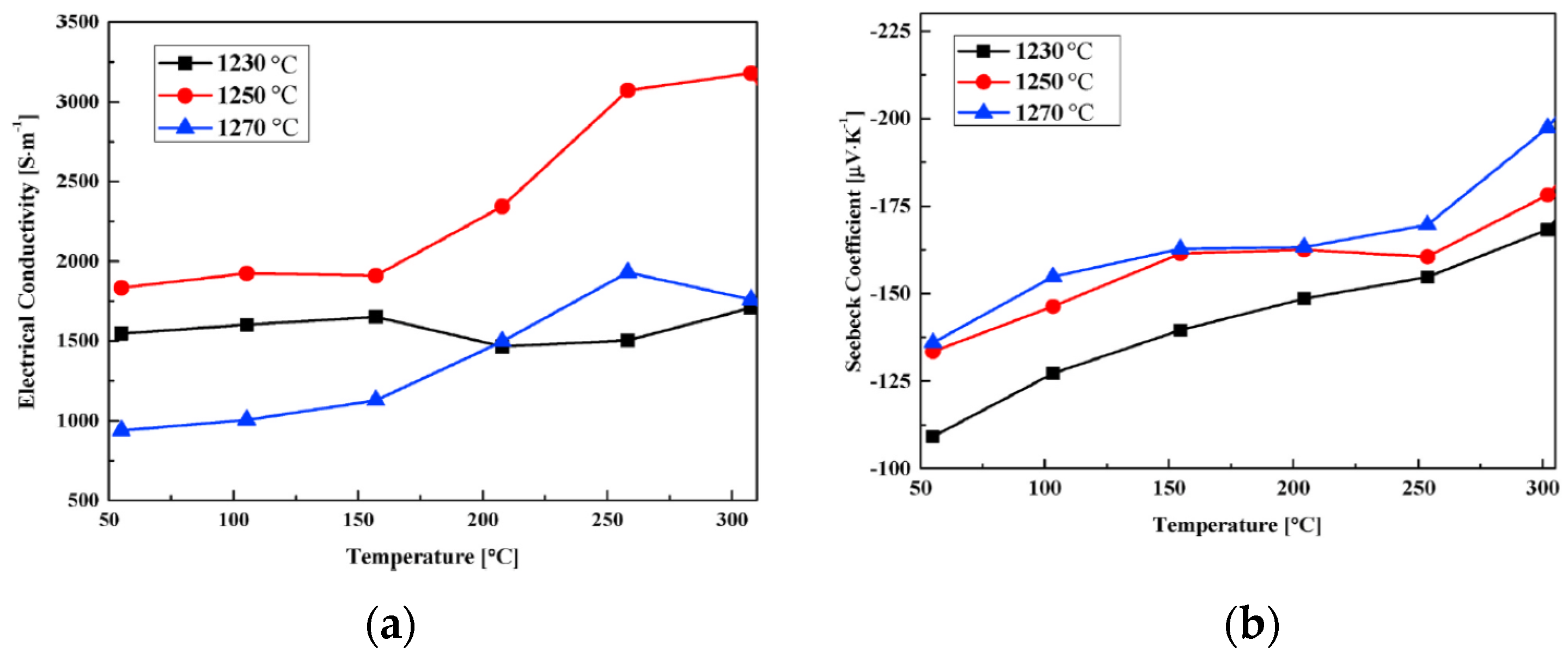
Figure 1. The electrical and thermoelectric properties of the Ni-doped ZnO made by thermal co-evaporation: (a) electrical conductivity, and (b) Seebeck coefficient. Reprinted with permission from [71], ©2020 Elsevier Ltd.
Coatings 11 00284 g001
Figure 2. Schematic showing integrated physical vapor deposition (PVD) processes: (a) magnetron plasma sputtering, and (b) plasma enhanced thermal evaporation. Reproduced from [72], ©2018, the authors.
Coatings 11 00284 g002
Figure 3. Scanning electron microscopic (SEM) images of the spray pyrolysis deposited (SPD) TiO2 coating containing nanofibers. Inset (a) shows the fiber size is around 30 nm. The substrate temperature was 350 °C. Reprinted with permission from [78], © 2015, Elsevier GmbH.
Coatings 11 00284 g003
Figure 4. (a) SEM image of nominal 25-μm TiO2 lines from liquid phase deposition, and (b) the corresponding EDX Ti X-ray map image confirming the selective deposition of TiO2 on the patterned surface. Reprinted with permission from [88], © 1999, American Chemical Society.
Coatings 11 00284 g004
Figure 5. SEM images of (a) the top view of the TiO2 nanotubes, (b) the surface morphology of the TiO2 nanotubes and Ag particles, (c) the top view of the CoO nanotubes, (d) the cross-section of the TiO2-CoO nanocables, and (e) the cross-section of the TiO2-CoO nanocables after sputtering Au coating and (f) the top view of the TiO2-CoO nanocables after sputtering Au coating. Reproduced with permission from [91], © 2010, Elsevier B.V.
Coatings 11 00284 g005
Figure 6. TEM images showing (a) TiO2 nanotubes, (b) the diffraction pattern of the TiO2 nanotubes, (c) TiO2-CoO nanocables, and (d) diffraction pattern of the TiO2-CoO nanocables. Reproduced with permission from [91], © 2010, Elsevier B.V.
Coatings 11 00284 g006
Figure 7. Procedures for nanocasting cobalt oxide and its electrical and thermal conductivities: (a) electrical conductivity, and (b) thermal conductivity. Reproduced with permission from [92], © 2019, Elsevier Inc.
Coatings 11 00284 g007
Figure 8. Computed Seebeck coefficients for (a) Mg3SiO, (b) Mg3GeO, (c) Ca3SiO, and (d) Ca3GeO assuming p-type (solid symbols) or n-type carriers (open symbols). Reproduced from [100], © 2019, the authors.
Coatings 11 00284 g008
Figure 9. Experimental measurements of (a) electrical resistivity, (b) Seebeck coefficient, and (c) thermal conductivity for orthorhombic Ca3SiO and Ca3GeO. Reproduced from [100], © 2019, the authors.
Coatings 11 00284 g009
Figure 10. (a) Resistivity of STO thin films deposited at 450, 650, and 750 °C as a function of temperature, and (b) ln(ρ) vs. 1/T of STO-450, STO-650, and STO-750 films, respectively. The dashed black line represents the linear fit. Reproduced with permission from [110], © 2020, Elsevier B.V.
Coatings 11 00284 g010
Table 1. Seebeck coefficients of liquid phase deposited thermoelectric nanocomposites.
TemperatureTiO2 (µV/K) CoOTiO2 + AgTiO2 + Ag + CoO
ΔVT@40 °C−220−93.33−393.33−300
ΔVT@45 °C−210−90−320−255
ΔVT@50 °C−172−68−296−208
ΔVT@55 °C−153.33−80−316.67−200
ΔVT@60 °C−125.71−71.43−274.29−162.86
ΔVT@70 °C−106.67−66.67−266.67−166.67
ΔVT@80 °C−98.18−60−245.45−129.09
ΔVT@90 °C−101.54−60−27.69−113.85
ΔVT@110 °C−78.82−56.47−207.06−108.24
ΔVT@130 °C−90.48−34.29−153.33−107.62
Reproduced with permission from [91], © 2010, Elsevier B.V.
Publisher’s Note: MDPI stays neutral with regard to jurisdictional claims in published maps and institutional affiliations.