1. Introduction
As technology advances, issues related to the wettability of solid surfaces by liquids become key to understanding phenomena occurring in real systems. Initially, they were used to describe the lubrication of solid surfaces moving relative to each other, and then to coat them with a chemically resistant layer—painting and coating. This second operation was carried out by depositing sprayed liquid drops on solid surfaces. Currently, the issue of wettability of solid surfaces is the most widely used when developing microfluidic systems and 3D printing methods.
The first physical model describing the state of equilibrium of a spherical droplet deposited on a flat substrate was formulated (in words) by Young [
1] in 1805. The derivation was supported by the analysis of geometrical relationships occurring in the considered case. However, obtained relation was presented [
2] in the form of a mathematical formula, called the Young’s equation, in 1911. Correlates stresses tangential to the wetted surface, acting on the line separating wetted and non-wetted areas, with the contact angle. It should be emphasized, however, that the forces and stresses perpendicular to the wetted surface are completely neglected in the derivation of this equation, although this contradicts the results of Laplace’s theoretical work [
3] (i.e., elevated pressure in the phase limited by the convex surface) and the force of liquid–solid adhesion acting on the entire wetted surface [
4].
In 1936, in the case of gas bubbles deposited on a solid substrate, it was found that the contact angle depends on their volume [
5]. As a result, the Young model was modified, introducing a term that takes into account the effect of stresses along the three-phase contact line. This line may shrink or stretch depending on the direction of this stress action described by its sign (positive or negative). Wenzel noticed that the energy of the liquid–solid substrate is proportional to its actual but not geometric surface area [
6]. In accordance with this conclusion, he introduced to the Young’s equation the roughness coefficient being the ratio of this real surface to the geometric one. He determined the roughness coefficient based on measurements of the contact angle for solid surfaces differing in texture and dimensions of unevenness. This model was extended by Cassie and Baxter [
7] in the case of porous substrates, on whose surfaces the deposited liquid enclosed gas in the pores. Another coefficient was introduced to the Young equation, which modified the value of the contact angle on a flat substrate to the contact angle that occurs at the inlet to the pores. Unfortunately, the paper does not show relationship between this angle and the contact angle of the entire droplet deposited on the porous substrate, only the equality of these angles was assumed.
For the case of a liquid drop surrounded by gas, but in a system not affected by external forces, the Laplace equation [
3] was solved at the end of the 19th century proving the spherical shape of such a droplet [
2]. However, it was not until several years later that it was established that the numerically selected parameter of the solution [
8] was the pressure difference between the droplet interior and surrounding gas [
9]. As a result, the Laplace–Young equation was formulated correlating this pressure difference with the curvature of the interface. The equation for determining the work of creating such a liquid drop with a specific radius in an isothermal system was derived from the analysis of the free energy of the liquid–gas system [
9].
Based on the equation describing the internal energy of the molecular multiphase system, Boruvka and Neuman derived an analogous relationship for the macroscopic system in which individual phases remain continuous [
10]. In the obtained equation, in addition to the main thermodynamic parameters, the internal energy of the system also depended on the interface energy, the length of three-phase contact lines, as well as on point energy sources. However, solving this relationship for a spherical drop deposited on the substrate and surrounded by gas was very difficult due to the need to maintain equal entropy in all phases. Moreover, the solution for the zero value of the exact differential of the internal energy of the system was identified with the minimum energy of the system, although this is only its necessary condition.
The application of the free energy of the system to describe the phenomenon [
11,
12] significantly facilitated the minimization of such a formulated model because for the isothermal system it was possible to neglect the entropy changes of its components i.e., phases. However, on the basis of classical thermodynamics, the obtained solution (for zero value of the exact differential of the free energy, i.e., necessary condition) could only concern the case of the thermodynamic equilibrium of the system [
13], preventing discussion of any other cases, and in particular determining the sufficient condition of occurrence of the minimum free energy of the system. This difficulty was eliminated by applying the principles of non-equilibrium thermodynamics [
14] for the system under consideration.
All of the thermodynamic models described [
10,
11,
12,
13,
14] provide the same solution, i.e., the Young’s equation modified by the term taking into account the force acting along the three-phase tension line. Only in last paper [
14] are the ranges of variability of physicochemical parameters for which the necessary and sufficient conditions for the minimum free energy of the system are met. It is worth noting here that in none of the thermodynamic models of the drop deposited on the substrate so far has been used, the generalized free energy equation [
15] was applied, even though some of the stresses in the liquid closely corresponds to those in elastic materials.
As early as the 1970s, it was proposed to analyze the wettability of solid surfaces by liquids based on molecular thermodynamics simulations [
16] using Lenard–Jones interactions [
17] inside each of the phases present in the system as well as on the interfaces. Despite a significant increase in the computational capabilities of computers, a significant limitation of these methods is the number of liquid molecules and solid substrate (currently at around 2 × 10
4) [
18,
19]. Such a number of water molecules correspond to the volume of a spherical drop 2.14 × 10
−9 μL, i.e., a droplet diameter 80 nm. In addition, simulations are conducted by treating such a small droplet as a two-dimensional object [
19] a priori assuming that the contact angle meets Young’s equation, i.e., it does not depend on its shape. Often, the simulation also ends when Rayleigh instabilities appear. All of these simplifications do not ensure that the drop of liquid has reached a state of equilibrium of forces.
It is noteworthy that the value of stress acting in the three-phase contact line determined experimentally for macroscopic droplets with a volume greater than 0.01 μL [
11,
12] is greater than this value determined on the basis of molecular interactions [
20] by 5–6 orders of magnitude. Therefore, if the value determined for molecular interactions is taken as the correct one, for macroscopic droplets deposited on the substrate the influence of stress of the three-phase contact line should be negligible. This in turn means that the effect of droplet volume on the contact angle is still unexplained.
In a number of systems, two contact angles are experimentally observed, at which the deposited drop remains motionless [
21,
22]. This means that for each of the angles (advancing and receding) the drop reaches a state of equilibrium of forces, however, the models formulated so far based on conventional thermodynamics do not indicate this opportunity. Only the model [
14] based on non-equilibrium thermodynamics allows such two solutions, one of which is stable and the other unstable. It should be emphasized, however, that such behavior is only possible within a very narrow range of variability of physicochemical parameters describing interfacial surfaces. This phenomenon is interpreted either by the molecular imperfection of the surface of the substrate [
20] or by the existence of conjoining / disjoining pressure in the liquid near the three-phase contact line [
21,
22]. This last explanation seems doubtful in view of the need to meet the Laplace condition [
3] in the entire volume of the liquid phase, i.e., a constant pressure value in it.
It is noteworthy that the absence of the adhesive force in the currently available physical models makes them practically useless for determining the adhesion, uniformity and durability of coatings applied on solid substrates. As a result, the need to meet the requirements of industrial applications forces researchers to perform a very large number of experiments. Moreover, the lack of theoretically justified equations does not give any chance to systematize or generalize the obtained experimental results. A clear example of such difficulties is the widely used physical vapor deposition (PVD) coatings [
23,
24]. In the case of microfluidic systems, in addition to the above-mentioned difficulties, the transfer of substances between successive droplets via the adhesive layer and the influence of the formed adhesive layer composed of biological substances or microorganisms on the contact angles of the immobilized drops is important [
25,
26,
27].
The aim of the work is to formulate a physical model of the liquid macroscopic droplet behavior deposited on an ideal isotropic substrate in the vicinity of the state of mechanical equilibrium of the system. All phases present in the system are treated as continuous and the system is not exposed to external force fields.
2. Theory
Before proceeding to formulating a physical model of the phenomenon, it is worth analyzing the way it is going during the experiment. After contact of the droplet with the substrate, the liquid begins to spontaneously spread over a solid surface. Movement of the liquid causes inertial forces that cause droplet shape oscillations, the higher the lower the viscosity of the liquid. As a result of viscosity, the oscillations disappear in time, and the droplet acquires its equilibrium shape. The phenomenon described in this way indicates that during the deposition of droplet, the mechanical energy (including surface energy) accumulated in it is converted into work, and then it is transformed into heat due to viscous interactions in the liquid.
2.1. Model Development
Assumptions made:
In the vicinity of the state of equilibrium of forces acting on the droplet, it takes the shape of a sphere segment, and the fluid velocity and its changes become so small that the inertial forces of the moving fluid and its impact on the surface between fluids due to the so-called dynamic pressure become negligible.
During droplet deposition on the substrate, the temperature of any of the system components does not change.
The liquid forming the droplet does not change its volume—the entire system under consideration is an isochoric system. As a result of the assumed isothermal nature of the system, it is possible to avoid the need to consider the issue of droplet evaporation [
14]. On the other hand, the assumption of complete insolubility of the components of both fluid phases allows to ignore the influence of the Marangoni effect.
Interactions on the spherical interface between fluid phases (the droplet and its surroundings, i.e., gas or liquid) are described by the Laplace–Young equation:
in which
means the pressure difference inside and around the droplet,
surface tension at the interface, and
the radius of the sphere segment (
Figure 1).
It is noteworthy that Equation (1) somehow converts stresses perpendicular to a curved surface into tangential stresses as well as implying a constant pressure value inside the spherical droplet. In addition, it indicates how this pressure will automatically change as the droplet spreads.
The pressure present in the liquid cannot be compensated on the surface of a flat substrate, and therefore the liquid will be repelled upwards (
Figure 1) trying to reproduce the fully spherical shape of the droplet. The expression describing this force is obtained by multiplying the Equation (1) by the area of the wetted surface:
where
is the radius of the wetted circular area.
At the same time, the liquid covering the wetted area will be attracted to the substrate by the force of adhesion described by the equation:
where
describes the adhesive force related to the unit of the wetted surface.
It is noteworthy that this force will be perpendicular to the wetted surface and directed downwards. A negative sign was introduced in the equation for formal reasons so that the unit force of adhesion was expressed by positive values. The magnitude of this force does not have to be equal to the multiple of the interaction forces between the individual molecules of the substrate and the liquid due to the fact that the distances between the molecules in the liquid and the solid can be different.
The liquid molecules on the three-phase contact line can interact differently with the molecules inside the liquid phase and with the adjacent phase molecules surrounding the droplet. As a result, a force tangential to the substrate may arise that stretch or shrink the wetted circumference. Similar to the Young’s equation, the direction of this force is parallel to the radius of the wetted area:
Parameter is the force which stretch (positive value) or shrank (negative value) the circumference of the wetted area expressed for its unit length.
Despite the low values [
20], but for formal reasons, we take into account the force acting along the boundary of the three phases, i.e., three phase tension line. This force acts perpendicular to the radius of the wetted area and only along the line of contact of the three phases. In line with the suggestions presented in the literature [
20], its value was assumed as constant:
It should be noted that the positive value of this force is responsible for increasing the length of the contact lines of the three phases, and its negative value for its contraction.
All the forces specified above are distributed on the surface (
,
) or on the wetted perimeter (
,
). So, finding their common point of application would be debatable. However, during the spreading of droplet on the surface, work is performed related to the movement of liquids along the respective coordinate axes, i.e., along the directions of acting forces. The differential work performed by the moving fluid can be written as the following sum:
where
is the length of the wetted perimeter.
Considering incompressibility of the liquid the expression for work formulated in this way can easily be associated with Pascal’s law. Constant liquid volume and the assumed shape of the spherical droplet allow linking together liquid displacements along both axes resulting in three equivalent equations:
where
,
and
are the net forces acting on the droplet along the
,
and
axes, respectively.
The equilibrium of forces acting on a droplet occurs when the net force on it is equal to zero.
According to the convention applied in thermodynamics, the change in the value of a state function is described as the difference in its value between the state after the transition and the state before the transition. If we apply this to isothermal and isochoric conditions (vide assumptions) then the differential change of free energy will be equal to the differential change of the mechanical energy of the system, and this will be equal to the differential work done in the system. This means that the system will achieve stable equilibrium when the following conditions are met:
If the relationship (10)–(12) is met, and the above relationships are not met, then the drop will be in a state of unstable equilibrium.
2.2. Model Solution
In the vicinity of the state of equilibrium of forces acting on the droplet, it assumes the shape of a sphere segment. Thus, known geometrical relationships can be used to determine its height:
the radius of the wetted area:
and length of the perimeter of wetted area:
where
is the radius of curvature of the spherical cap and
is the contact angle.
During deposition, the volume of the droplet does not change, so it can be expressed by the radius of the spherical droplet,
, it has just before contact with the substrate. In this way, the relationship between the radius of curvature of an already deposited droplet and the one still levitating above the substrate can be obtained:
After substituting Equations (2)–(4) to the relationships (10)–(12) and after applying Equations (16)–(19), we obtain expressions of forces acting on the droplet perpendicularly and tangentially to the wetted surface. Comparing them to zero sets the condition for the balance of these forces, i.e., the condition necessary for the minimum mechanical energy of the droplet.
It is noteworthy that after such transformations, the only independent variable in all equations is the contact angle,
. Additionally, in all equations the expressions standing in front of the curly brackets are always
different from zero. This in turn means that the condition of the balance of forces acting on a drop can be simplified to the following form:
Using the relations (13)–(15), Equations (16)–(22) and (23), it is possible to determine the relationships whose fulfillment is a sufficient condition for the minimum mechanical energy of a droplet deposited on the substrate:
where:
The parameters defined above should be treated as similarity numbers. The first one () is a measure of the ratio of the adhesive force acting on the interface between the droplet and the solid substrate to the surface tension force acting on the boundary of droplet and its fluid surroundings. The second () is a measure of the stretching (or shrinking) force of the wetted perimeter tangentially to the contact surface of the droplet with the solid substrate and parallel to the radius of the wetted area to the surface tension force acting on the interface between the droplet and the fluid environment. The third () is a measure of the ratio of the force acting along the three-phase contact line (tangent to the interfacial surface of the droplet and the solid substrate) to the force of the surface tension acting at the interface between the droplet and the fluid environment.
Due to the always positive value of the expressions standing in front of the brackets,
, relations (24–26) simplify into the following form:
3. Results and Discussion
The complexity of the derived equations does not make it possible to directly assess the properties of the solutions. For this reason, it is worth discussing a few simple systems and those described in the literature.
3.1. Young’s Solution
According to Young’s model, at the point of contact of the three phases, there is an equilibrium between the resultant of tangential stresses to the surface to be wetted and the projection (onto this surface) of the stress occurring at the interface between the fluids. These tangential stresses are caused by differences in the interaction of the droplet molecules and their surrounding molecules with the solid surface. The superposition of these tangential stresses fully corresponds to the tangential force to the surface (
) introduced during the derivation of this model. Therefore, if we assume that only this force acts in the analyzed system, the equation describing the necessary condition for the occurrence of the equilibrium of forces (23) will be simplified to the form:
The above result indicates that in the considered case, the real solutions of the model are possible for non-negative values of parameter limited by unity, . This in turn indicates that in the system under consideration there can only exist forces tangential to the surface to be wetted, stretching the perimeter of the wetted area.
After a simple transformation, we obtain an equation of the form closer to Young’s equation:
It follows from the above equation that its solution will be two contact angles symmetrically distant from the asymptote .
The Relation (30) describing the sufficient condition of minimum of mechanical energy of a droplet deposited on a solid surface will simplified to the form:
It is satisfied in the range of the variability of the contact angles . This means that in the case under consideration, the equilibrium of forces acting on the droplet will occur for two contact angles, but only within the given range, the achieved equilibrium of forces will be stable.
It is very important that both the Young’s model and the one formulated here confirmed the independence of the contact angle from the droplet volume. However, there are also significant differences between the two models, e.g., Young’s solution provides only one contact angle which increases as the tangential force to the surface decreases. In turn, in the formulated model, as the force tangent to the surface stretching the droplet increases, the smaller the angle increases and the larger one decreases, although the balance of forces is maintained for both. This is due to the fact that in the absence of a force stretching the drop over the surface, the balance of forces in the described system occurs only when the drop spreads over the surface to form a flat liquid layer () or when the drop retains its spherical shape (). However, only in the first case (for a smaller contact angle) will the equilibrium of forces be a stable equilibrium.
3.2. Improved Young’s Solution
In 1936, Vesselovsky and Pertzov [
5] proposed to introduce a term into Young’s equation that takes into account the effect of the stress force acting along a line occurring at the border of three phases. This slightly reduced the error of fitting the experimental data to the equation formulated in this way. In more recent works, such a modified equation is used as a boundary condition for solving the equation describing the deformation of the droplet shape caused by the force of gravity [
28,
29], i.e., by hydrostatic pressure, despite the fact that no external forces were taken into account during its derivation.
The presented model allows for the formulation an analogous relationship. It is enough in Equation (23) to equate the term describing the force of adhesion of the liquid to the surface of the substrate to zero, obtaining:
Unfortunately, the form of the obtained equation differs from that proposed in the literature.
In the considered case, Equation (34) describes the equilibrium state of forces acting on a droplet resting on a solid substrate. However, it is worth applying the Relation (30) to determine the range of variability of parameters
and
in order to determine the ranges of their variability in which this equilibrium is stable:
After a few transformations, we get:
Using the Equation (34), the above relation can also be presented for parameter
:
The dependence of the parameter
, determining the ratio of the force acting along the three-phase boundary line to the force acting on the interface between fluids, is shown in
Figure 2. The calculations made with the use of Equations (34) and (36) were used to create the graph.
As a result of the Relation (36), the diagram in
Figure 2 is divided into two parts, one of which concerns solutions of stable (permanent) equilibrium of forces acting on a drop, and the other (gray) solutions of unstable equilibrium. The first group of solutions is located under the line marked (
,
).
Contrary to the solution of Young’s problem presented above, given by Equations (31) or (32), the range of variability of the value of the coefficient seems unlimited. Only that for its value of all solutions obtained from the discussed model (regardless of the contact angle) are solutions of the unstable equilibrium, and for they correspond to a stable equilibrium of forces independently of contact angle values.
For a constant value of the parameter lying in the range and for the area of stable equilibrium of forces, the value of the parameter increases with the increase of the contact angle. This means that for a given system characterized by a constant value of unit stresses (used in the model), the contact angle will increase with the decrease of the radius, i.e., the droplet volume. Moreover, in this range of variability of parameter and a given value of parameter , the system will be characterized by only one stable solution, and apart from that, it will be able to have two more solutions for which the balance of forces will be unstable. Only for , there will be two contact angles corresponding to the balance of forces, the smaller the stable equilibrium, and the larger unstable equilibrium. On the other hand, for a constant value of parameter lying in the range , a stable balance of forces occurs in two areas; for small and large contact angles. In both of these areas, the value of the parameter increases with increasing contact angle. This means that in each of these areas, for a given system characterized by a constant value of unit stresses (used in the model), the contact angle will increase with the decrease of the radius, i.e., the droplet volume. Moreover, in this range of variability of parameter and a given value of parameter , the system will be characterized by two stable solutions; one for small contact angles and one for large contact angles, and besides it will be able to have one more solution (lying between the mentioned ones) for which the balance of forces will be unstable. It is worth noting that for the value of parameter solutions can be obtained only for negative values of parameter , which means that they will characterize a system in which the force acting along the three-phase contact line will shrink the wetted perimeter. The line delimits two cases where the force acting along the three-phase contact line changes its direction of action; for it stretches the wetted circuit, and for it contracts. This shows that for the variability range of parameter in the range , there is a discontinuity of solutions, consisting in the fact that decreasing the diameter (reducing the droplet volume) increases the parameter . However, exceeding the value of would result in a change in the direction of action force. However, for a given system, the values of physicochemical parameters cannot change, and even more so, the direction of the forces acting as a result of changing the direction of stresses cannot change. It should be remembered that in the derived model a spherical drop shape and a circular shape of the wetted area were assumed, hence this discontinuity of the solution may result in the need to change the shape of the deposited drop and the shape of the wetted area. However, this change can occur without the need to change the physicochemical parameters of the system components.
The relationship of the parameter
, defining the ratio of stress acting tangentially and in the direction of the
axis on the line delimiting the three phases to the stress acting on the interface between the liquid phases (the droplet and its surroundings), is shown in
Figure 3. Calculations made with the use of Equations (34) and (37) were used to create the graph.
As is the case in the previous figure, also in
Figure 3 there is a line determined on the basis of Equation (37) separating the graph into two parts; the part that concerns the stable equilibrium of forces acting on the droplet, and the part that shows the other solutions (gray). The line separating the two areas is denoted by (
).
The graph shown in
Figure 3 shows that for the parameter
exceeding the value of
, there are no solutions to Equation (34) determining a stable equilibrium of forces acting in the system under consideration and for
and a given (but any) value parameter
, there is only one solution that determines a stable balance of forces. Moreover, for the value of this parameter lower than
, all its solutions will represent a stable equilibrium of forces.
For the range of parameter values
and
, there can be only one solution determining the unstable equilibrium of forces. In the range of
and
, but for a given value of parameter
, apart from one stable solution, there may be at most two solutions determining the unstable equilibrium of forces. Similarly, in the range of
and
, for a given value of
, apart from one stable solution, there may be at most two unstable solutions. It is worth noting that in all these ranges of variability of parameter
, for its constant value, parameter
(corresponding to the solutions for a stable balance of forces) should increase with the increase of the contact angle. In the range of parameter variability
and
, the lines of solutions lying on the line
they intersect the line
. The reasons and consequences of such behavior of the system have already been described in the description of the diagram shown in
Figure 2.
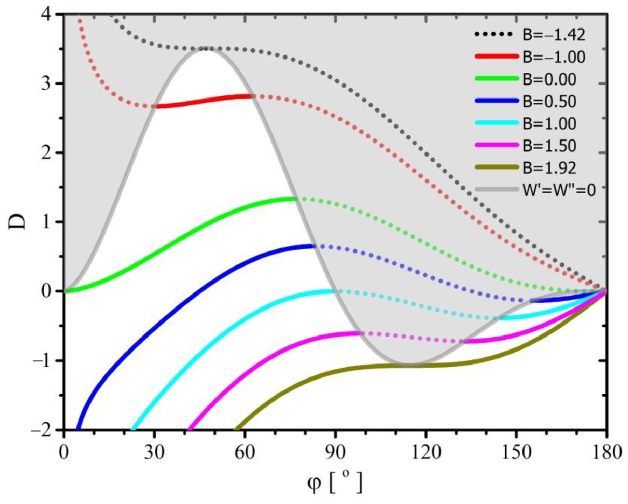
3.3. Influence of Adhesion Force on Droplet Deposition
So far, the literature has not analyzed theoretically the influence of the adhesive force on the behavior of the deposited droplet. Therefore, the discussion of this issue based on the solutions of the formulated model will be more precise.
Consider the case of a spherical droplet on which the force
is tangent to the surface of the substrate and parallel to the axis
and the adhesive force
acting on the droplet on entire wetted surface. For the sake of simplicity, we assume the absence of the
force acting along the line constituting the border of three phases. For such a system, Equation (23) determining the balance of forces is simplified to the form:
On the other hand, the condition for the existence of a stable balance of forces given by Relation (30) takes the form:
Due to the occurrence of asymptote (for
), the above inequality is met in two ranges:
Using Equation (39) one can determine the sufficient condition for the minimum mechanical energy of the droplet relative to parameter
:
The balance of forces acting on the droplet (39) can be achieved in a very wide range of variability of parameters
and
(
Figure 4 and
Figure 5). However, only in some of their variability ranges the system can achieve minimal mechanical energy (Equations (39) and Conditions (40)–(43), and this determines the existence of a stable equilibrium of forces. The gray area delimited by the lines marked
correspond to the unstable equilibrium of forces acting on the droplet.
Initially, let’s discuss only the area where the droplet achieves a stable equilibrium of forces. The graph in
Figure 4 shows that over the entire area for a constant value of parameter
, parameter
increases with increasing contact angle. Only that for
, the increase in the contact angle begins at a certain value lying on the border of the area of stable equilibrium of forces acting on the droplet and ends at
. However, for
, the contact angle may vary from zero to the value lying on the border with the area of stable equilibrium of forces. Only in the case of
, the contact angle may vary from
to
. It should be noted that the value of the
parameter is directly proportional to the radius
of the deposited spherical droplet. It follows that the contact angle of the deposited droplet should increase with its volume. It is also worth noting that for the value of the parameter
, the corresponding values of the parameter
should be negative, which would indicate the existence of adhesive forces pushing the drop off the substrate.
In areas where there is an unstable equilibrium of forces acting on the droplet, i.e., there is no minimum mechanical energy, for and , a decrease in the parameter is visible with an increase in the contact angle. It is easy to conclude that in the absence of stretching or shrinking forces acting on the droplet () the value of the contact angle occurs only when the adhesive force balances the pressure inside the droplet.
Figure 5 shows that in the area of a stable equilibrium of forces acting on the droplet, for a constant value of parameter
, the contact angle increases with the increase of parameter
. However, this increase is faster, the higher the value of parameter
. In the value range
, solutions satisfying the condition of a stable equilibrium of forces are limited, for small and large contact angles, by lines beyond which this condition is no longer fulfilled. However, for
, this restriction only applies to small contact angles. It is noteworthy that the lines were determined only for
, assuming the existence of only the attractive forces between the liquid molecules and the solid surface.
The graphs in
Figure 4 and
Figure 5 show that for non-zero values of parameter
, the droplet reaches a state of equilibrium of forces for two values of contact angles. At the same time only one of them corresponds to the minimum of its mechanical energy (stable equilibrium of forces), and the other is a state of unstable equilibrium. It is also noteworthy that with a constant value of the
parameter, but with an increase in the droplet volume, i.e., an increase in its
radius and a consequent increase in the
parameter, the contact angle increases, for which there is a stable balance of forces. On the other hand, the contact angle corresponding to the unstable balance of forces decreases. The results of experimental observations (carried out in the gravitational field) indicate the presence of two contact angles [
22]—advancing and receding. Thus, the formulated model indicates the mechanism of such a phenomenon, but without the need to introduce other, additional mechanisms. The more so as the results of the experiments do not determine the stability or instability of the force equilibrium in both of these cases, and the rheological properties of the liquid forming the droplets may significantly disturb the observation results, i.e., the rate of transformation of an “unstable” drop into a “stable” droplet.
One more aspect should be noted, resulting from the charts in
Figure 4 and
Figure 5. Looking at the definition of parameter
(27) and the graph in
Figure 4, one gets the impression that for the known value of parameter
and the ratio
, determined based on physico-chemical data, there is a limit on the volume of droplets characterized by the radius
. For
there should be the maximum, and for
the minimum droplet volume, for which solutions can be found in
Figure 4 and
Figure 5. However, this does not mean that droplets of different volumes will not wet the substrate, but that they will take a different shape from the sphere segment—vide assumption 1. However, for each of these shapes, in systems without external forces, the pressure in the entire volume of the liquid should be constant (the condition of keeping the curvature of the interface constant), otherwise the liquid will move—see the Navier–Stokes equation. This in turn will run counter to the mechanical equilibrium conditions of the system.
4. Remarks on the Model and its Experimental Verification
Although, according to Equations (27) and (29), the values of the parameters
and
depend on the droplet volume, their product has to be a constant value because it is expressed only by means of physicochemical parameters characterizing the system:
If we assume that the adhesion force acting on the droplet can only attract the liquid to the substrate, the sign of the above product is dependent on the direction of the force acting along the line separating the three phases. Thus, for a non-zero value of this product, there will be only two kinds of solutions. Only when the value of the product is equal to zero may there be three systems described in this paper.
The Laplace–Young Equation (1) requires that the sum of the principle curvatures of the liquid-surroundings interface should be constant and equal at every point of this surface. This means that at each point of this surface the pressure difference between the inside of the droplet and the surroundings has to be constant and the same at each point. Meeting this condition in a gravitational field is difficult due to the existence of hydrostatic pressure along the drop height axis when the substrate is perpendicular to the direction of the gravity force. The more so because the shape of the drop will differ from the spherical [
28,
29]. Nevertheless, it may be tempting to establish a condition for which the influence of hydrostatic pressure will be small compared to the internal pressure in the spherical droplet. The ratio of both of these pressures can be written as:
where
is the difference in density between the droplet and its surroundings,
is the acceleration of gravity, and
the height of the drop (at its apex). The other values are already described in the paper.
In order to determine the height of a droplet at its apex, it is necessary to solve the equation defining its shape in the gravitational field [
28,
29]. It is a fairly simple numerical problem. However, the real problem is to determine the boundary condition based on the balance of forces acting on the droplet on the contact surface of the drop with the substrate. There is no such solution yet, although it is possible to obtain it using the methodology described in this paper. However, taking into account the fact that the hydrostatic pressure is to be relatively small compared to the pressure inside the droplet, its shape will also slightly differ from spherical. Thus, the given Equation (16) can be applied, and after substituting the remaining geometric dependencies, Expression (45) will obtain the form:
Taking into account the experimental results given in paper [
29], for which the parameters had the following values:
[kg/m
3],
[m],
[N/m], the value
was calculated. However, since even in the case of such small droplets their shape slightly differed from the spherical one, the value of
should be lower.
It is noteworthy that the influence of gravity can be reduced by depositing liquid droplets on the substrate in the surroundings of another liquid with a density as closely as possible to that of which the droplets are formed. Of course, both liquids should mix very poorly with each other. However, the largest range of droplet volume variability applied in the measurements could be achieved by reducing the acceleration of gravity, e.g., in the conditions of the ISS space station, where the acceleration is only .
It is noteworthy that the results of experiments conducted during parabolic flights may be flawed by a significant error. The duration of the weightless condition during such a flight may be too short for the liquid droplets deposited on the solid substrate to reach a state of equilibrium of forces.


