Article

Self-Healing Properties of Cerium-Modified Molybdate Conversion Coating on Steel

by
Aliona Kirdeikiene
,
Olga Girčiene
,
Laima Gudavičiūte
,
Vitalija Jasulaitiene
,
Algirdas Selskis
,
Skirmante Tutliene
,
Monika Skruodiene
,
Jurgis Pilipavičius
,
Jurga Juodkazyte
and
Rimantas Ramanauskas
*
Center for Physical Sciences and Technology, Sauletekio 3, LT-10257 Vilnius, Lithuania
*
Author to whom correspondence should be addressed.
Coatings 2021, 11(2), 194; https://doi.org/10.3390/coatings11020194
Submission received: 11 January 2021 / Revised: 28 January 2021 / Accepted: 3 February 2021 / Published: 8 February 2021
(This article belongs to the Special Issue Thin Films and Coatings for Active Corrosion Protection of Metals)

Abstract

:
Environmentally friendly alternatives to chromium—phosphate/molybdate and cerium-modified phosphate/molybdate conversion coatings—were deposited on a carbon steel surface. Different surface analytic techniques were applied to obtain complementary information on the composition, element distribution morphology and inner structure of the coatings in order to establish the relationship between coating properties and corrosion performance. The higher protective and stronger self-healing abilities were found for phosphate/molybdate/cerium conversion coating deposited in a sulphate-containing solution. The protective barrier strength was found to be related with certain aspects of the coating morphology such like homogeneous distribution of fine crystallites and, hence, lower number of structural defects. The self-healing ability depended on both, the composition (higher amount of Ce(IV)) and micro-structural characteristics, such as defectiveness, of the conversion layer.

1. Introduction

Steel is the most frequently used metal in various industries; however, its susceptibility to corrosion in many environments limits its application. Therefore, a wide variety of coating processes have been developed to achieve coatings with desirable properties to meet certain surface protection requirements. Chromate conversion coatings have been widely applied for corrosion protection of metals, as providing both, barrier and self-healing effects. However, legislative pressure regarding prohibition of Cr(VI) compounds pushed scientists to look for suitable alternatives. Significant efforts have been invested to develop environmentally friendly technologies, including the ones based on phosphates [1,2,3,4], molybdates [5,6,7,8,9] and rare earth (cerium) based chemistries [10,11,12,13,14]. However, only few of them have been able to come close or meet the corrosion protection requirements.
Phosphating is one of the most widely used passivation treatments for steel. Formation of this conversion coating occurs via the growth and coalescence of phosphate crystals, what inevitably leaves pores, which are detrimental for the metal corrosion resistance. The protective ability of phosphate coatings on steel could be improved by the passive layer modification with Mo compounds [6,15]. Molybdates are considered to promote the passive state on the surface of steel, which reduces the passivation current through formation of a stable film and extends the anodic passivation range [8].
Moreover, an active self-healing of defects is required for the total or partial repair of coated areas damaged by ageing or unexpected aggressive events. However, due to the fact that molybdates are weaker oxidizing agents than chromates the resulting coating does not demonstrate a sufficient capacity of self-repair. This ability can be achieved or increased by introduction of specific corrosion inhibitors into the coating system. Rare earth metal ions, especially cerium salts, are known to inhibit the corrosion processes on several substrates such as galvanized steel [10,12,13], steel [14,16], aluminum and its alloys [17,18]. Ce conversion coatings form physical barrier between the substrate and environment, and, more importantly, exhibit self-healing ability due to Ce(III)/Ce(IV) redox reactions. However, these coatings on steel surface did not ensure high corrosion resistance mainly due to the cracks and pores present in their structure [19].
Cerium and molybdate compounds as separate are widely known for their inhibiting action in corrosion processes of metals. There is a number of reports suggesting that a combination of different inhibiting species such as rare earth elements with inorganic anions can provide a synergistic inhibition effect, rendering a superior corrosion protection for alloys and metals [20,21,22,23,24]. However, the formation of resistant and self-healing coating on steel is still a challenge. In spite of the increasing number of papers in recent years, little attention has been paid to the correlation between corrosion performance and coating parameters, such as structure, morphology and composition. The aim of the present study was to deposit cerium-modified molybdate conversion coatings on a carbon steel and to analyze the possible synergistic action of Ce and Mo on the protective and self-healing properties of these coatings.

2. Materials and Methods

2.1. Sample Preparation

Carbon steel specimens (10 mm × 20 mm × 1 mm) previously polished with emery paper up to grade 400 with polishing equipment Tegramin-25 (Struers, Ballerup, Denmark), degreased with ethanol and rinsed with distilled water, were used as the base metal electrodes. Phosphate-molybdate (Fe/P-Mo) and phosphate-molybdate-cerium (Fe/P-Mo-Ce) coatings were deposited on steel surface. The solution used for the Fe/P-Mo chemical conversion treatment contained: 0.15 M H3PO4, 0.003 M H2C2O4, 0.1 M Na2MoO4 and 0.02 M NaNO3, pH ~ 4.5, 50 °C. Ce-modified conversion coatings were deposited by simple immersion of Fe/P-Mo samples into one of two solutions (pH ~ 5, 25 °C) containing 0.05 M Ce(NO3)3 (Fe/P-Mo-Ce1) or 0.05 M Ce(NO3)3 + 0.025 M Na2SO4 (Fe/P-Mo-Ce2). All electrolytes were prepared from analytical grade chemicals and deionized water. In order to create an artificial defect and to evaluate the self-healing ability of the investigated conversion coatings the deposited samples were manually scratched with metallic needle (the width of scratch ~ 30 µm) to expose a steel surface.

2.2. Electrochemical Measurements

The corrosion behaviour of deposited coatings was investigated in an aerated stagnant 0.5 M NaCl solution. All electrochemical measurements were performed at ambient temperature with an Autolab PGSTAT302 potentiostat (Metrohm AG, Herisau, Switzerland) using a standard three-electrode system with a Pt counter electrode and a saturated Ag/AgCl reference electrode. All potential values are reported versus this electrode. The corrosion current densities (icorr) were determined from voltammetric measurements performed with the potential scan rate of 0.5 mV·s−1 from cathodic to anodic region.
The measurements of electrochemical impedance spectra (EIS) were performed at the open circuit potential with the FRA2 module applying a signal of 10 mV amplitude in the frequency range from 20 kHz to 0.001 Hz.

2.3. Morphology and Composition

A focused ion beam scanning electron microscope (FIB-SEM) system Helios Nanolab 650 (ThermoFisher Scientific, Hillsboro, OR, USA) with an energy dispersive X-ray (EDX) spectrometer INCA Energy 350 (Oxford Instruments, Abingdon, UK) and X-Max 20 (Oxford Instruments, Abingdon, UK) silicon drift detector was employed for imaging of the surface morphology, for cross-section preparation and imaging, as well as for investigations of chemical composition. The morphology of samples was examined using 2–3 keV energy secondary electrons, EDX spectra were obtained at 1.6 nA probe current and 20 kV high tension.
The same equipment was also used for the preparation of thin film samples for further examination in transmission electron microscope (TEM). TEM Tecnai G2 F20 X-TWIN (ThermoFisher Scientific, Hillsboro, OR, USA) with energy-dispersive X-ray spectrometer (EDX) with r-TEM detector was used for measurements of Ce, Mo, P, O and Fe concentration depth profiles in deposited coatings at 200 kV. A protective Pt layer of 1 μm thickness was deposited on a sample selected area of 20 μm × 3 μm before a cross-sectioning or sample preparation for TEM. A focussed Ga+ ions beam was used in the sample cutting at 30 kV. Omniprobe Model 100.7 nanomanipulator (Oxford Instruments, Abingdon, UK) was applied for TEM lamella lift-off. Final thinning was performed on the attached to TEM grid lamella.
The X-ray photoelectron spectroscopy (XPS) studies were performed by a spectrometer ESCALAB (VG Scientific, East Grinstead, UK) using X-radiation of MgKα (1253.6 eV, pass energy of 20 eV). To obtain depth profiles, the samples were etched in the preparation chamber by ionized Ar at a vacuum of 5 × 10⁻⁴ Pa. An accelerating voltage of ca. 1.0 kV and a beam current of 20 µA·cm−2 were used.

3. Results and Discussion

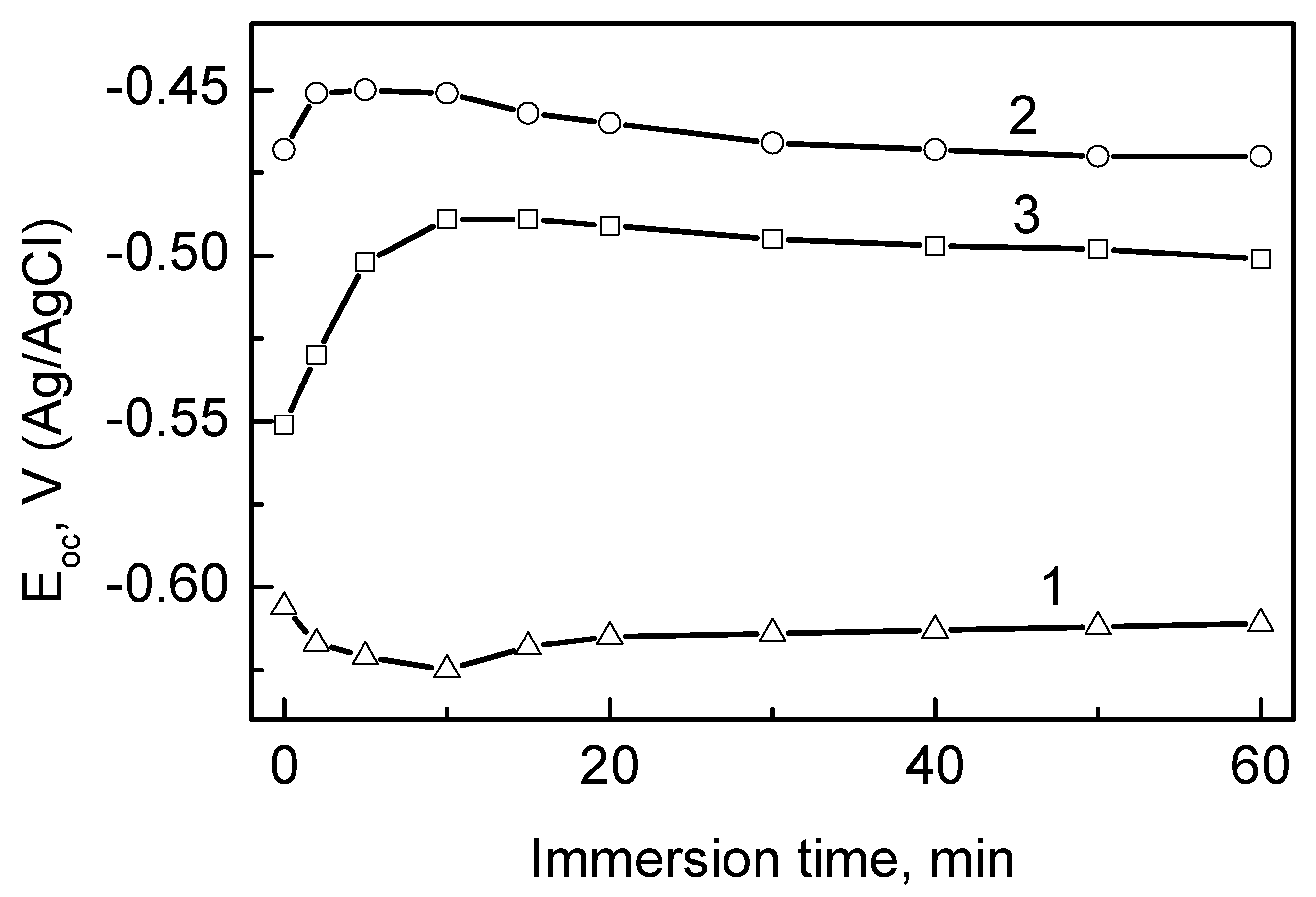
3.1. Formation of Conversion Coatings

In phosphating process, the surface of a carbon steel in contact with an acidic phosphate solution covers with a conversion layer, which contains a mixture of iron phosphate and oxide. According to potential-pH diagram of Fe in molybdate-containing solution, insoluble FeMoO4 is formed at slightly acidic pH and the process takes place at the potentials, where active dissolution of Fe occurs [5]. The curve 1 in Figure 1 represents the evolution of the open-circuit potential (OCP) of steel electrode immersed in the phosphate solution containing Mo ions. The dissolution process of substrate is accompanied by a slight decrease in the potential values at the initial stage of the conversion coating formation, with the following stabilization at approximately −0.620 V (Ag/AgCl). This observation implies that ca. 20–30 min was enough to form phosphate/molybdate layer (Fe/P-Mo) on the steel surface.
As the protective and structural properties of Ce conversion coatings depend on the anionic composition of the deposition solution [12] two Ce(NO3)3 electrolytes, with and without sulphate ions, were applied. The potential evolution for Fe/Mo-P samples immersed in the 0.05 M Ce(NO3)3 and the 0.05 M Ce(NO3)3 + 0.025 M Na2SO4 solutions are presented in Figure 1 (curves 2 and 3). In both solutions the formation of the conversion film led to an important ennoblement of the OCP values and after 20–30 min the potential plateaus around~ −0.500 to −0.470 V (Ag/AgCl). This plateau suggests that the reaction occurring at the interface reached the steady state and that conversion process had been completed.

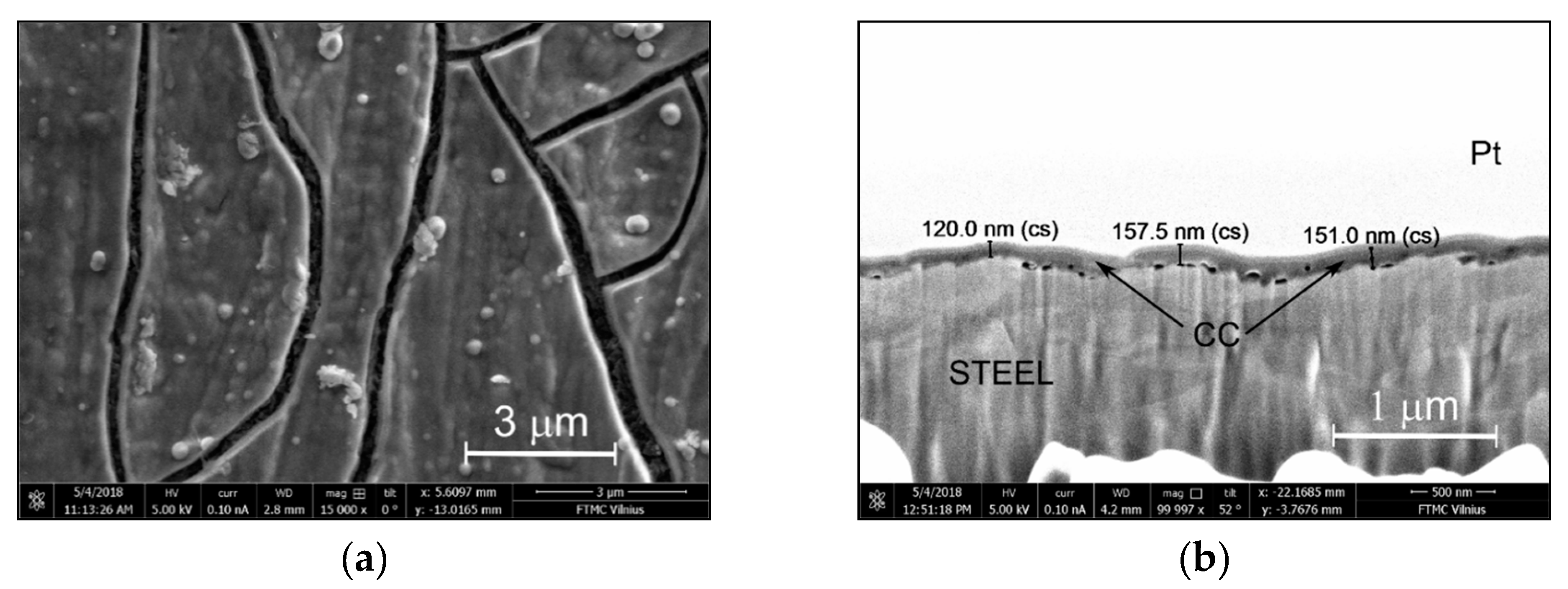
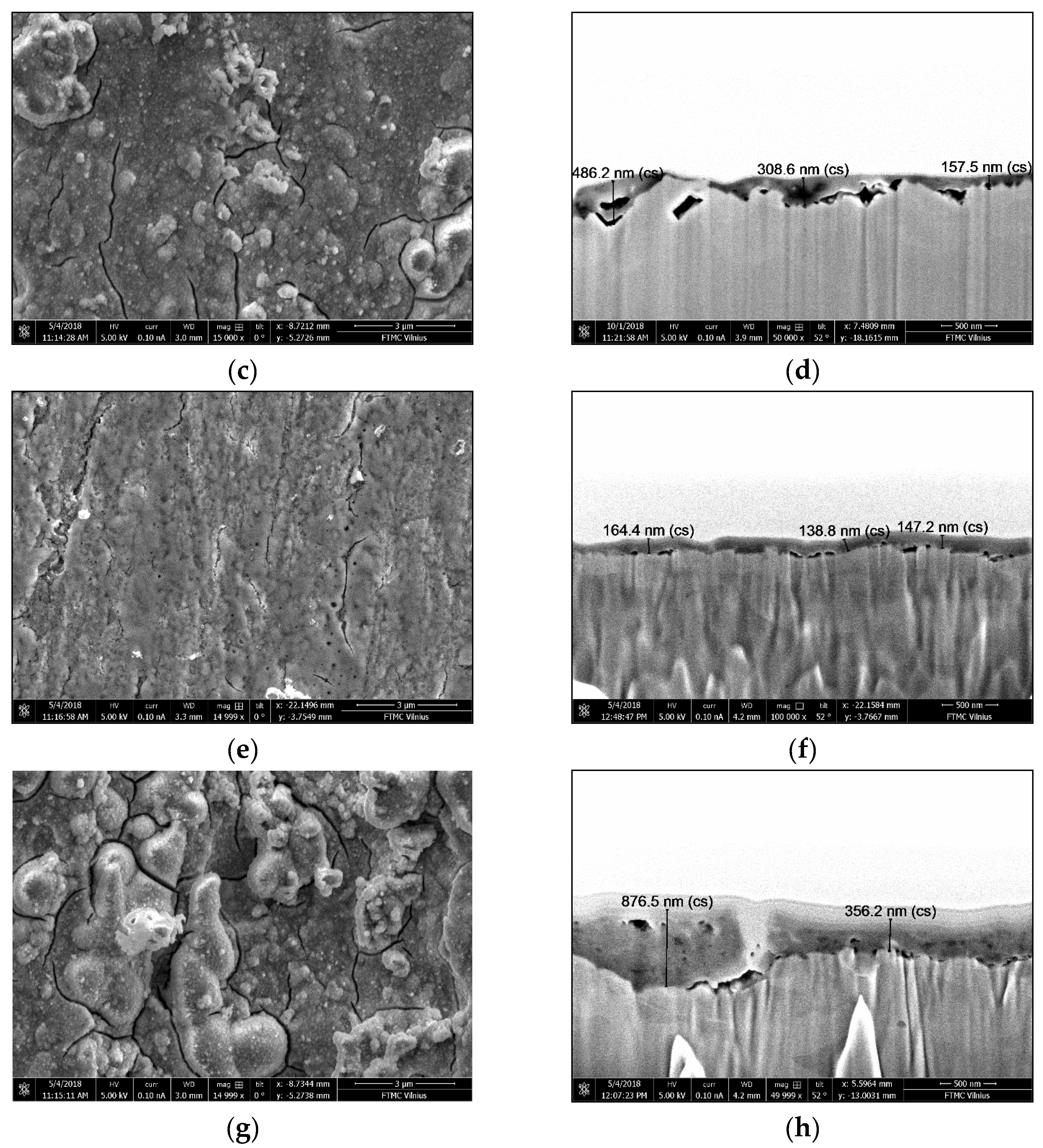
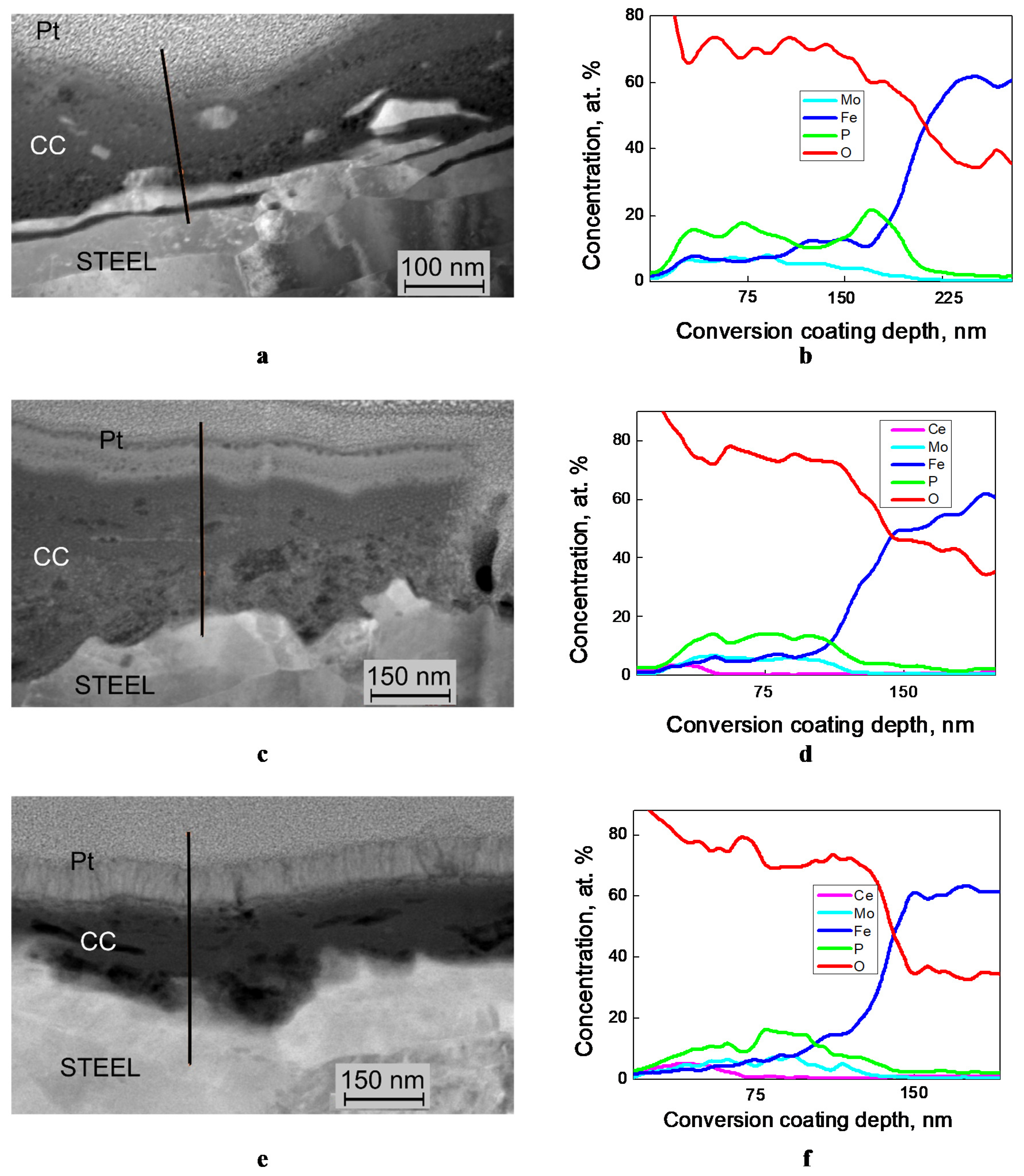
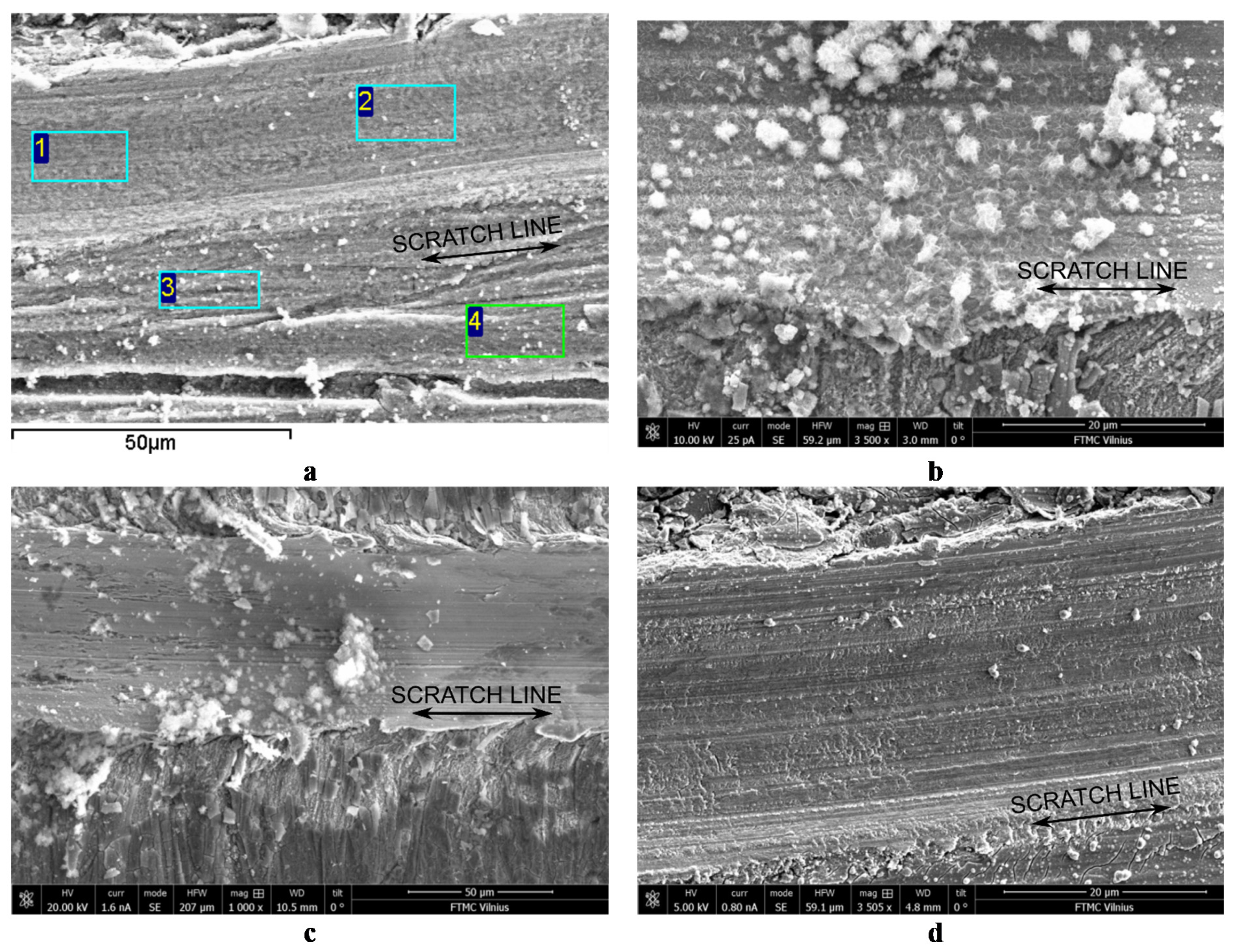
3.2. Surface Morphology and Inner Structure

A cracked “dried riverbed” morphology is typical for the molybdate-containing conversion coatings, what has been reported by a number of authors [8,22,25] and such morphology is observed in the case of the deposited Fe/P-Mo coatings as well. SEM image of the sample is presented in Figure 2a. The presence of surface cracks in μm range or larger could be related to the increase of stress induced by the film thickness. Alternatively, the cracks could form during the drying procedure performed at the end of the conversion process. The quality of deposited Fe/P-Mo coating appeared to be significantly influenced by the process duration. The increase in the conversion time up to 0.5 h led to the increase in the density of cracks in the film, therefore the process duration was limited to 20 min. According to the SEM image of the cross-section (Figure 2b), the Fe/P-Mo layer continuously covers steel surface, while its thickness varies in the range from 120 to 170 nm, with the average thickness value of ca. 150 nm. Meanwhile, the average thickness of a pure phosphate coating on steel surface, deposited in the same solution, was detected to be higher (200 nm) compared to Fe/P-Mo sample [26]. In addition, Mo-containing samples exhibited some cracks at the interface between conversion film and substrate (Figure 2b).
As sulphates in Ce(NO3)3 solution act as grain refiners and growth inhibitors of the Ce-containing conversion layer [12], the latter conditions are expected to affect the surface morphology and inner structure of the Ce-modified Fe/P-Mo coating. SEM images of these coatings are presented in Figure 2c–f. Indeed, a non-uniform thickness of the conversion layer, which varied between 160 and 490 nm and the presence of randomly located additional crystalline aggregates, with dimensions between 0.5 and 2.5 µm, on the surface of it, were typical characteristics of the Fe/P-Mo-Ce1 coating, the top layer of which was deposited in a pure Ce(NO3)3 solution (Figure 2c,d). Meanwhile, the presence of the sulphate ions in the Ce solution, reduced the number of structural defects such like cracks, as well as the thickness of the Ce-containing conversion layer (Figure 2e,f), which varied between 130 and 200 nm. Thus, it is obvious, that the presence of sulphates increases homogeneity and quality of Ce-modified conversion layer. Similarly to Fe/P-Mo coating formation, the longer time of the sample treatment in Ce(NO3)3 solutions led to the appearance of a significant number of structural defects (Figure 2g,h).

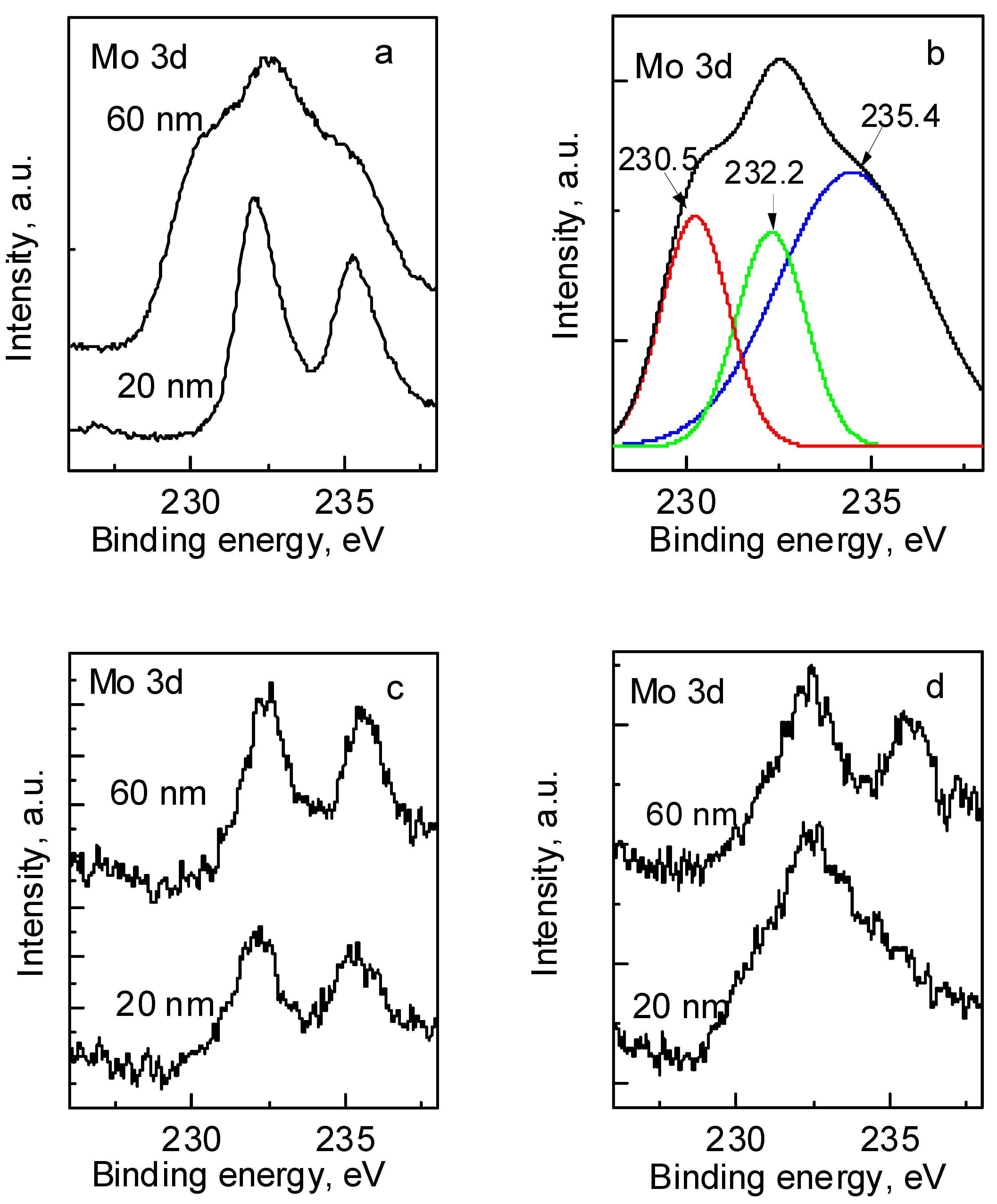
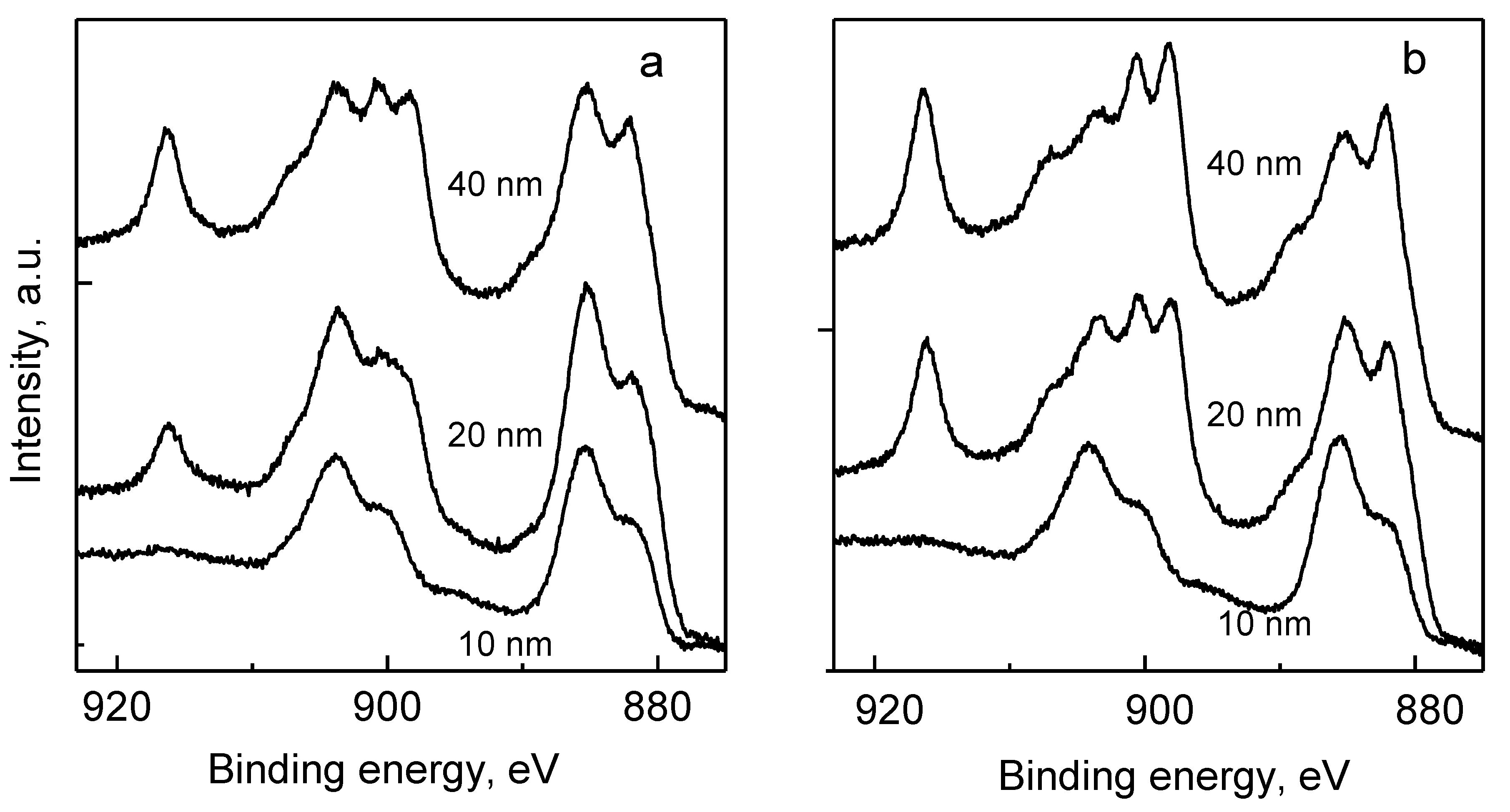
3.3. Chemical Composition

The chemical composition of the investigated conversion coatings was analysed applying EDX and XPS techniques. Due to the moderate thickness of the conversion layer the EDX results obtained for the samples prepared for SEM analysis yielded reliable information only on the average concentrations of Mo, Ce, P, O and Fe in the deposited coatings (Table 1). While the amounts of P and Mo in all the investigated samples were very close and varied in the range between 1.2 at.% and 1.8 at.%, the concentration of Ce in the conversion layer was higher for coating deposited in sulphate-containing solution (2.28 at.%) compared to sample deposited in bare nitrate one (1.75 at.%).
More precise information on the composition and, especially, on the distribution of the elements in the conversion layer can be obtained from EDX measurements of FIB-prepared thin film. TEM images of the cross-sections of investigated coatings with analyzed regions indicated and the element distribution profiles are presented in Figure 3a–f. The thickness of the conversion coatings due to both, initial steel surface morphology and peculiarities of the conversion process varies from place to place Figure 3a,c,d. However, it can be observed that Fe/P-Mo-Ce2 coatings deposited in sulphate-containing Ce solution were more compact with less number of the structural defects. (Figure 3e).
EDX analysis revealed that up to the depth of 120–150 nm of investigated conversion coatings the concentrations of Fe and Mo were very close and varied between 4 at.% and 7 at.%, while the amount of P varied in the range between 10 at.% and 18 at.% and was slightly higher for the Fe/P-Mo sample. The amount of Ce was detected to be higher in the sample deposited in the sulphate-containing solution as the maximal value reached up to 5 at.%, while for the sample deposited in bare Ce(NO3)3 solution this value was close to 3 at.%. Besides, Ce in Fe/P-Mo-Ce coatings was located in the outer part of the conversion layer and was detected up to the depth of 50 and 70 nm in Fe/P-Mo-Ce1 and Fe/P-Mo-Ce2, respectively (Figure 3e,f).
The chemical state of the elements in the conversion coatings was characterized by XPS measurements. Taking into consideration the elements, which may be responsible for the self-healing capability of the conversion films, the oxidation states of Mo and Ce were analyzed. The high-resolution Mo 3d spectra of Fe/P-Mo and Fe/P-Mo-Ce samples were recorded after different times of the surface sputtering with Ar ions and are shown in Figure 4 for the depths of 20 and 60 nm. Even distribution of Mo in the Fe/P-Mo coating was observed up to the depth of 90 nm and concentration of this element was close to 11 at.%. As shown in Figure 4b, the Mo 3d spectrum can be deconvoluted into three peaks. The peaks at 232.2 and 235.4 eV originate from the Mo6+ state in trioxide MoO3, whereas the peaks at 230.46 and 233.63 eV correspond to the Mo4+ state in dioxide MoO2 [22,25,27,28]. The molar ratio of Mo(VI) and Mo(IV) compounds was determined to be 3:2.
Meanwhile, the outer layers of Ce-modified Fe/P-Mo-Ce1 and Fe/P-Mo-Ce2 coatings contained significantly lower amounts of Mo, the concentration of which varied from 2 to 4 at.%. The molar ratio of Mo(VI) and Mo(IV) compounds determined similarly as for Fe/P-Mo sample, in the case of Fe/P-Mo-Ce one was ~4:1 and was close to that stated by the authors of [22]. The latter results imply that during modification of Fe/P-Mo coating with Ce ions, the total amount of Mo in the outer layer of the coating decreases, while the fraction Mo(VI) increases.
The XPS spectra for the Ce 3d region recorded at the different depths of Fe/P-Mo-Ce1 and Fe/P-Mo-Ce2 coatings are presented in Figure 5. The amount of Ce up to the depth of 40 nm varied between 7 at.%–10 at.% and 8 at.%–13 at.% for Fe/P-Mo-Ce1 and Fe/P-Mo-Ce2 coatings, respectively. In the Ce 3d spectra, three different regions can be identified. The first one in the binding energy range from 880 to 890 eV corresponds to Ce 3d5/2, the second one at the binding energies from 890 to 910 eV includes the zone where the Ce 3d3/2 and Ce 3d5/2 spectra overlap, and the third one is due to the emergence of the satellite peak associated with Ce 3d3/2 at a binding energy value close to 917.0 eV [10,11,12]. This peak is of a crucial importance for determination of the oxidation state of cerium because its presence is only associated with Ce (IV). The percentage of Ce(IV) was calculated according to the equation [29]:
Ce4+% = µ%/14 × 100
where µ is the percentage of the satellite peak area at 916.7 eV with respect to the total Ce 3d peak area.
It should be noted that there might be some errors in the data regarding determined Ce(III)/Ce(IV) ratio, due to the possibility of the reduction of Ce(IV) to Ce(III) during Ar sputtering. However, it is obvious, that up to the depth of 40 nm, sample Fe/P-Mo-Ce2 exhibited ~20% ± 5% higher percentage of Ce(IV) with respect to the total Ce quantity compared to sample Fe/P-Mo-Ce1.
Cerium conversion coatings can thus be described as a mixture of Ce(III) and Ce(IV) compounds, while the presence of SO42− ions in the Ce deposition solution leads to higher amount of Ce compounds in the coating as well as higher percentage of Ce in the higher oxidation state. XPS data indicated as well, that the addition of SO42− to the conversion solution leads to an incorporation of up to 1 at.% of S into the coating.

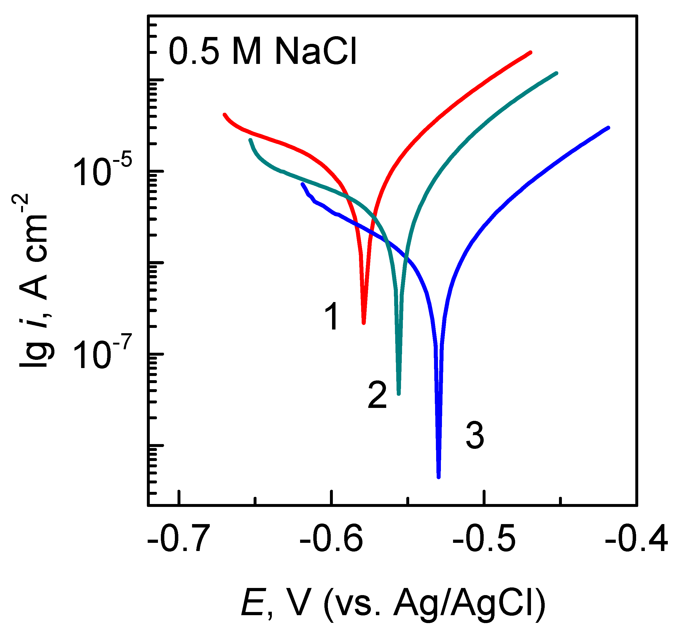
3.4. Protective Ability

The protective ability of investigated conversion coatings was evaluated on the basis of voltammetric measurements, which were carried out in 0.5 M NaCl solution. The polarization curves of the investigated samples are shown in Figure 6, while the values of the corrosion current (icorr) densities, determined from Tafel line extrapolation and other electrochemical parameters are listed in Table 2. Fe/P-Mo-Ce2 samples exhibited the lowest values of icorr among all the investigated coatings (~2.7 × 10⁻⁷ A·cm−2), whereas corrosion current densities of Fe/P-Mo and Fe/P-Mo-Ce1 samples were close enough and were higher by an order of magnitude (~2 × 10⁻⁶ A·cm−2). The protective efficiency of the coatings, P%, was calculated according to the equation [11,12]:
P%= (iocorricorr)/iocorr × 100
where iocorr and icorr denote the corrosion current density of the bare steel and that of the electrode with the conversion coating, respectively. The calculated value of P% increased from 59% for Fe/P-Mo sample up to 95% for Fe/P-Mo-Ce2. It is obvious that Ce conversion coating deposited in a sulphate-containing media exhibited the highest protective ability among the coatings investigated. The comparable protective abilities of Fe/P-Mo and Fe/P-Mo-Ce1 and similarity of the composition between Fe/P-Mo-Ce1 and Fe/P-Mo-Ce2 coatings, implies that higher protective ability of the conversion layer is related probably with the structural parameters rather than with the composition of the coating. The latter observation can be corroborated by the results of our previous studies, where similar higher values of icorr (1.6–1.7 × 10⁻⁶ A·cm−2) were determined for Ce layers deposited directly on a bare or phosphated steel surface [26]. In addition, the latter samples possessed similar structural defects like Fe/P-Mo and Fe/P-Mo-Ce1 coating. It seems that fine crystals of Fe/P-Mo-Ce2 conversion film facilitate the coverage of the coating, what yields homogeneous distribution of the conversion layer on steel surface resulting in a lower number of structural defects, what, in turn, improves the corrosion resistance of the conversion coating. As the average thickness of Fe/P-Mo-Ce2 was the lowest among the conversion coatings investigated, it can be assumed that coating thickness is not always a reliable indicator of corrosion resistance, because the thickest Fe/P-Mo-Ce1 did not perform well in corrosion tests.

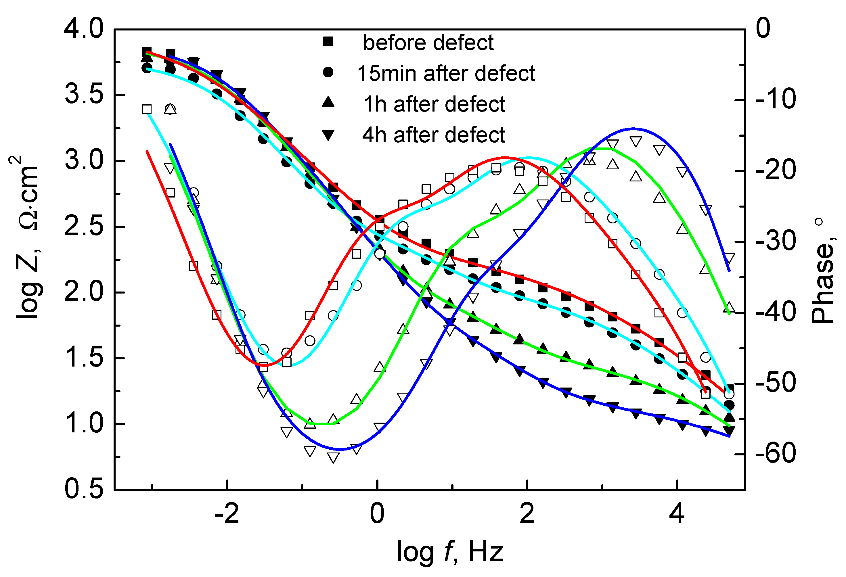
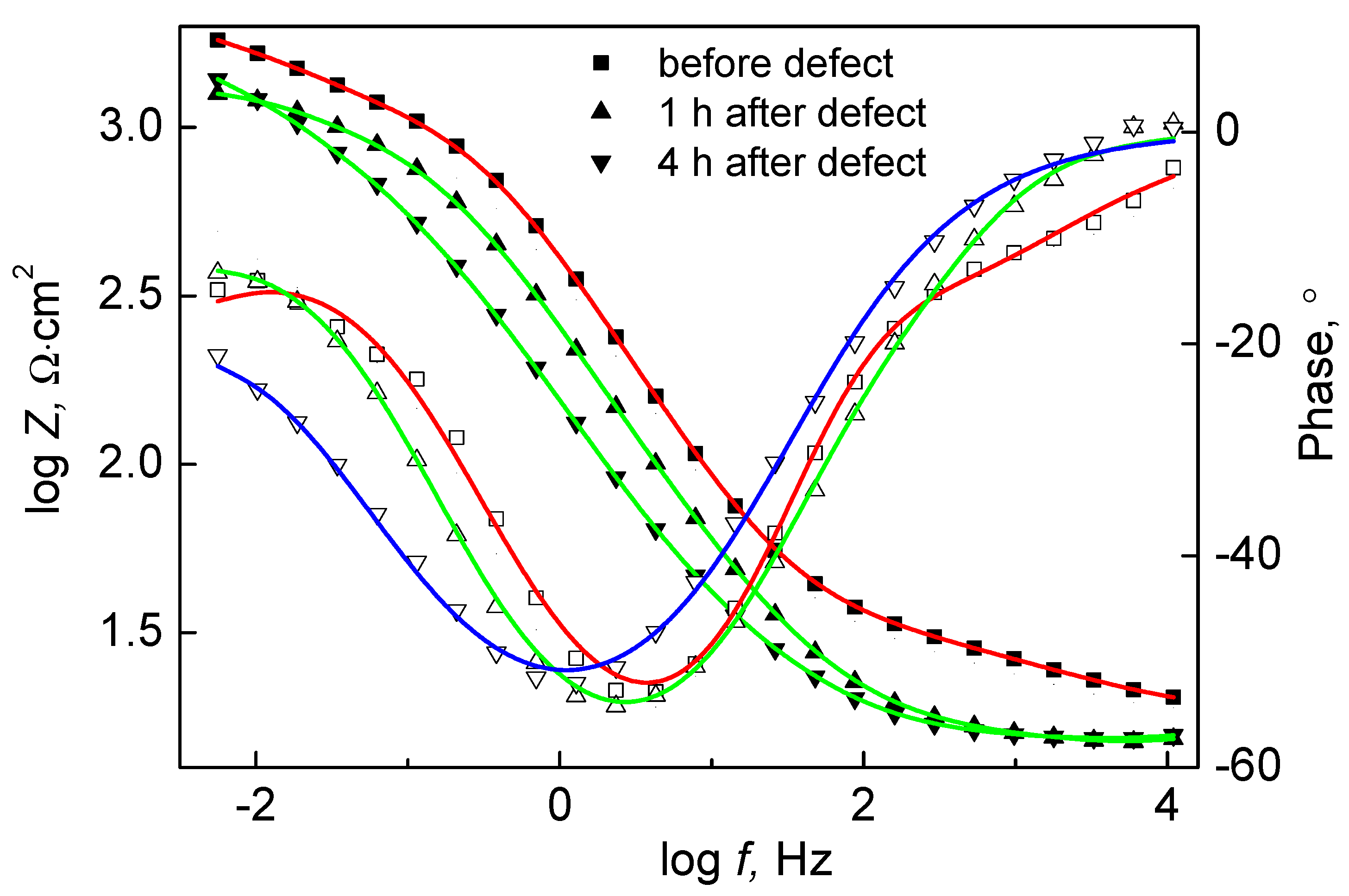
3.5. Self-Healing Ability

In order to assess the self-healing ability of investigated conversion coatings, a set of studies were carried out on samples with partially removed conversion layer, what was done by mechanical scratching with a sharp metallic needle. The average chemical composition of the areas in the fresh scratches (areas 1 and 2 in Figure 7a) was determined by EDX measurements and it was found to be close to the steel composition, while the results obtained in the analysed areas 3 and 4 (Figure 7a) were close to those, presented in Table 1. These samples were immersed into aerated 0.5 M NaCl solution for up to 4 h and SEM analysis of the surface morphology was carried out afterwards. The obvious differences in the sample corrosion behaviour were observed. Even after one hour of exposure Fe/P-Mo coating exhibited the abundant presence of steel corrosion products formed in the scratched area (Figure 7b). After 4 h exposure Fe/P-Mo-Ce1 sample showed the signs of initial corrosion damages (Figure 7c), whereas no corrosion traces were found on the sample Fe/P-Mo-Ce 2 (Figure 7d). The obtained results allow to presume that both conversion coatings with Ce compounds possess self-healing ability under the experimental conditions applied and this ability was expressed largely for the coating deposited in a sulphate containing solution.
The EIS technique is a useful tool, which can provide important information on the physical-chemical processes occurring on the coated sample during immersion in the corrosive media. An evolution of the impedance spectra for Fe/P-Mo and Fe/P-Mo-Ce2 samples with defects after different periods of immersion in the 0.5 M NaCl solution are presented in Figure 8 and Figure 9. When Fe/P-Mo sample was scratched the impedance values tend to decrease at all frequencies when the immersion time increased without any signs of recovery (Figure 8). The decrease in impedance is caused by permanent development of corrosion processes in defect zone. The latter results imply that Fe/P-Mo coatings were not capable of self-repair.
The EIS spectra of Fe/P-Mo-Ce2 sample with artificial defect are presented in Figure 9. A drop of impedance at low frequencies occurs during the initial period of immersion. This drop is related to the breakdown of the coating and the onset of corrosion activity on the exposed metal surface. However, after ~1 h impedance, values start increasing again towards the initial ones. The increase of the low-frequency impedance implies the active corrosion protection. Thus, these results suggest that the presence of Ce in the molybdate coating can lead to increase of low-frequency impedance due to the healing of defect.
The mechanism of self-healing has been widely discussed [27,29,30,31] and it is assumed that the process is strongly dependent on the metal surface chemistry, topography and local pH variations. In general, it is assumed that when solution contacts Ce conversion coating, tetravalent Ce compounds dissolve and Ce4+ ions migrate through solution, are reduced and precipitate as low-solubility Ce3+ compounds at exposed metal surface sites. Since Ce is much less soluble in reduced form, these precipitates protect base metal from corrosion [29]. Meanwhile, however, the phosphte/molybdate coatings—despite containing hexavalent Mo compounds, which could possibly be reduced to lower valence Mo oxides and could potentially repassivate the surface—did not exhibit self-repair ability. This can probably be explained by the fact that molybdates are weaker oxidizing agents than Ce-containing compounds.
The differences in corrosion behaviour of two Ce-containing conversion coatings are related with their structural and composition parameters. Firstly, the stronger self-healing ability of Fe/P-Mo-Ce2 is determined by higher total amount of Ce in the conversion coating, as determined by EDX (see Table 1), as well as larger fraction of Ce(IV). Obviously, besides the self-healing in the zone of artificial defect, the self-healing will also occur in the zones of cracking of the passive conversion film. Since Fe/P-Mo-Ce1 sample had significantly higher number of structural defects than Fe/P-Mo-Ce2 one, the self-healing ability of the first coating was detected to be lower possibly due to the structural characteristics as well.
Therefore, while analysing active corrosion protection of conversion layers, it is important to consider the quantity of material required for healing, the ratio of higher and lower oxidation states of the active ions as well as micro-structural characteristics of protective coating.

4. Conclusions

A phosphate/molybdate and cerium-modified phosphate/molybdate conversion coatings were deposited on a carbon steel surface in an attempt to find correlations between their corrosion performance and morphology, micro-structure and composition. It was found that ~20 min was enough to achieve complete conversion process for each stage of molybdate and cerium layer deposition, while increase in process duration resulted in significant increment in the number of structural defects. The most significant influence on the properties of investigated coatings was exerted by the presence of sulphate ions in the Ce deposition solution. The latter conditions were favourable for the formation of thinner conversion layer, which had significantly lower number of structural defects and exhibited the best protective properties among all the investigated coatings.
The deposited phosphte/molybdate coatings contained Mo(VI) and Mo(IV) compounds with the molar ratio 3:2 and were detected to be incapable of self-repair, what can be attributed to are weaker oxidizing power of Mo(VI) than Ce (IV) compounds.
Modification of phosphate/molybdate coatings with Ce ions resulted in the supplement of conversion layer with a mixture of Ce(III) and Ce(IV) oxides, which was located in the outer part of the coating. The stronger self-healing ability of cerium-modified phosphate/molybdate coatings, which was deposited in sulphate-containing solution, may be attributed to both, the larger fraction of Ce(IV) in the conversion coating and the lower number of structural defects. The results obtained imply that micro-structural characteristics of investigated conversion coatings are important in determining their self-healing abilities.

Author Contributions

Conceptualization, J.J. and R.R.; data curation, O.G. and L.G.; formal analysis, O.G., L.G., V.J. and S.T.; investigation, A.K., A.S., M.S. and J.P.; methodology, A.K., V.J., A.S., M.S. and J.P.; software, S.T.; supervision, R.R.; writing—original draft, J.J.; writing—review and editing, J.J. and R.R. All authors have read and agreed to the published version of the manuscript.

Funding

This research received no external funding.

Institutional Review Board Statement

Not applicable.

Informed Consent Statement

Not applicable.

Data Availability Statement

The data presented in this study are available on request from the corresponding author.

Conflicts of Interest

The authors declare no conflict of interest.

References

  1. Weng, D.; Jokiel, P.; Uebleis, A.; Boehni, H. Corrosion and protection characteristics of zinc and manganese phosphate coatings. Surf. Coat. Technol. 1997, 88, 147–156. [Google Scholar] [CrossRef]
  2. Ogle, K.; Tomandl, A.; Meddahi, N.; Wolpers, M. The alkaline stability of phosphate coatings I: ICP atomic emission spectroelectrochemistry. Corros. Sci. 2004, 46, 979–995. [Google Scholar] [CrossRef]
  3. Tamilselvi, M.; Kamaraj, P.; Arthanareeswari, M.; Devikala, S. Nano zinc phosphate coatings for enhanced corrosion resistance of mild steel. Appl. Surf. Sci. 2015, 327, 218–225. [Google Scholar] [CrossRef]
  4. Huang, Q.; Liu, L.; Wu, Z.; Ji, S.; Wu, H.; Chen, P.; Ma, Z.; Wu, Z.; Fu, R.K.Y.; Lin, H.; et al. Corrosion-resistant plasma electrolytic oxidation coating modified by Zinc phosphate and self-healing mechanism in the salt-spray environment. Surf. Coat. Technol. 2020, 384, 125321. [Google Scholar] [CrossRef]
  5. Kurosawa, K.; Fukushima, T. Effects of pH of an Na2MoO4-H3PO4 type aqueous solution on the formation of chemical conversion coatings on steels. Corros. Sci. 1989, 29, 1103–1114. [Google Scholar] [CrossRef]
  6. Konno, H.; Narumi, K.; Habazaki, H. Molybdate/Al(III) composite films on steel and zinc-plated steel by chemical conversion. Corros. Sci. 2002, 44, 1889–1900. [Google Scholar] [CrossRef]
  7. Song, Y.K.; Mansfeld, F. Development of a Molybdate–Phosphate–Silane–Silicate (MPSS) coating process for electrogalvanized steel. Corros. Sci. 2006, 48, 154–164. [Google Scholar] [CrossRef]
  8. Walker, D.E.; Wilcox, G.D. Molybdate based conversion coatings for zinc and zinc alloy surfaces: A review. Trans. IMF 2008, 86, 251–259. [Google Scholar] [CrossRef]
  9. da Silva, C.G.; Margarit-Mattos, I.C.P.; Mattos, O.R.; Perrot, H.; Tribollet, B.; Vivier, V. The molybdate–zinc conversion process. Corros. Sci. 2009, 51, 151–158. [Google Scholar] [CrossRef]
  10. Montemor, M.F.; Simões, A.M.; Carmezim, M.J. Characterization of rare-earth conversion films formed on the AZ31 magnesium alloy and its relation with corrosion protection. Appl. Surf. Sci. 2007, 253, 6922–6931. [Google Scholar] [CrossRef]
  11. Arenas, M.A.; de Damborenea, J.J. Surface characterisation of cerium layers on galvanised steel. Surf. Coat. Technol. 2004, 187, 320–325. [Google Scholar] [CrossRef]
  12. Kobayashi, Y.; Fujiwara, Y. Effect of SO42− on the corrosion behavior of cerium-based conversion coatings on galvanized steel. Electrochim. Acta 2006, 51, 4236–4242. [Google Scholar] [CrossRef]
  13. Fedel, M.; Ahniyaz, A.; Ecco, L.G.; Deflorian, F. Electrochemical investigation of the inhibition effect of CeO2 nanoparticles on the corrosion of mild steel. Electrochim. Acta 2014, 131, 71–78. [Google Scholar] [CrossRef]
  14. Mahidashti, Z.; Shahrabi, T.; Ramezanzadeh, B. The role of post-treatment of an ecofriendly cerium nanostructure conversion coating by green corrosion inhibitor on the adhesion and corrosion protection properties of the epoxy coating. Prog. Org. Coat. 2018, 114, 19–32. [Google Scholar] [CrossRef]
  15. Lin, B.-L.; Lu, J.-T.; Kong, G. Effect of molybdate post-sealing on the corrosion resistance of zinc phosphate coatings on hot-dip galvanized steel. Corros. Sci. 2008, 50, 962–967. [Google Scholar] [CrossRef]
  16. Wang, C.; Jiang, F.; Wang, F. The characterization and corrosion resistance of cerium chemical conversion coatings for 304 stainless steel. Corros. Sci. 2004, 46, 75–89. [Google Scholar] [CrossRef]
  17. Heller, D.K.; Fahrenholtz, W.G.; O’Keefe, M.J. The effect of post-treatment time and temperature on cerium-based conversion coatings on Al 2024-T3. Corros. Sci. 2010, 52, 360–368. [Google Scholar] [CrossRef]
  18. Montemor, M.F.; Simões, A.M.; Ferreira, M.G.S.; Carmezim, M.J. Composition and corrosion resistance of cerium conversion films on the AZ31 magnesium alloy and its relation to the salt anion. Appl. Surf. Sci. 2008, 254, 1806–1814. [Google Scholar] [CrossRef]
  19. Ramezanzadeh, B.; Vakili, H.; Amini, R. Improved performance of cerium conversion coatings on steel with zinc phosphate post-treatment. J. Ind. Eng. Chem. 2015, 30, 225–233. [Google Scholar] [CrossRef]
  20. Chambers, B.D.; Taylor, S.R. The high throughput assessment of aluminium alloy corrosion using fluorometric methods. Part II—A combinatorial study of corrosion inhibitors and synergistic combinations. Corros. Sci. 2007, 49, 1597–1609. [Google Scholar] [CrossRef]
  21. Yasakau, K.A.; Kallip, S.; Zheludkevich, M.L.; Ferreira, M.G.S. Active corrosion protection of AA2024 by sol–gel coatings with cerium molybdate nanowires. Electrochim. Acta 2013, 112, 236–246. [Google Scholar] [CrossRef]
  22. Mu, S.; Du, J.; Jiang, H.; Li, W. Composition analysis and corrosion performance of a Mo–Ce conversion coating on AZ91 magnesium alloy. Surf. Coat. Technol. 2014, 254, 364–370. [Google Scholar] [CrossRef]
  23. Montemor, M.F.; Snihirova, D.V.; Taryba, M.G.; Lamaka, S.V.; Kartsonakis, I.A.; Balaskas, A.C.; Kordas, G.C.; Tedim, J.; Kuznetsova, A.; Zheludkevich, M.L.; et al. Evaluation of self-healing ability in protective coatings modified with combinations of layered double hydroxides and cerium molibdate nanocontainers filled with corrosion inhibitors. Electrochim. Acta 2012, 60, 31–40. [Google Scholar] [CrossRef]
  24. Yasakau, K.A.; Tedim, J.; Zheludkevich, M.L.; Drumm, R.; Shem, M.; Wittmar, M.; Veith, M.; Ferreira, M.G.S. Cerium molybdate nanowires for active corrosion protection of aluminium alloys. Corros. Sci. 2012, 58, 41–51. [Google Scholar] [CrossRef]
  25. Fachikov, L.; Ivanova, D. Surface treatment of zinc coatings by molybdate solutions. Appl. Surf. Sci. 2012, 258, 10160–10167. [Google Scholar] [CrossRef]
  26. Girčienė, O.; Gudavičiute, L.; Selskis, A.; Jasulaitiene, V.; Sakirzanovas, S.; Ramanauskas, R. The self-healing ability of cerium oxide films on carbon steel. Chemija 2015, 26, 175–183. [Google Scholar]
  27. Guergova, D.; Stoyanova, E.; Stoychev, D.; Avramova, I.; Stefanov, P. Self-healing effect of ceria electrodeposited thin films on stainless steel in aggressive 0.5 mol/L NaCl aqueous solution. J. Rare Earths 2015, 33, 1212–1227. [Google Scholar] [CrossRef]
  28. Liu, D.-L.; Yang, Z.-G.; Wang, Z.-Q.; Zhang, C. Synthesis and evaluation of corrosion resistance of molybdate-based conversion coatings on electroplated zinc. Surf. Coat. Technol. 2010, 205, 2328–2334. [Google Scholar] [CrossRef]
  29. Pardo, A.; Merino, M.C.; Arrabal, R.; Viejo, F.; Muñoz, J.A. Ce conversion and electrolysis surface treatments applied to A3xx.x alloys and A3xx.x/SiCp composites. Appl. Surf. Sci. 2007, 253, 3334–3344. [Google Scholar] [CrossRef]
  30. Buchheit, R.G.; Mamidipally, S.B.; Schmutz, P.; Guan, H. Active corrosion protection in Ce-modified hydrotalcite conversion coatings. Corrosion 2002, 58, 3–14. [Google Scholar] [CrossRef]
  31. Aramaki, K. Self-healing mechanism of a protective film prepared on a Ce(NO3)3-pretreated zinc electrode by modification with Zn(NO3)2 and Na3PO4. Corros. Sci. 2003, 45, 1085–1101. [Google Scholar] [CrossRef]
Figure 1. Variation of open circuit potential (Eoc) of: 1—steel electrode in a solution of 0.15 M H3PO4 + 0.003 M H2C2O4 + 0.02 M NaNO3 + 0.1 M Na2MoO4; and Fe/P-Mo electrodes in solutions: 2—0.05 M Ce(NO3)3; 3—0.05 M Ce(NO3)3 + 0.025 M Na2SO4.
Coatings 11 00194 g001
Figure 2. Top (a,c,e,g) and cross-sectional (b,d,f,h) focused ion beam scanning electron microscope (FIB-SEM) images of Fe/P-Mo (a,b), Fe/P-Mo-Ce1 (c,d,g,h) and Fe/Mo-Ce2 (e,f) conversion coatings. Conversion layer deposition process duration: Mo (ah)—20 min, Ce (cf)—20 min, (g,h)—40 min.
Coatings 11 00194 g002aCoatings 11 00194 g002b
Figure 3. Cross-sectional TEM images (a,c,e) and element concentration profiles (b,d,f) of Fe/P-Mo (a,b), Fe/P-Mo-Ce1 (c,d) and Fe/Mo-Ce2 (e,f) conversion coatings.
Coatings 11 00194 g003
Figure 4. XPS spectra of Mo 3d for Fe/P-Mo (a,b), Fe/P-Mo-Ce1 (c) and Fe/Mo-Ce2 (d) coatings at 20 and 60 nm depth. (b) Deconvolution of Mo 3d peak of Fe/P-Mo sample at 60 nm depth.
Coatings 11 00194 g004
Figure 5. X-ray photoelectron spectroscopy (XPS) spectra of Ce 3d for Fe/P-Mo-Ce1 (a) and Fe/P-Mo-Ce2 (b) samples after Ar sputtering for different times.
Coatings 11 00194 g005
Figure 6. Potentiodynamic polarization curves of the conversion coating electrodes: 1—Fe/P-Mo; 2—Fe/P-Mo-Ce1; 3—Fe/Mo-Ce2 in a 0.5 M NaCl solution at 25 °C; 0.5 mV s−1.
Coatings 11 00194 g006
Figure 7. SEM images of scratches on Fe/P-Mo (a,b), Fe/P-Mo-Ce1 (c) and Fe/Mo-Ce2 (d) coatings after immersion in 0.5 M NaCl solution. Exposure time: a—0 h; b—1 h; c—2 h; d—4 h.
Coatings 11 00194 g007
Figure 8. Impedance spectra of Fe/P-Mo in a 0.5 M NaCl solution before and after sample scratching.
Coatings 11 00194 g008
Figure 9. Impedance spectra of Fe/P-Mo-Ce2 in 0.5 M NaCl solution before and after sample scratching.
Coatings 11 00194 g009
Table 1. Composition of the conversion coatings (energy dispersive X-ray (EDX) results for samples prepared for SEM analysis).
SampleElement Concentration (at.%)
FeOPMoCeS
Fe/P-Mo67.3929.481.341.79--
Fe/P-Mo-Ce150.1744.991.451.391.75-
Fe/P-Mo-Ce257.6737.741.581.222.240.22
Table 2. The electrochemical parameters and protection efficiency (P%) of conversion coatings determined in 0.5 M NaCl solution.
SampleElectrochemical Parameters
Ecorr, V
(vs. Ag/AgCl)
icorr, A·cm−2P%
by Equation (1)
Fe/P-Mo−0.5692.2 × 10−659
Fe/P-Mo-Ce1−0.5151.7 × 10−668
Fe/P-Mo-Ce2−0.4902.7 ×1 0−795
Publisher’s Note: MDPI stays neutral with regard to jurisdictional claims in published maps and institutional affiliations.

