Article

Fabrication of a High Water Flux Conductive MWCNTs/PVC Composite Membrane with Effective Electrically Enhanced Antifouling Behavior

1
Hebei Key Lab of Power Plant Flue Gas Multi-Pollutants Control, Department of Environmental Science and Engineering, North China Electric Power University, Baoding 071003, China
2
Beijing Drainage Construction Co., Ltd., Beijing 100073, China
*
Author to whom correspondence should be addressed.
Coatings 2021, 11(12), 1548; https://doi.org/10.3390/coatings11121548
Submission received: 11 November 2021 / Revised: 12 December 2021 / Accepted: 14 December 2021 / Published: 16 December 2021
(This article belongs to the Special Issue Polymer Films/Membranes: Structure, Properties, and Applications)

Abstract

:
Membrane fouling is a major issue that deteriorates the performance of membrane filtration systems. The electrically assisted membrane filtration process is proven to be effective for alleviating membrane fouling. In this study, we synthesized an electrically conductive membrane by incorporating multiwalled carbon nanotubes (MWCNTs) into polyvinyl chloride (PVC). The synthesized membranes have larger porosity than the PVC membrane (incorporating polyethylene glycol (PEG)), and thus possess much higher water flux under the same testing conditions. The initial and stable water fluxes are 2033 L/(m2·h) and 750 L/(m2·h), respectively, which are much higher than that of the pure PVC membrane. More importantly, the membrane has higher surface charge density and excellent electrical conductivity, but the surface hydrophilicity and toughness decreased with the addition of the MWCNTs. The 25 wt % MWCNTs/PVC composite membrane possesses suitable electrical conductivity of 0.128 S/m. The same membrane shows electro-enhanced antifouling performance during the antifouling test with yeast as a model foulant because the external electric field (−2 V) impulses a strong repulsion force while producing some micro bubbles to repel the foulant; thus, the membrane fouling is suppressed. In the current study, we develop a simple method to fabricate the electrically conductive membrane for application in the electrically assisted membrane filtration process.

1. Introduction

The membrane separation process is one of the major technologies for the treatment of drinking water and wastewater [1,2,3]. Water flux, rejection, and antifouling performance are three major indicators to evaluate the performance of a membrane [4,5]. The decrease in water flux presented in the real operation was mainly due to the compaction of pores in the membrane and the deposition of various foulants on the surface or inside the pores of the membrane, a process referred to as membrane fouling [6]. The common methods frequently used to mitigate membrane fouling include pretreatment of the feed solution, air sparging, back flushing, chemical cleaning, etc. [6,7]. These methods have some shortcomings, such as damaging the membrane structure and decreasing the membrane lifespan, requiring the interruption of the separation process, increasing the energy consumption and operating cost, etc. [8]. Hence, how to control membrane fouling in a mild, efficient, and cost-effective way to maintain a high water flux under a long-term operation is a hot topic in the field of membrane separation.
Fabricating the electrically conductive membrane is considered to be a useful approach to enhance the antifouling ability of the membrane since the established electrical field can introduce electrostatic forces to keep the negatively charged foulants away from the commonly negatively charged membrane surface [9,10]. The conductive membrane is usually used as a cathode and imposed with a low negative voltage [11,12]. The conductive nanomaterials (such as carbon nanotubes (CNTs) and graphene) and conductive polymers (such as polypyrrole and polyaniline) were extensively used to fabricate the conductive membranes [9,11,13]. The fabrication methods can be classified into two categories: (1) incorporating the conductive components into the membrane matrix [14,15]; (2) constructing a conductive layer on a porous support layer [16,17].
Compared with the other conductive materials, CNT is the best candidate from the view of practical applications as a result of the following superiorities: the availability of CNTs, the low cost of CNTs, and the low environmental risk during the fabrication and application of CNTs in real conditions. First of all, because of their high surface area, high mechanical strength, light weight [18], high anti-corrosion ability [19], and outstanding water-transport properties, CNTs have been demonstrated as one of the most useful materials in water treatment [13,14]. Lannoy et al. [20] fabricated a conductive ultrafiltration (UF) membrane on a cellulose nitrate membrane support layer, which was made by filtrating a thin layer of poly(vinyl alcohol) cross-linked with carboxylated multiwalled carbon nanotubes (MWCNTs) and succinic acid, and the obtained 20 wt % PVA-MWCNTs composite membrane possessed a high conductivity of 3.6 S/cm. Jassby et al. [21] used an anaerobic sequencing batch reactor coupled with UF and nanofiltration (NF) conductive membranes to treat benzyl alcohol, and confirmed that the application of negative electrical potential onto the conductive membranes prevented membrane fouling. Zhang et al. [22] synthesized a CNT-polyvinylidene fluoride (PVDF) porous non-Faradaic cathode for capacitive organic fouling reduction, and the results indicated that the capacitive system reduced the energy requirements by up to twofold as compared to the unmodified UF system. Ho et al. [23] fabricated a conductive membrane consisting of graphene oxide (GO) and MWCNTs, which exhibited high electrical conductivity of 0.156 S/m. The incorporation of carbon nanomaterials formed electron paths across the membrane matrix, and the water flux was 22.2–26.7 L/(m2·h) with trans-membrane pressure of 0.3 MPa. Yuan et al. [24] synthesized a conductive UF membrane by blending polyaniline (PANI) nanofibers and MWCNTs in a polysulfone (PSF) matrix; the conductivity and water flux of the resulted membrane was 2.0 × 10⁻⁵ S/m and 196 L/(m2·h) under a trans-membrane pressure of 0.2 MPa. These conductive membranes exhibited improved antifouling properties during the filtration of target foulants (benzyl alcohol, natural organic matter, bovine serum albumin, etc.) under a relatively low applied voltage.
However, the vacuum filtration cross-linking fabrication method is difficult to scale up and the resulted CNTs-based layer is easily detached under a cross-flow mode. Furthermore, the water flux and the conductivity have a tradeoff relation when conductive polymers were used as dopants, because the polymerization process can block the pores of the membrane. One potential method to overcome the trade-off is to adjust the composition of the dope solution. The use of PANI, polyaniline, and polypyrrole will further complicate the fabrication process and potentially increase the chemical usage; thus, there is still a challenge to prepare a robust conductive membrane with suitable antifouling and filtration performance [21,25].
We recently found that MWCNTs can not only be used as a highway for electron transfer but also possess a superior ability for water permeation. Directly incorporating MWCNTs into the membrane matrix can result a membrane with high water permeability and sufficient conductivity. In addition, the elimination of conventional porogens such as polyethylene glycol (PEG) and polyvinyl pyrrolidone (PVP) simplifies the fabrication procedure, which represents an important step towards large-scale applications. Masoumi et al. [26] once employed a MWCNT-COOH/PVC ultrafiltration membrane to test its antifouling performance towards humic acid; however, they did not systematically investigate the correlation between the conductivity and MWCNT content, nor the antifouling performance with the assistance of electric field force. Due to the low cost of polyvinyl chloride (PVC), it was chosen as the material for the membrane matrix. The goal of this study is to integrate the carboxylated multi-walled carbon nanotubes (MWCNT-COOHs, abbreviated in this paper as MWCNTs) into the PVC matrix to improve conductivity and enhance anti-fouling capacity during membrane filtration. The obtained membranes were characterized to reveal their surface hydrophilicity, surface and cross-sectional morphology, chemical compositions, mechanical strength, and electrochemical properties. The performance of this membrane was evaluated in terms of water flux, conductivity, and antifouling performance during electro-assisted filtration.

2. Experimental

2.1. Materials

Nitromethylpyrrolidone (NMP) and PVC were purchased from Sigma-Aldrich (St. Louis, MO, USA). Deionized (DI) water was supplied by a Thermo Scientific Barnstead Nano pure ultrapure water system (Dubuque, IA, USA) with a resistivity of 4.0 MΩ·cm. Carboxylated multi-walled carbon nanotubes (MWCNTs, outside diameter 10–20 nm, length 10–30 μm, purity ≥95%) were purchased from Xfnano Co., Ltd., Suzhou, China) China. All reagents and chemicals were of analytical grade.

2.2. Fabrication of MWCNTs-PVC Composite Conductive Membranes

The MWCNTs-PVC composite membrane was prepared by the phase inversion method induced by the immersion precipitation technique [27,28]. At first, a certain amount of PEG or MWCNTs was dissolved in NMP solvent while stirring at a speed of 200 rpm, followed by ultrasonication for 1 h to obtain a uniform stable solution. The ingredient of the membranes was shown in Table 1. Subsequently, PVC powders were added and dissolved in the prepared solution under vigorous stirring at 50 °C for 7 h to obtain homogeneous blending. Then, the casting solution was degassed by ultrasonication for 30 min. After that, the solution was cast on a glass plate to obtain a coating layer with a thickness of 200 μm by using a doctor blade (as shown in Figure 1). Finally, the resulted membranes were peeled off the plates while immersed in the DI water bath at room temperature, and the composite membrane was kept in the DI water for at least 24 h in order to remove the residual NMP.

2.3. Water Flux, Rejection, and Antifouling Performance

The pure water flux of the prepared membranes was tested using a cross-flow filtration reactor (Jinan Bona Co., Ltd., Jinan, China) that contained three identical cells (as shown in Figure 2). The average pure water flux was obtained based on the three parallel tests. The effective areas of the three model membranes are 20.42 cm2, and all the filtration tests were performed under a hydraulic pressure of 0.15 MPa. The pure water flux was measured by first pre-pressurizing (0.2 MPa for 20 min) the membrane to achieve steady-state and then recording the mass of water permeate under 0.15 MPa every 1 min using a balance. The pure water flux (Jw) was calculated with the following formula [13]:
Jw = Q/(At)
where Q is the permeate volume (L), A is the membrane effective area (m2), and t is the time (h).
The rejection and antifouling experiments were also carried out in the cross-flow system using yeast as a model foulant. The stock solution of 3 g/L yeast was prepared by evenly dispersing the yeast powders in DI water. In the first 10 min of the fouling test, a permeate sample was taken to calculate the rejection. The yeast concentrations of the collected permeate and feed samples for each membrane were determined quantitatively using a turbidimeter (2100 AN, Hach Co., Loveland, CO, USA). The rejection (R) of each membrane was calculated by Equation (2) [23]:
R = 1 − (Cp/Cf) I 100%
where Cp and Cf represent the concentrations (mg/L) of permeate and feed solutions, respectively.
To demonstrate the role of the electrical field on the enhancement of antifouling, the water flux values were tested and compared under different voltages (−2 V, 0 V, and 2 V) generated by a DC power supply with yeast as the foulant. The prepared conductive membranes were used as the cathode, a titanium mesh was used as an anode, and the distance between the anode and the cathode was set as 1 cm.

2.4. Membrane Characterizations

The membrane conductivity measurement follows Lannoy’s method [20]. The membranes were cut into long thin strips of 4 cm × 8 cm. One probe of a multimeter-voltage detector was placed at the edge of the short side, and the other probe was placed at spots along the strip with distances of 8 cm, 4 cm, and 2 cm to the short side. The resistance obtained from the multimeter along the membrane long side was used to calculate the membrane resistivity.
Field-emission scanning electron microscopy (FE-SEM, Hitachi, Tokyo, Japan) was performed on a SU8010 microscope (Hitachi Co., Osaka, Japan) operating at an accelerating voltage ranging from 1 to 15 kV at different magnifications. The membrane sample was prepared by dispersing the material onto conductive adhesive tapes attached to a flat aluminum sample holder and then coated with Aurum to image the membrane surface morphologies.
Equilibrium water contact angles of the fabricated membranes were measured using a DSA 10-MK2 contact angle goniometer (Kruss Co., Hamburg, Germany). The membrane samples were dried in an oven for 12 h prior to the measurements. DI water was dropped on three different places of the membrane surface and the contact angles were measured at 30 s intervals for a total of 180 s. The average values from three measurements were calculated and reported.
The surface chemical composition of the dried membrane sample was characterized using an FTIR spectrometer (Thermo Scientific Nicolet, Waltham, MA, USA). Each FTIR spectrum was collected with a resolution of 4 cm−1 from 600 to 2000 cm−1.
Atomic force microscope (AFM) (Multimode V, Veeco Co., Oyster Bay, NY, USA) was employed to analyze the surface morphology and roughness of the fabricated membranes. Approximately 1 cm2 of the prepared membrane was cut and fixed on the copper stub and scanned with a 5 × 5 µm2 scan size and 0.5 line/s rate. Imaging was performed on Veeco Multimode through the tapping mode in the air at room temperature. At least five measurements were taken from different positions on the membrane surface and the average value was reported.
The toughness measurement was performed using an Electronic Single Silk Strength Tester (LLY-06E, Laizhou Electron Instrument Co., Laizhou, China) to determine the breaking strength of the fabricated composite membranes. The test was performed by applying tension on the membrane samples. The indentations were conducted at three different locations on the surface of each sample; the surface area was 23 cm × 16 cm. The average values of all three measurements were calculated and reported.
Porosity measurement was measured up to 1 bar at 298 K using a surface area analyzer (Micrometrics ASAP 2020). The mean pore diameter, pore volume, and surface area were evaluated using Brunauer–Emmett–Teller (BET) and Barrett–Joyner–Halenda (BJH) methods from nitrogen adsorption–desorption isotherms [29], and each sample was dried at 60 °C for 10 h and then degassed under vacuum at 60 °C for 12 h.

3. Results and Discussion

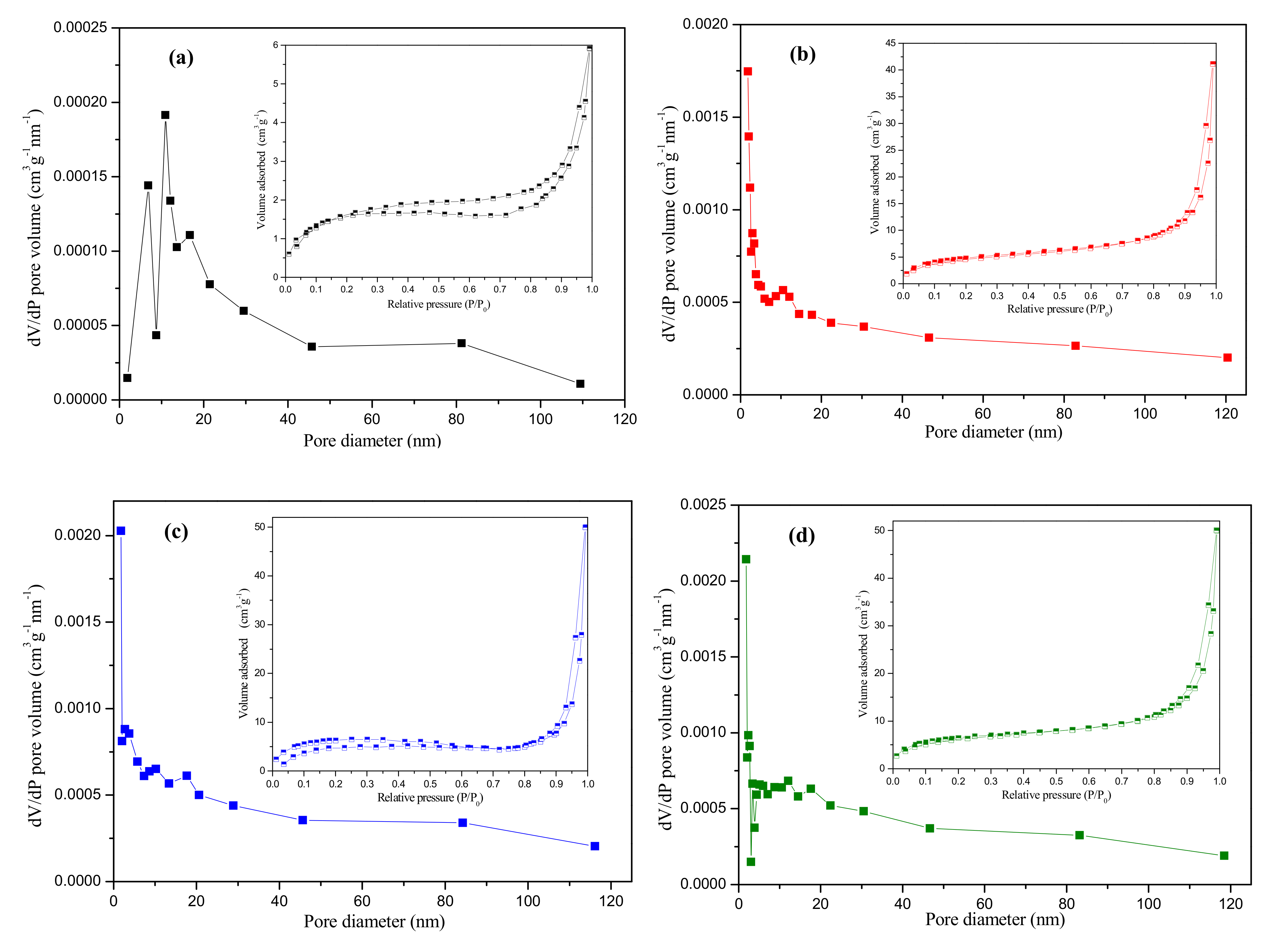
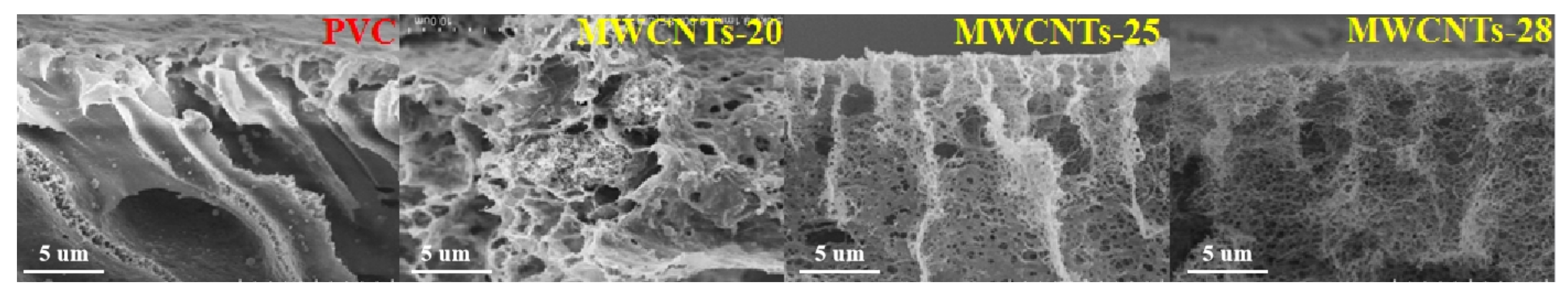
3.1. Membrane Characterization

The surface roughness of the fabricated membranes was characterized by the AFM. As shown in Figure 3, the PVC membrane has the smoothest surface, as indicated by the measured limited surface roughness (from −86.1 nm to 86.1 nm). With the increase in the MWCNT proportion to 20%, 25%, and 28%, the limited surface roughness values increased from −78.9 nm to 91.0 nm, from −103.5 nm to 102.2 nm, and from −386.7 nm to 416.9 nm, respectively. It is obvious that with the increase in the MWCNT proportion, the surface of the composite membranes became rougher. This might be due to the fact that the incorporation of the MWCNTs increased the surface porosity of the membrane (as evidenced by the SEM images).
The pore size distribution and pore volume of the synthesized membranes were characterized by the nitrogen adsorption-desorption isotherms using the pore size analyzer. Figure 4 shows the pore volume as a function of pore diameter for the different membranes. As can be seen from Figure 4a, the PVC membrane contains pores with pore diameter ranging from 1 nm to 120 nm, and the pores with diameters ranging from 5 nm to 20 nm occupied the majority of the total volume. The pore volume of the PVC membrane was only 6 cm3·g−1. By incorporating the MWCNTs into the PVC membranes, the total volume of the pores increased by almost one order of magnitude (from 6 to 50 cm3·g−1). After the incorporation of the MWCNTs, nanometer and sub-nanometer pores (with diameters smaller than 5 nm) emerged, and the volume of those pores account for most of the total pore volume. For MWCNTs-20, MWCNTs-25, and MWCNTs-28 membranes, the diameter of most of the pores was lower than 10 nm (according to Figure 4b–d). The peak value of dV/dD increased from 0.0002 to 0.002 cm3g−1nm−1 after adding the MWCNTs to the membrane. The results indicated that the incorporation of MWCNTs could increase the number of pores and enhance the porosity of the membrane, which was favorable for increasing water flux (permeation) and improving contaminant rejection.
The membrane surface and cross-sectional morphologies were characterized by SEM. Figure 5 shows the surface SEM images of the different membranes. It was clear that the PVC membrane has a relatively dense surface structure, indicating smaller porosity and poorer pore connectivity. In comparison, after incorporating the MWCNTs into the PVC membrane matrices, the surface porosity of the membranes remarkably increased, especially for the MWCNTs-25 and MWCNTs-28 membranes. The enhanced porosity and improved pore connectivity can be evidenced by the membrane cross-sectional SEM images (Figure 6). After the incorporation of the MWCNTs, many nanosized pores emerged and made the sponge-like pores interconnected. The MWCNTs successfully formed skeleton throughout the cross-section of the membrane, and the interconnection of the MWCNTs could facilitate the transport of water molecules.
We measured the breaking strength of the PVC and PVC/MWCNTs membranes to determine their toughness. As shown in Figure 7a, the breaking strength of the pure PVC membrane was 82 cN, whereas the value of the MWCNTs-20, MWCNTs-25, and MWCNTs-28 membranes decreased to 56.6, 30.4, and 22.2 cN, respectively, which was due to the emergence of more pores throughout the structure and the significant increase in the porosity of the membrane (as can be seen from the BET results, Figure 4). The increase in the membrane porosity with the incorporation of the MWCNTs decreased the overall mechanical strength of the membranes and the MWCNT proportion in the composite membrane should be controlled at an appropriate level.
The measured contact angle of the synthesized membranes is shown in Figure 7b. By adding the MWCNTs, the surface of the resulted membranes became more hydrophobic. The contact angle of the PVC membrane was around 40°, whereas the contact angle of the MWCNTs-28 membrane increased to above 120°. The contact angle values of the MWCNTs-20 and MWCNTs-25 membranes were between 40° and 120°. The increased contact angle of the composite membranes was due to the relative hydrophobicity of the MWCNTs. At relatively high MWCNTs loadings, a portion of the MWCNTs migrates onto the surface of the membrane during the fabrication process, resulting in an increase in the membrane surface hydrophobicity (an increase in the contact angle value) of the composite membrane.
Membrane surface zeta potential can be used to characterize the surface charge density. As shown in Figure 7c, all the synthesized membranes had negative zeta potential values, indicating that the surface of all the membranes was negatively charged. More importantly, with the increase in the MWCNTs proportion, the surface zeta potential decreased, meaning that the negative surface charge density increased. The increase in the surface charge density with the increase in the MWCNT proportion can be explained as that increasing the MWCNT proportion enhanced the chance of the MWCNTs to anchor onto (or near) the surface of the membrane. The MWCNTs are carboxylated, and thus they have a negative surface charge. With more MWCNTs migrating onto the membrane surface, the negatively charged functional groups on the membrane surface increased.

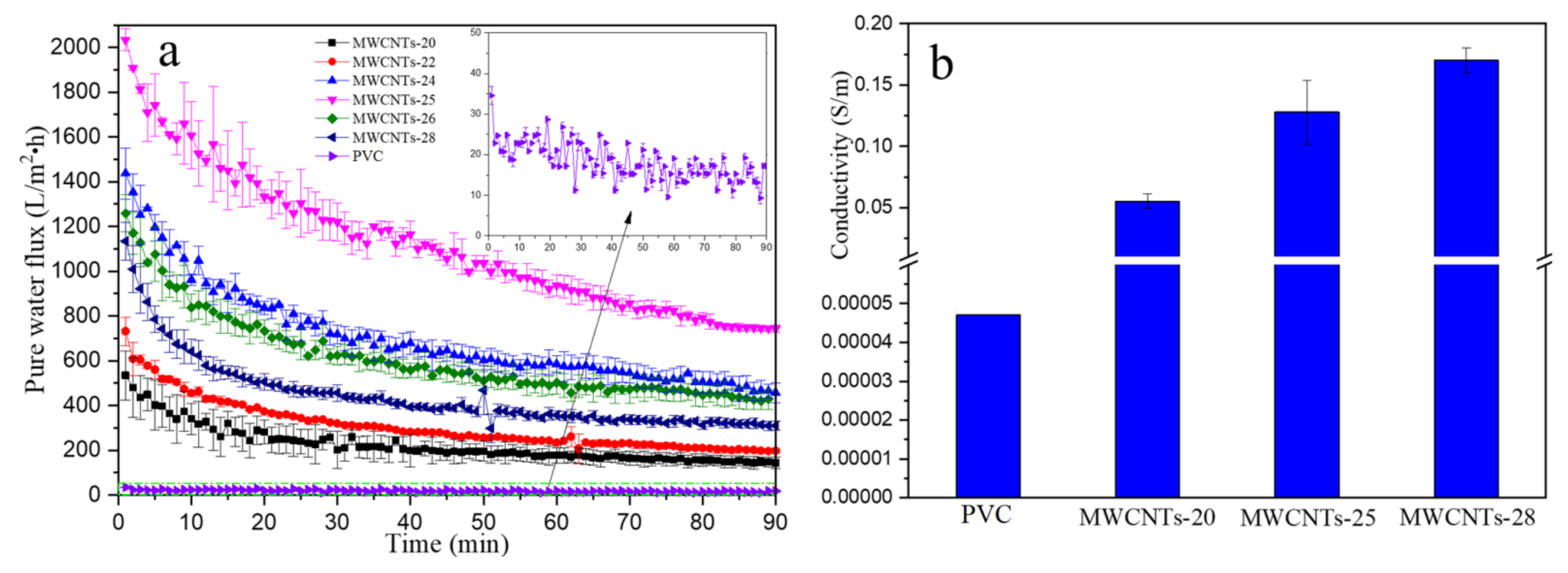
3.2. Effect of MWCNTs Proportion on the Pure Water Flux and Electrical Conductivity of the Composite Membrane

Figure 8a displays the pure water flux of the different membranes under the trans-membrane pressure of 0.15 MPa. It can be seen that the pure water flux of the PVC membrane (control test) was only in the range of 10–20 L/(m2·h), suggesting that the PVC membrane was a dense membrane with a limited amount of pores, as confirmed by the membrane surface SEM images in Figure 5 and Figure 6. The membrane pure water flux significantly increased with the increase in the proportion of MWCNTs. The previous works seldom studied the performance of the membrane with over 20% MWCNTs in water flux, while the current work systematically investigated the effect of a high proportion of MWCNTs in the membrane on the water flux and electrical conductivity. When the MWCNT proportion increased from 20% to 22%, and from 24% and 25%, the highest water flux significantly increased from 533 to 731, and from 1679 and 2033 L/(m2·h), respectively, and the steady pure water flux increased from 143 to 196, and from 327 and 750 L/(m2·h), respectively. However, with the MWCNT proportion further increasing to 26% and 28%, the highest and steady water flux decreased to 1258 and 1133 L/(m2·h), and to 427 and 310 L/(m2·h), respectively. Apparently, 25% was the best proportion for MWCNTs according to the measured water flux results.
The obtained water flux was far higher than that obtained in Yuan’s work (196 L/(m2·h·bar) under the trans-membrane pressure of 0.3 MPa) [24], Ho’s work (26.7 L/(m2·h·bar) under the trans-membrane pressure of 0.3 MPa) [23], Rahimpour’s work (PES-MWCNTs composite membrane with water flux of 150 L/(m2·h·bar) under the trans-membrane pressure of 0.3 MPa) [29], and Farahani’s work (PVDF-MWCNTs composite membrane with water flux of 350 L/(m2·h·bar) under the trans-membrane pressure of 0.1 MPa) [30]. Moreover, the membrane fabrication method used in the present work is simpler, as the use of porogens was not needed, and the energy consumption was less as compared to the cross-linking pressuring filtration method. The results suggest that the MWCNTs exhibited outstanding pore formation performance; the inner nano-pores presented in MWCNTs acted as the pathways for the transport of water molecules. Due to the relatively stable and uniform structure of MWCNTs, the pore diameter in the MWCNTs-PVC membrane would be more uniform. The enclosure space in the inner layer of the PVC membrane matrix would be smaller because the MWCNTs were evenly distributed into the PVC membrane matrix, and thus, the channel connection could be coherent, as revealed in the SEM images in Figure 5 and Figure 6. This is why the increase in the MWCNT proportion significantly increased the pure water flux. However, the excessive proportion of MWCNTs increased the viscosity of the membrane casting solution, which resulted in the formation of a denser and more compact structure, such as the MWCNTs-26 and MWCNTs-28 membranes. A similar phenomenon was also observed previously [24]: the aggravation of a mass of MWCNTs made the membrane structure more compactable, which enhances the hydraulic resistance and path length for the water molecules, and thus, the membrane water permeability was suppressed.
Figure 8b depicts the electrical conductivity of the MWCNTs/PVC composite membranes. The electrical conductivity increased by three orders of magnitude when the MWCNTs were incorporated into the PVC matrices. With the MWCNT proportion increasing to 20%, 25%, and 28%, the conductivity increased to 0.055, 0.128, and 0.170 S/m, respectively. The introduced conductive MWCNTs acted as the channels for the electrons to migrate; thus, the rise in the proportion of MWCNTs increased the density of current pathways in the membrane matrices. The prepared MWCNTs-PVC composite membrane in the present work exhibited comparable or better conductive properties as compared with the reported MWCNTs-based conductive membranes. For instance, in Ho’s work [23], the nascent 21.8% MWCNT membrane demonstrated an electrical conductivity of 1.56 × 10⁻² S/m, and the value for the PSF/PANI/MWCNTs composite membrane prepared in Yuan’s work [24] was only 2.0 × 10⁻⁵ S/m. Hence, the membrane fabricated in the present work had higher water permeability as well as better electrical conductivity. The incorporated MWCNTs played a bifunctional role: the networks as well as the inner channels of the nanotubes were used to transport water molecules (more channels for water transport are formed with the incorporation of the MWCNTs into the membrane matrix), and the skeleton of the nanotubes was utilized to transfer the electrons. The MWCNT networks were successfully established throughout the PVC membrane matrix. Considering the two indicators of water flux and conductivity, 25 wt % of MWCNTs was the best in terms of the overall performance.

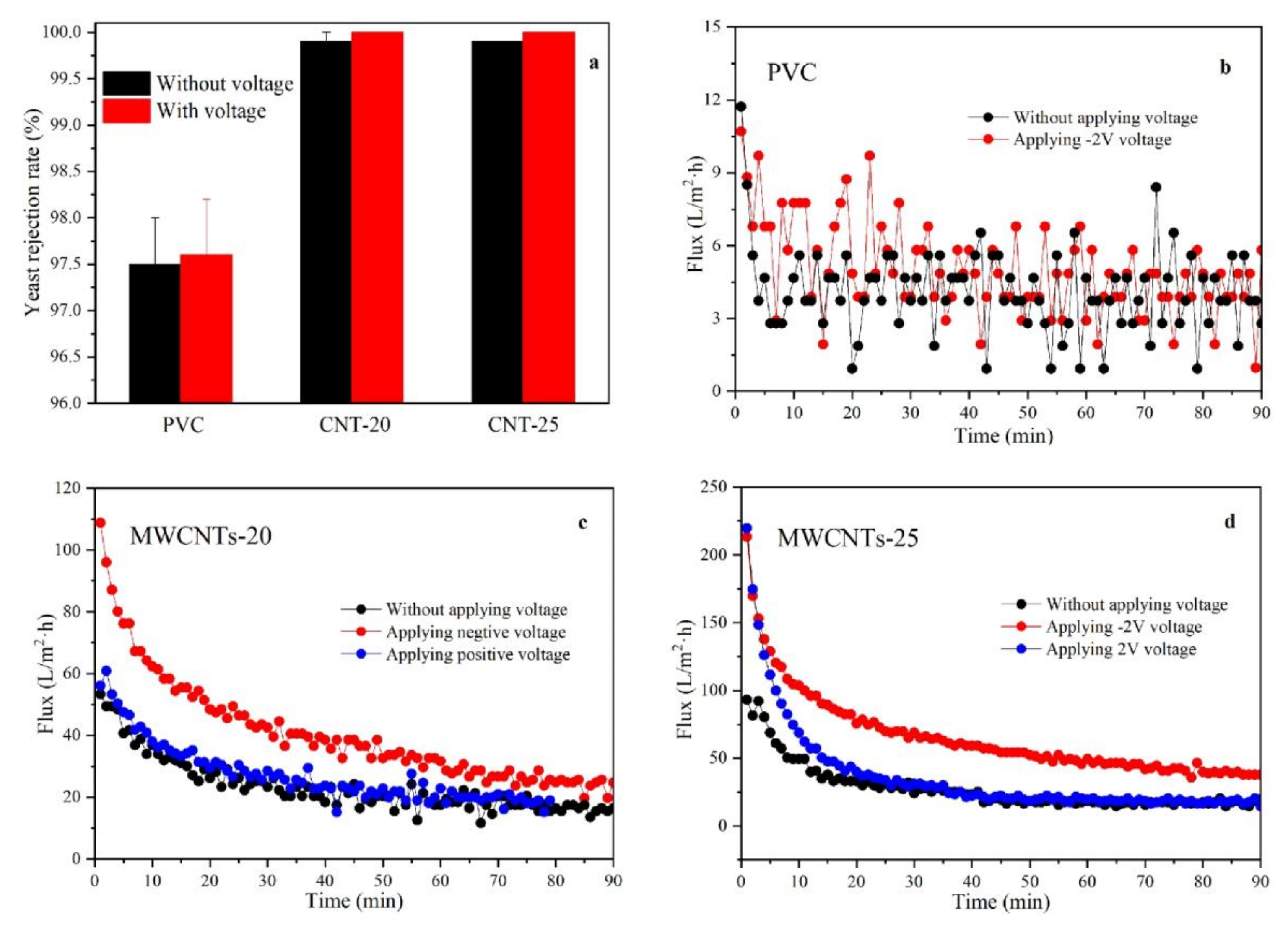
3.3. Rejection and Electrically Enhanced Antifouling Performance

The MWCNTs/PVC conductive membranes were used to filtrate the 3 g/L yeast solutions. The experiments included five parallel tests for each membrane either without or with an external electric field. As shown in Figure 9a, the yeast rejection of the PVC membrane was 97.5% and 97.6% without and with the electrical field, respectively; those of the MWCNTs-20 and MWCNTs-25 membranes were over 99.8% no matter whether the electrical field was applied or not, with the standard deviation lower than 0.2%. The electrical field had negligible influence on the membrane rejection towards yeast, suggesting that the molecular size of the yeast was larger than the pore size of the prepared membranes. The noticeable increment in the membrane yeast rejection after incorporating the MWCNTs was due to a more uniform pore structure being formed. The diameter of the nanotubes was uniform, and the skeleton formed by the MWCNTs was stable; thus, the overall membrane rejection further increased.
Although the electrical field showed limited influence on the membrane rejection, it played an important role in enhancing the antifouling property of the membranes. Figure 9b shows the antifouling performance of the PVC membrane in the filtration of yeast solution with and without the assistance of the electrical field. The membrane water flux was stable and below 10 L/(m2·h) no matter whether the electrical field was added or not, suggesting that the PVC membrane is an insulator and that the electrical field had negligible influence on the membrane filtration performance. The surface properties of the PVC membrane remained unaffected by the applied electrical field; thus, the interaction between the membrane surface and the foulant was not influenced by the electrical field and the water flux was unchanged.
Figure 9c,d demonstrates the electro-enhanced antifouling performance of the MWCNTs-20 and MWCNTs-25 membranes. When no extra electrical voltage was added, the filtrate flux sharply decreased from 60 L/(m2·h) to below 20 L/(m2·h) for the MWCNTs-20 membrane and decreased from 90 L/(m2·h) to 20 L/(m2·h) for the MWCNTs-25 membrane. Then, we applied an external negative voltage of −2 V to the two membranes, and the initial highest filtrate flux sharply increased to 110 L/(m2·h·bar) for the MWCNTs-20 membrane and to 220 L/(m2·h) for the MWCNTs-25 membrane. As the filtration test proceeded, the filtrate flux of the two membranes decreased to 27 L/(m2·h) and 45 L/(m2·h), respectively. Subsequently, we investigated the flux variation after applying the positive voltage of 2 V on the two membranes, and found that the change in the filtrate flux was similar to that when no electrical field was applied, which indicated that due to the negatively charged surface of the yeast, the yeast particles can quickly deposit onto the surface of the membranes. It can be calculated from the results that when adding the external negative voltage of −2 V, the stabilized filtrate flux increased by about 35% and 125% for the MWCNTs-20 and MWCNTs-25 membranes, respectively, indicating that the negative voltage was effective in minimizing the membrane (yeast) fouling. Another interesting phenomenon was observed during the electro-assisted antifouling tests: with the addition of the external electrical field, tiny gas bubbles continuously discharged from the effluent of permeated solution. A possible reason for this phenomenon is the electro-production of H2 and O2 gases, which were generated on the surface or in the inner pores of the membranes.
The antifouling mechanism of the MWCNTs/PVC composite membrane in the filtration of yeast solution was attributed to the synergism of electrostatic repulsion and in situ aeration exclusion. During the cross-flow filtration process, the electrostatic repulsion between the negatively charged yeast particles and the surface of the conductive membrane was enhanced due to the presence of the electrical field. The enhanced electrostatic repulsion effectively prevents the foulants from depositing onto the membrane surface and/or blocking the pores of the membrane. This is why the initial filtrate flux of MWCNTs/PVC composite membranes with an electrical field was two times higher than that without an electrical field. After a certain period of time, the resistance for water molecules passing through the foulant layer increased, and some tiny foulants formed by weak negatively charged particles entered the pores, causing a decrease in filtrate flux. The micro gas bubbles produced from the electrochemical reaction could prevent those particles from entering the membrane pores or accelerate the transfer of these particles to the permeate solution, so that the filtrate flux could still maintain at a relatively high level. Specifically, the gas microflows arising on the conductive membrane surface could hinder the foulant (and/or particle) adsorption or deposition on the membrane surface, which has been discussed in a previous study [31]. This can explain that the higher filtrate flux can be maintained in a long-term filtration test for the MWCNTs/PVC composite membranes. Figure 10 displays the images of the MWCNTs/PVC membranes after the filtration tests. It is clear that without the assistance of external negative voltage, a compact fouling layer was formed on the surface of the membrane. However, when −2 V of voltage was applied, a relatively loose fouling layer was deposited onto the anode, and the surface of the MWCNTs/PVC membrane cathode was relatively clean. Hence, the proposed anti-fouling mechanism is supported by the images.
From a practical point of view, in situ aeration is an effective and environmentally friendly way of performing an online cleaning process for the fouling membrane. It can eliminate the use of chemical reagents for membrane cleaning, as well as avoid the secondary wastewater generation and treatment. In addition, due to the high electrical conductivity of the MWCNTs/PVC composite membranes, the applied external voltage used in the current study was 2 V (1 cm), which is lower than in the previous works [23], which used 5–30 V; thus, the required energy consumption is substantially reduced. To obtain the energy cost, we calculated the power consumption when we used the conductive membrane. The applied voltage is 2 V, and the corresponding current is about 67 mA, so the power consumption per hour will be 1.34 × 10⁻⁴ kWh. The relatively simple fabrication process of the conductive membrane in this study is another advantage. Given the high water flux and effective anti-fouling of the electrically assisted membrane filtration process, it has the potential to emerge as a novel strategy for advanced membrane processes in water and wastewater treatment.

4. Conclusions

In this study, electrically conductive membranes were fabricated by using PVC as the polymeric material (membrane matrices) and MWCNTs as the inorganic nanomaterial (conductive dopant). The fabricated MWCNTs/PVC composite membranes had significantly enhanced porosity. The inter-connected pores formed upon the addition of the MWCNTs. As a result, the water flux of the MWCNTs/PVC composite membranes was higher than the pure PVC membrane. The MWCNTs/PVC composite membranes had higher surface charge density (more negative zeta potential) and higher electrical conductivity. The membrane antifouling tests showed that both the initial water flux and the stable water flux of the MWCNTs/PVC composite membranes were higher than that of the pure PVC membrane. The enhanced anti-fouling properties of the MWCNTs/PVC composite membranes can be explained by the synergism of electrostatic repulsion and in situ aeration exclusion. The current study presents a facile and effective way of designing conductive and anti-fouling membranes for water and wastewater treatment and provides a promising way for the development of robust membrane systems. As conductive filtration membranes are effective for eliminating the use of chemical reagents for membrane cleaning and avoiding secondary wastewater generation, the results from this study can serve as guidance for the future design of robust, high-performance conductive membranes with enhanced anti-fouling properties.

Author Contributions

Investigation, X.C., J.G., and Y.S.; writing—original draft preparation, X.C. and Y.G.; writing—review and editing, M.Q.; supervision, R.H.; funding acquisition, R.H. All authors have read and agreed to the published version of the manuscript.

Funding

This research was funded by the National Natural Science Foundation of China (grant no. 51978262 and 52170108), the Natural Science Foundation of Hebei Province (grant no. E2021502002), and the Fundamental Research Funds for the Central Universities (grant no. 2019MS128).

Institutional Review Board Statement

Not applicable.

Informed Consent Statement

Not applicable.

Data Availability Statement

The data presented in this study are available on request from the corresponding author.

Conflicts of Interest

The authors declare no conflict of interest.

References

  1. Werber, J.R.; Osuji, C.O.; Elimelech, M. Materials for next-generation desalination and water purification membranes. Nat. Rev. Mater. 2016, 1, 16018. [Google Scholar] [CrossRef]
  2. Ang, W.L.; Mohammad, A.W.; Hilal, N.; Leo, C.P. A review on the applicability of integrated/hybrid membrane processes in water treatment and desalination plants. Desalination 2015, 363, 2–18. [Google Scholar] [CrossRef]
  3. Park, H.B.; Kamcev, J.; Robeson, L.M.; Elimelech, M.; Freeman, B.D. Maximizing the right stuff: The trade-off between membrane permeability and selectivity. Science 2017, 356, eaab0530. [Google Scholar] [CrossRef] [Green Version]
  4. Zheng, J.; Li, M.; Yu, K.; Hu, J.; Zhang, X.; Wang, L. Sulfonated multiwall carbon nanotubes assisted thin-film nanocomposite membrane with enhanced filtrate flux and anti-fouling property. J. Membr. Sci. 2017, 524, 344–353. [Google Scholar] [CrossRef]
  5. Ma, J.; Guo, X.; Ying, Y.; Liu, D.; Zhong, C. Composite ultrafiltration membrane tailored by MOF@ GO with highly improved water purification performance. Chem. Eng. J. 2017, 313, 890–898. [Google Scholar] [CrossRef] [Green Version]
  6. Gao, W.; Liang, H.; Ma, J.; Han, M.; Chen, Z.-L.; Han, Z.-S.; Li, G.-B. Membrane fouling control in ultrafiltration technology for drinking water production: A review. Desalination 2011, 272, 1–8. [Google Scholar] [CrossRef]
  7. Katsoufidou, K.; Yiantsios, S.; Karabelas, A. A study of ultrafiltration membrane fouling by humic acids and flux recovery by backwashing: Experiments and modeling. J. Membr. Sci. 2005, 266, 40–50. [Google Scholar] [CrossRef]
  8. Asatekin, A.; Kang, S.; Elimelech, M.; Mayes, A.M. Anti-fouling ultrafiltration membranes containing polyacrylonitrile-graft-poly (ethylene oxide) comb copolymer additives. J. Membr. Sci. 2007, 298, 136–146. [Google Scholar] [CrossRef]
  9. Liu, L.; Liu, J.; Bo, G.; Yang, F.; Crittenden, J.; Chen, Y. Conductive and hydrophilic polypyrrole modified membrane cathodes and fouling reduction in MBR. J. Membr. Sci. 2013, 429, 252–258. [Google Scholar] [CrossRef]
  10. Liu, J.; Tian, C.; Xiong, J.; Wang, L. Polypyrrole blending modification for PVDF conductive membrane preparing and fouling mitigation. J. Colloid Interface Sci. 2017, 494, 124–129. [Google Scholar] [CrossRef]
  11. Fan, X.; Zhao, H.; Liu, Y.; Quan, X.; Yu, H.; Chen, S. Enhanced Permeability, Selectivity, and Antifouling Ability of CNTs/Al2O3 Membrane under Electrochemical Assistance. Environ. Sci. Technol. 2015, 49, 2293–2300. [Google Scholar] [CrossRef]
  12. Wang, K.; Xu, L.; Li, K.; Liu, L.; Zhang, Y.; Wang, J. Development of polyaniline conductive membrane for electrically enhanced membrane fouling mitigation. J. Membr. Sci. 2019, 570, 371–379. [Google Scholar] [CrossRef]
  13. Tiwari, P.; Janas, D.; Chandra, R. Self-standing MoS2/CNT and MnO2/CNT one dimensional core shell heterostructures for asymmetric supercapacitor application. Carbon 2021, 177, 291–303. [Google Scholar] [CrossRef]
  14. Zhang, Z.; Huang, G.; Li, Y.; Chen, X.; Yao, Y.; Ren, S.; Li, M.; Wu, Y.; An, C. Electrically conductive inorganic membranes: A review on principles, characteristics and applications. Chem. Eng. J. 2022, 427, 131987. [Google Scholar] [CrossRef]
  15. Liu, J.; Liu, L.; Gao, B.; Yang, F. Cathode membrane fouling reduction and sludge property in membrane bioreactor integrating electrocoagulation and electrostatic repulsion. Sep. Purif. Technol. 2012, 100, 44–50. [Google Scholar] [CrossRef]
  16. Li, N.; Liu, L.; Yang, F. Highly conductive graphene/PANi-phytic acid modified cathodic filter membrane and its antifouling property in EMBR in neutral conditions. Desalination 2014, 338, 10–16. [Google Scholar] [CrossRef]
  17. Liu, L.; Liu, J.; Gao, B.; Yang, F.; Chellam, S. Fouling reductions in a membrane bioreactor using an intermittent electric field and cathodic membrane modified by vapor phase polymerized pyrrole. J. Membr. Sci. 2012, 394, 202–208. [Google Scholar] [CrossRef]
  18. Liu, H.; Zhang, G.; Zhao, C.; Liu, J.; Yang, F. Hydraulic power and electric field combined antifouling effect of a novel conductive poly (aminoanthraquinone)/reduced graphene oxide nanohybrid blended PVDF ultrafiltration membrane. J. Mater. Chem. A 2015, 3, 20277–20287. [Google Scholar] [CrossRef]
  19. Duan, W.; Ronen, A.; Walker, S.; Jassby, D. Polyaniline-coated carbon nanotube ultrafiltration membranes: Enhanced anodic stability for in situ cleaning and electro-oxidation processes. ACS Appl. Mater. Interface 2016, 8, 22574–22584. [Google Scholar] [CrossRef]
  20. de Lannoy, C.; Jassby, D.; Davis, D.; Wiesner, M. A highly electrically conductive polymer–multiwalled carbon nanotube nanocomposite membrane. J. Membr. Sci. 2012, 415, 718–724. [Google Scholar] [CrossRef]
  21. Duan, W.; Ronen, A.; de Leon, J.V.; Dudchenko, A.; Yao, S.; Corbala-Delgado, J.; Yan, A.; Matsumoto, M.; Jassby, D. Treating anaerobic sequencing batch reactor effluent with electrically conducting ultrafiltration and nanofiltration membranes for fouling control. J. Membr. Sci. 2016, 504, 104–112. [Google Scholar] [CrossRef] [Green Version]
  22. Zhang, Q.; Vecitis, C.D. Conductive CNT-PVDF membrane for capacitive organic fouling reduction. J. Membr. Sci. 2014, 459, 143–156. [Google Scholar] [CrossRef]
  23. Ho, K.; Teow, Y.; Mohammad, A.W.; Ang, W.; Lee, P. Development of graphene oxide (GO)/multi-walled carbon nanotubes (MWCNTs) nanocomposite conductive membranes for electrically enhanced fouling mitigation. J. Membr. Sci. 2018, 552, 189–201. [Google Scholar] [CrossRef]
  24. Yuan, X.-S.; Guo, Z.-Y.; Geng, H.-Z.; Rhen, D.S.; Wang, L.; Yuan, X.-T.; Li, J. Enhanced performance of conductive polysulfone/MWCNT/PANI ultrafiltration membrane in an online fouling monitoring application. J. Membr. Sci. 2019, 575, 160–169. [Google Scholar] [CrossRef]
  25. Masoumi, S.; Miroliaeia, A.R.; Jafarzadeh, Y. Preparation and characterization of MWCNT-COOH/PVC ultrafiltration membranes to use in water treatment. Adv. Environ. Technol. 2018, 2, 95–105. [Google Scholar]
  26. Demirel, E.; Zhang, B.; Papakyriakou, M.; Xia, S.; Chen, Y. Fe2O3 nanocomposite PVC membrane with enhanced properties and separation performance. J. Membr. Sci. 2017, 529, 170–184. [Google Scholar] [CrossRef] [Green Version]
  27. Zhang, Y.; Tong, X.; Zhang, B.; Zhang, C.; Zhang, H.; Chen, Y. Enhanced permeation and antifouling performance of polyvinyl chloride (PVC) blend Pluronic F127 ultrafiltration membrane by using salt coagulation bath (SCB). J. Membr. Sci. 2018, 548, 32–41. [Google Scholar] [CrossRef]
  28. Coasne, B.; Gubbins, K.E.; Pellenq, R.J.M. A grand canonical Monte Carlo study of adsorption and capillary phenomena in nanopores of various morphologies and topologies: Testing the BET and BJH characterization methods. Part. Part. Syst. Charact. 2004, 21, 149–160. [Google Scholar] [CrossRef]
  29. Rahimpour, A.; Jahanshahi, M.; Khalili, S.; Mollahosseini, A.; Zirepour, A.; Rajaeian, B. Novel functionalized carbon nanotubes for improving the surface properties and performance of polyethersulfone (PES) membrane. Desalination 2012, 286, 99–107. [Google Scholar] [CrossRef]
  30. Farahani, M.H.D.A.; Vatanpour, V. A comprehensive study on the performance and antifouling enhancement of the PVDF mixed matrix membranes by embedding different nanoparticulates: Clay, functionalized carbon nanotube, SiO2 and TiO2. SEP Purif. Technol. 2018, 197, 372–381. [Google Scholar] [CrossRef]
  31. Yang, Y.; Li, J.; Wang, H.; Song, X.; Wang, T.; He, B.; Liang, X.; Ngo, H.H. An electrocatalytic membrane reactor with self-cleaning function for industrial wastewater treatment. Angew. Chem. Int. Ed. 2011, 50, 2148–2150. [Google Scholar] [CrossRef]
Figure 1. Schematic illustration of the synthesis of the different membranes.
Coatings 11 01548 g001
Figure 2. Schematic illustration of the membrane performance (membrane water flux, rejection, and antifouling) testing setup.
Coatings 11 01548 g002
Figure 3. Surface AFM images of the fabricated membranes of PVC, MWCNTs-20, MWCNTs-25, and MWCNTs-28 (from top to bottom, roughness, top view, and perspective view).
Coatings 11 01548 g003
Figure 4. Pore diameter as a function of pore volume of (a) PVC, (b) MWCNTs-20, (c) MWCNTs-25, and (d) MWCNTs-28 membranes. The insets showed the nitrogen adsorption–desorption isotherms.
Coatings 11 01548 g004
Figure 5. Surface SEM images of PVC, MWCNTs-20, MWCNTs-25, and MWCNTs-28 membranes.
Coatings 11 01548 g005
Figure 6. Cross-sectional SEM images of PVC, MWCNTs-20, MWCNTs-25, and MWCNTs-28 membranes.
Coatings 11 01548 g006
Figure 7. Breaking strength (23 cm × 16 cm area) (a), contact angle (b), and zeta potential (c) of PVC, MWCNTs-20, MWCNTs-25, and MWCNTs-28 membranes.
Coatings 11 01548 g007
Figure 8. (a) Pure water flux (under 0.15 MPa of pressure) and (b) electrical conductivity of the membranes with different MWCNT proportions.
Coatings 11 01548 g008
Figure 9. Yeast rejection tests using different membranes (a). Water flux variation vs. time using PVC membrane (b), MWCNTs-20 membrane (c), and MWCNTs-25 (d). Both the water flux values without and with applying voltage are shown.
Coatings 11 01548 g009
Figure 10. Antifouling performance of MWCNTs-25 membrane without and with electro-assistance.
Coatings 11 01548 g010
Table 1. The ingredient of membrane casting solutions.
Membrane SamplesNMP (mL)PVC (g)PEG (g)MWCNTs (g)MWCNTs Proportion (%)
PVC4041.600
MWCNTs-2040300.7520%
MWCNTs-22402.6600.7522%
MWCNTs-24402.3800.7524%
MWCNTs-25402.2500.7525%
MWCNTs-26402.1400.7526%
MWCNTs-28401.9300.7528%
Publisher’s Note: MDPI stays neutral with regard to jurisdictional claims in published maps and institutional affiliations.

