1. Introduction
The technical condition of the wheelset of a platform and the process of interaction between the contact tread surface and the rail, which is accompanied by large dynamic loads, have significant impacts on the efficiency and safety of freight car operation [
1,
2,
3,
4,
5,
6,
7]. The range of changes in a cyclic load directly depends on the intensity of changes in the design profile of the wheel (such as abrasion challenges), operating modes (speeding up and braking) and the sum moments of forces that occur during different periods of wheel contact [
8,
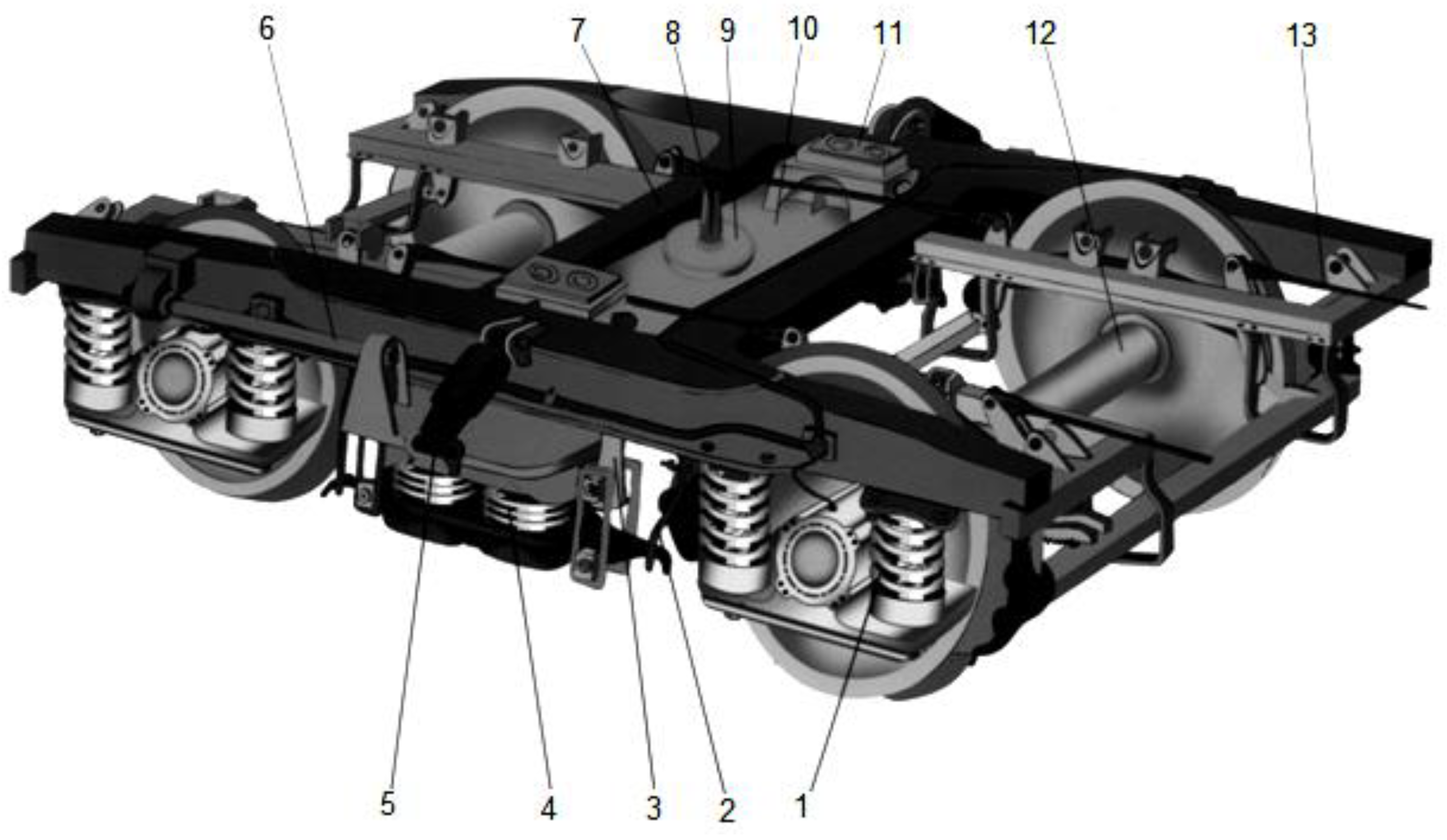
9]. The durability of the wheelset of a railway car largely depends on the dynamic and strength characteristics of the wheel, as well as on the design features and recovery material of the car bogie (
Figure 1).
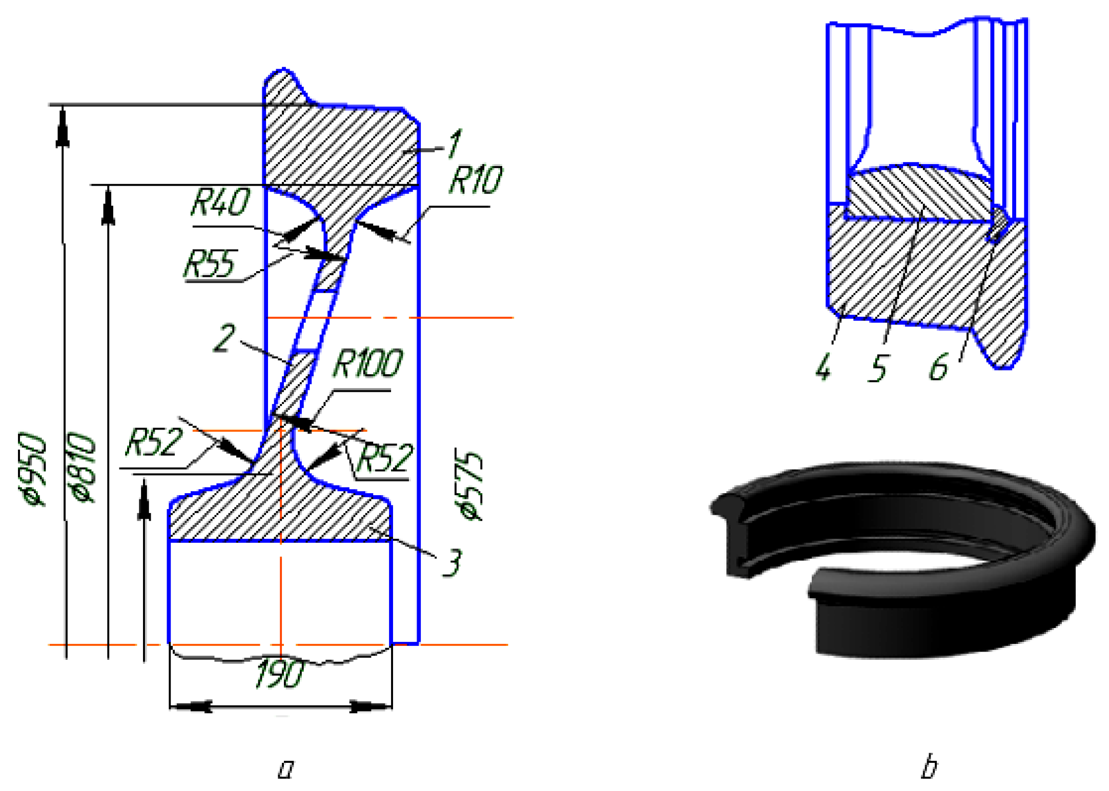
According to their structural elements, the wheels of railway cars may be divided into tyreless (one-piece) and tyred (composite) wheels (
Figure 2a,b).
Researchers Dumpala R, Chandran M., Rao M.S.R., Buinusov A.P., Glazunov D.V., Myamlin S.V., and Panasenko V. Ya. [
10,
11,
12] have established that solid-rolled wheels have several significant advantages in comparison to tyred ones. When a car is running, the tread surfaces of the wheels are constantly in contact with the rails and are subjected to intense dynamic loads (
Pd and
Pc), which are not constant over time. Simultaneously, the wheels come into contact with the rails with a small surface (about 2–2.5 cm
2), thus transmitting large static and dynamic loads (up to 110 kN). As a result, the contact zone of the wheel and rail undergoes significant deformations and large contact stresses (
σk), causing the appearance of fatigue cracks on the tread surface of the wheel.
An analysis of the work of S. Niederhauser and S. Cantini [
12,
13] in the field of repair of railway wheels of rolling stock and the restoration of various equipment has allowed us to conclude that the modern scientific and industrial base of rolling stock needs to develop new and effective ways to restore the rolling surfaces of car wheels.
Experiencing statistically significant shock and dynamic loads causes the elements of the wheelset to intensively wear out [
13,
14,
15]. Defects that are formed as a result of wear have a wide range of structural and external changes (
Table 1). Such defects in the wheelsets of railway cars reduce their efficiency and may be dangerous and require repair and restoration [
16,
17,
18,
19].
2. Statement of the Scientific Problem in the Efficiency of Railway Car Operation
Currently, there is no systematic approach to substantiating the reasons for the formation of such heterogeneous defects. In their research, scientists S. V. Myamlin and M. S. R. Rao [
17,
18] ambiguously interpreted the physical meaning of the defect formation process. The classical analysis and strength calculations of the wheel were reduced to the study of the acting forces applied to the equilibrium system, considering the static characteristics of the wheel size and steel grade. The defect, as a consequence of fatigue wear (cracks, breaks, destruction, chipping, fractures, etc.), was investigated, but the original cause of its formation was not. However, this calculation method did not consider the effective moments of forces at different time intervals in different operating modes, as well as the effect of changing the wheel profile and the deviation of the contact spot from the axial trajectory of movement.
The works of M.M. Machnev, A.E. Tsikunov, A.F. Bogdanov, D.P. Kononov, Yu. V. Gomonets, A.O. Kolomeets, A.S. Kochetkov, and others [
19,
20,
21,
22,
23,
24] were devoted to the study of wheelset defects. These studies were aimed at intensive wear (depending on the conditions of friction and operation), the condition of the track, and the properties of the metal, and it was found that the most dangerous defects occurred on the rolling surface, since the surface of the rolling wheel wears out by about 5–8 mm (rolled) during the year and a large amount of car uncoupling is associated with the presence of wheel damage caused by defects of braking origin.
The fatigue dynamic type of wear destroys the friction surfaces of a wheel under increased stresses and loads. At the same time, macro-geometric deviations accelerate the development of contact fatigue defects, thereby accelerating the fatigue life of the car wheel. Additionally, the stresses at which destruction occurs may be below both the limit of contact fatigue strength and the limit of elasticity.
Dynamic wear is the result of the intensive destruction of the surface layers of metal at the molecular level, which are under special stress conditions. With this type of destruction, the time required by the process that causes metal fatigue exceeds the time of other processes occurring on friction surfaces, so the process of fatigue failure becomes predominant.
These authors listed the operational factors that affect the appearance of the defect, considered it as a fact that had already happened. The authors’ reasoning was based on the well-known laws of friction and wear at acting forces and moments. Additionally, all researchers classify types of wear and study them separately from each other. However, we believe that the wear process is not just subject to the laws of friction under shock loads. It is necessary to consider how the wheel contact spot changes in a given time interval and how stress is formed in the metal structure when wear deviates from the design geometry indicated in its drawings. Another important factor is the application of a systematic approach to the study of wheel durability with different types of defects on the same cross-sectional area. Consequently, the degree of the influence of dynamic forces on the heterogeneous defects of one wheel vary in a given progression.
Thus, to develop design and technological measures aimed at improving the efficiency, safety of operation, and long-term operation of wheelsets, it is necessary to establish a causal relationship between changes in the physical and mechanical properties of wheel materials and the principles of dynamic load redistribution.
Defects in the wheel sets of railway cars and the causes of their occurrence are shown in
Table 1. These data were obtained at the car repair depot of the branch of the South Ural Railway in Petropavlovsk. The following methods were used to collect data:
- (1)
Visual inspection of car wheel defects.
- (2)
Control of geometric characteristics with special gauges and templates.
- (3)
Evaluation of the car profile by a profiler.
- (4)
Application of vibration sensors in the operation of cars.
- (5)
Non-destructive testing of fatigue stresses by the eddy current method and the method of magnetic memory of metal.
We carried out an in-depth analysis of the defect cards of the car repair depot of “Temirzholy” JSC of Kazakhstan.
A promising direction for improving the wear resistance of the rolling surface of railway wheels is the surfacing of metal with the subsequent mechanical processing of the surfaced part to obtain a specified size and working profile. On the worn surface of the rolling or ridge of a rotating wheel, a reduction metal is deposited by sequentially applying annular rollers from the base of the ridge to its top. The wheel is then cooled and machined. The surfacing process leads to the thermal hardening of the formed surface layer, which creates problems when machining the skating surface and does not allow one to obtain a rolling surface with a given accuracy (both in the radius from the axis of rotation of the wheel to its rolling surface and in the shape of the working profile) and the cleanliness of the treated surface after machining. This disadvantage can be eliminated by surfacing shock-resistant and wear-resistant materials with the heat treatment of wheel pairs in the form of annealing or normalization after surfacing.
A fundamental change in the multicomponent composition of a coating material allows for a radical increase in coatings’ adhesion, density, and mechanical and anticorrosive properties.
In many case, issues of increasing anticorrosive properties are practically based on the use of chemical reagents or paint coatings [
25]. However, this is only possible for parts that are stationary. For parts subject to dynamic cyclically varying loads, it has been proposed to increase corrosion resistance by modifying the surface with coatings.
Table 1 describes visible mechanical damage and external signs characterizing operational parameters. These visible defects have already occurred, and their causes have been established via analysis and the calculation of classical force or strength while considering the moments and dynamics of cyclically acting forces. The authors of this paper set the much more difficult task of solving a scientific problem. We decided it was necessary to investigate the causal relationship between the change in the phase structure of the material and the formation of fatigue stresses before a defect appears. It was assumed that the study of the physical process of structure degradation and the formation of stress concentration zones precedes the appearance of any physical wear. By establishing this dependence, it was possible to more accurately predict the area of defect formation and the moment of its occurrence, i.e., to predict the life of the part without waiting for the appearance of a visible defect.
Due to the physical features of the coating formation process, as the layer thickness increases, internal stresses also increase and disrupt the process of adhesion to the substrate. The low ductility of self-fluxing alloys and the high coefficient of linear expansion create a risk of cracking of the coating during cooling. If the base metal is carbon steel with a content of 0.25% C, ferritic corrosion-resistant steel of the Cr25Ni13 type, austenitic corrosion-resistant steel of the 12Cr18Ni9T and Cr18Ni10T types, or other steel in which the cooling excludes martensitic transformations, cooling the products after fusing the thin coating does not require any additional measures.
The study of the hardness of the sprayed parts made at Petropavlovsk RMZ JSC, Remplasma LLP, and observations of the repair stock showed a low coating hardness and heterogeneity of the layer when using the PN68Ni21C5R, GOST 21448-75, and TU 14-1-3997-85 powders. In order to increase the hardness and adhesion, as well as possibly reduce the number of pores and cracks, of the sprayed layer, it was decided to introduce a special powder composition into the plasma jet.
Two variants were used as powder materials.
The first was a self-fluxing powder B. 03 PR-Mo73Cr16C3R3 (NRS-47-52), NiSg-Fe+50 (80)%Sg3C2 based on nickel.
The second one was 15Cr17N12V3F (innovative patent No.21589 “Plasma coating of metals”).
As a result, three variants of the powder mixture were adopted for the study of the restored wheelsets: plasma spraying with a self-fluxing powder composition of FSH-Fe+50 (80)%Sg3C2 based on nickel; plasma spraying in the environment of protective gases PN68Ni21C5R, GOST 21448-75, and TU 14-1-3997-85; and plasma spraying with the powder composition of 15Ni17N12V3F.
Consequently, this formed a scientific problem regarding the need to develop a systematic approach to the study of the cause and the determination of the dependence of the change in the wear of the wheel contact surface on dynamic loads and the intensity of the deviation of the contact spot from the axis of the car’s trajectory on curved sections [
26].
The authors made a theoretical assumption that the wear rate of the wheelset was significantly affected by the recovery material due to the redistribution of moments of forces and structural gaps in the coupling of the axle box, with the deviation of the contact spot of the design tread surface profile coming from the axial trajectory of movement [
27].
Our scientific hypothesis was that the definition of the boundaries of the area of the deviation of the wheel contact spot and the valid coefficient of deviation from axial trajectory would improve wheelset TOI, develop a constructive technological control system of wheelset radial self-adjustment, and monitor the effective pressure of the wheel flange on the curved sections of the track.
3. Setting Up an Experiment to Study the Optimal Modes of Laser-Plasma Recovery
The multifactorial planning of the experiment was adopted in the work. First of all, it was necessary to choose a criterion, i.e., a parameter by which the object under study was to be evaluated and which bound factors into a mathematical model.
Thus, we accepted the following variables as criteria for optimizing plasma spraying: y
1 was designated as the hardness of the sprayed layer, y
2 was designated as the tension, and y
3 was designated as the adhesion (characterizing the strength and depth of adhesion). Before constructing the matrix of sprayed experiments, ten factors were selected: x
1, x
2, x
3, x
4, … x
10, each of which varied at two levels: max and min. The list of considered factors is presented in
Table 2. The matrix of sprayed experiments is presented in an expanded form in
Table 3. Next, plasma spraying was performed
n number of times in the modes of variable values of x
1, x
2, x
3, x
4, … x
10 at two levels of max and min (
Appendix A;
Table A1).
The test was carried out for one criterion (just the spraying distance—x10), and we built a polynomial model that maximally describes the dependence of y on this criterion. Then, these values of the criterion x10 and y were substituted into a general, already linear model. The equation of dependence of y1 (hardness) on x10 (spraying distance) was as follows:
y1 = −0.0894x2 + 1.0979x + 48.213—(equation of polynomial dependence of the second degree). The coefficient of determination R2 = 0.9949, close in value to 1, shows that the chosen model was adequate.
After that, a correlation matrix was constructed (showing how strong the dependence of y
1 on the other signs was: x
1–x
10) (
Appendix A;
Table A2).
As can be seen from this matrix, the relationship of hardness with these characteristics was quite high (the minimum was 0.22). The greatest relationship was observed between the resulting feature and the criteria x
1, x
2, x
8, and x
10. Similarly, a connection was established between y
2 and y
3 from the formative factors x
1–x
10 (
Appendix A;
Table A2). The equation of the dependence of y
2 (intensity) on x
10 (spraying distance) was as follows:
The equation of dependence of y
3 (adhesion) on x
10 (spraying distance) was as follows:
The authors established that the hardness, energy strength, and adhesion of the coating, in addition to the main operating parameters (voltage, current, rotation speed of the part, etc.), are significantly influenced by indirect factors such as the mixing coefficient, spraying distance, and multi-component structure. For a deeper analysis, it was necessary to consider many factors, but the dispersion analysis showed that only ten had main influence (
Table 2). Previous studies have shown that with an increase in the spraying distance of more than 120 mm, the hardness values of the coating and adhesion decrease. Consequently, the results of this research allowed for the most appropriate selection of the modes, material percentages, and technical characteristics of the plasma torch and laser.
The processing of the experimental results and the sequence of constructing a mathematical model of the experiment included the following stages: the selection of the type of regression equation, the conduction of the experiment and the evaluation of its results, the determination of the coefficients of the regression equation and the verification of their significance, and the checking of the correspondence of the obtained model to the process under study.
The experiment were conducted according to the plan, and their results were evaluated. In each line of the plan, the largest (smallest) value of the response functions, i.e.,
yun, was recorded. Then, we found the average value of the response functions in each line of the plan, and the mean square deviation from its value was determined with Formula (1):
In the next step, the calculated value of the Student’s criterion was determined for each line of the plan using Formula (2):
where
tm is the tabular value of the Student’s criterion, which was found in the distribution tables for the number of power freedom
f =
n − 1 and the significance level (confidence interval) of
q = 0.05.
Next, the calculated value of the Fisher criterion was determined:
At the first stage of the development of laser technology for the restoration of railway wheels, the task was set to determine the optimal spraying mode and provide physical and mechanical properties (hardness, fatigue strength, strength, and depth of adhesion), as well as the required thickness of the sprayed coating with a minimum defective layer.
The optimal mode of the plasma spraying process is a mode that provides the specified initial technical requirements (indicators) of the metal coating with minimal costs for spraying and machining. The quality of the sprayed part is largely determined by the operating parameters of the spraying, which are characterized by the magnitude of the plasma-forming current (4), voltage, type of current and its polarity, spraying speed, plasma jet velocity, particle size of the powder component, etc. Additional parameters of the mode include the brand of powder, its bulk weight, nozzle diameter, and spraying distance, as well as design features of the plasma torch. The current strength could be approximately determined with empirical Formula (4):
where
d is the diameter of the outlet hole of the plasma torch nozzle in mm.
The rotation frequency of the sprayed part (5) was calculated as follows:
where
Vn is the powder feed rate in m/min,
d is the diameter of the plasma torch nozzle in m,
hc is the thickness of the spraying layer in m,
S is the spraying width in m,
D is the diameter of the restored part in m, and
η is the deposition coefficient (surfacing).
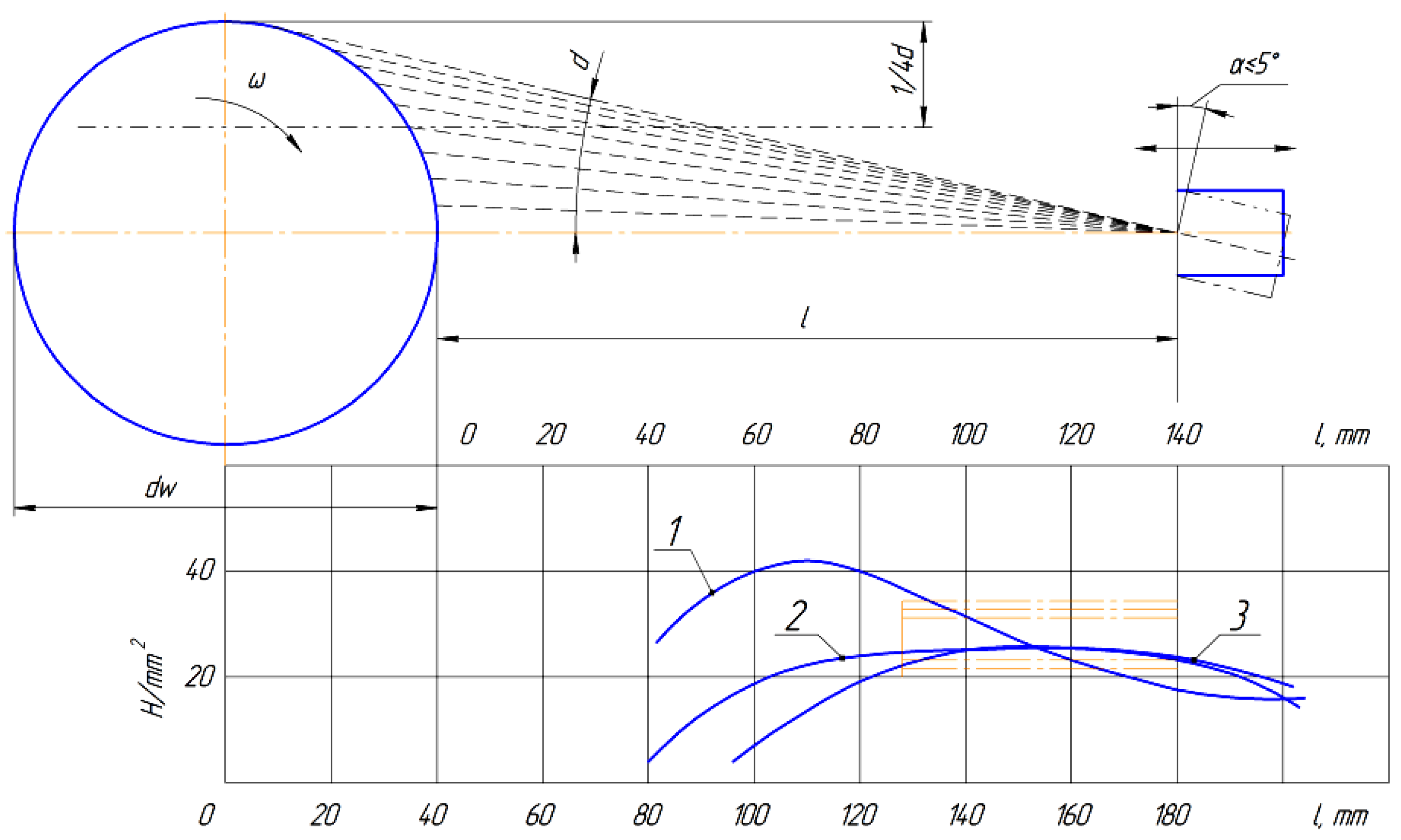
The main reason for cracking when spraying with the PN 35T75 powders was overheating. With repeated spraying, the surface of the substrate overheated and unevenly expanded with the base of the part, microcracks reappeared, and adhesion (adhesion strength) decreased. It was experimentally established that the cracking and adhesion of the coating are affected by the spraying mode (
J is the current strength (A),
U is the voltage, and
V and
l are the spraying distances (mm)). According to the results of the production experiment with the Remplasma LLP restoration technology, the dependence of the adhesion strength and the level of cracking of the coating on the spraying distance were established as y = −0.0667x
2 + 0.9018x + 1.7667 (
Figure 3).
It follows from the graph that the optimal option was Uw at 180–190, a dr of ≥140 PNC3P3, a Jw of 180–200, and a % Gr of >15%.
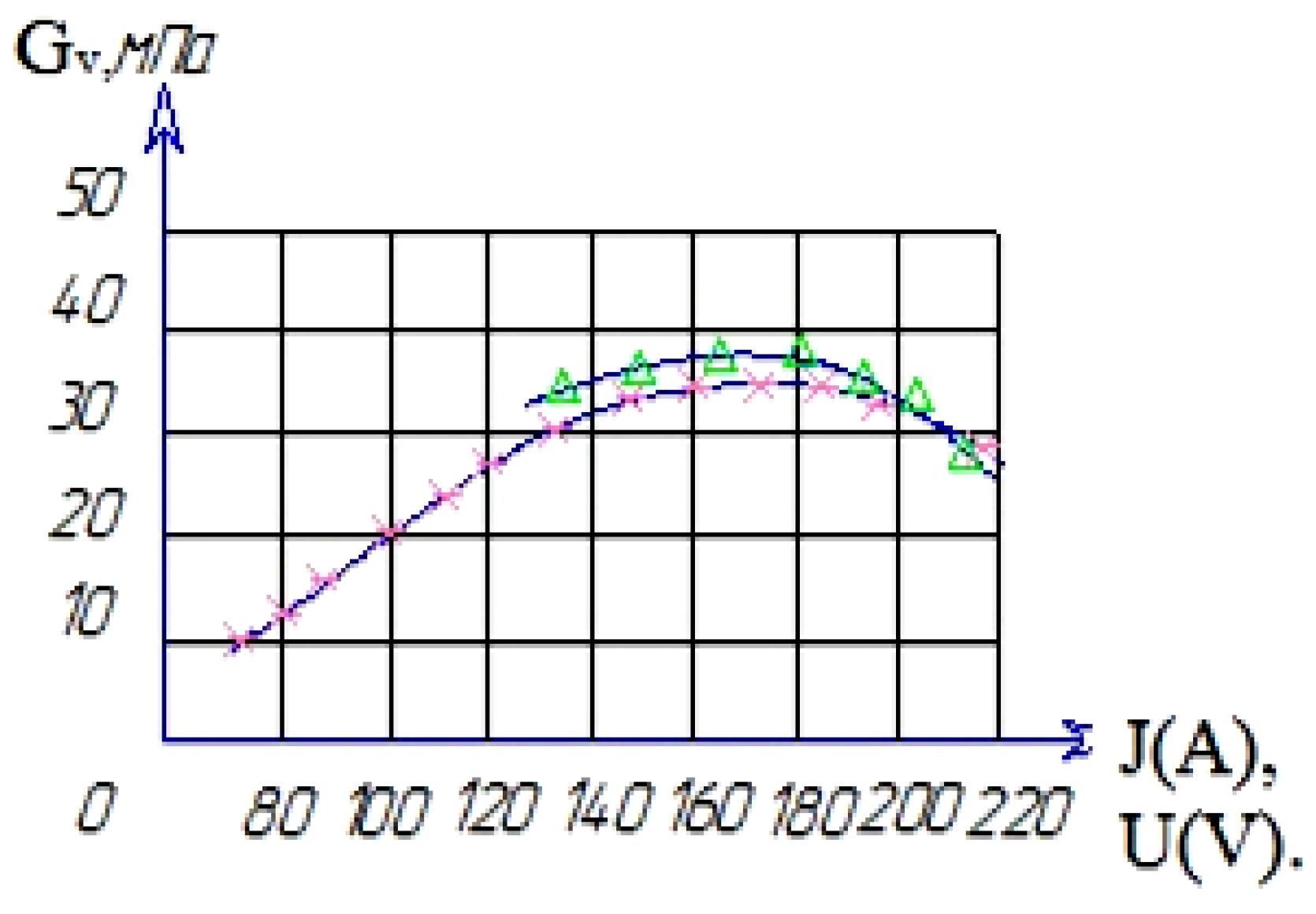
When spraying parts, especially with sprays that significantly exceed the diameter of the sprayed surface, it is necessary to strive for a minimum thickness of spraying and the equality of the uneven expansion coefficients of the sprayed and base metals. This makes it possible to reduce the deformation of the part and the zone of thermal influence, as well as to reduce the likelihood of cracks in the sprayed metal (
Figure 4). During the spraying process, there is no significant increase in the base temperature, so the particles cooling after impact are compressed more than the metal bases. As a result at normal temperatures, residual compression or tensile stresses occur in the sprayed coating.
When spraying coatings on a base of small thickness, residual stresses arising in the coating can lead to its deformation. In cases where the substrate has great rigidity and the coating is thick enough, residual stresses can lead to the formation of cracks in the sprayed metal or its separation from the substrate.
It is believed that residual stresses also affect the mechanical and chemical characteristics of the coating. However, the nature of this influence has not been fully studied. Measurements of average residual stresses in coatings of various thicknesses were carried out on samples of 1.5 mm × 10 mm made of low-carbon steel, on which coatings of molybdenum, nickel alloy, and aluminium oxide were sprayed. For measurements, a method was used to determine the magnitude of residual stresses via the curvature of a rectangular sample. In molybdenum coatings of small thickness, residual tensile stresses occurred. With an increase in the coating thickness, the residual stresses decreased, and at a coating thickness of 0.35–0.4, the residual stresses became zero. With a further increase in thickness, residual compression stresses appeared in the coating; these gradually increased with increasing coating thickness. When the coefficient of thermal expansion of the sprayed material was equal to or greater than the thermal expansion coefficient of the base material, residual tensile stresses occurred in the coating. In other cases, residual compression stresses occurred in the coating. Currently, the causes of residual stresses in coatings have not been fully identified.
The next task was to build a mathematical model based on the results of the experiment. Generally in experimental studies, the analytical dependencies between variables—formulas and coefficients of these formulas—must be determined. The developed multivariate regression model could also be used to determine the optimal level of the studied indicator via mathematical programming methods.
We first consider the methodology for solving the problem in this formulation through the example of determining the maximum level of fatigue strength by the factors under consideration. The regression equation obtained by us with the program Lindra, use to determine the relationship between hardness and its forming factors, comprises Formulas (6), (7), and (8):
Similarly, the factors that form tension are:
In the same way, the factors that form adhesion are:
Next, the problem was solved on a computer using the program Excel and the “solution search” method.
Thus, experimental studies were carried out using the method of the planning a multifactorial experiment. Formally, the purpose of the experiment was to determine the numerical values of the coefficients of regression equations. To determine the optimal conditions for the processes, we found the values of the x1, x2, … xk factors, corresponding to the extrema of goal functions or target functions (6), (7), and (8). The obtained mathematical models in the form of regression equations allowed us to determine the optimal deposition modes and the effective limits of their variation.
It was experimentally established that the cracking and adhesion of the coating are affected by the spraying mode and the design of the plasma torch. The listed modes (J—current strength: −180–200 A; U—voltage: −180–190 V; l—spraying distance: −120 mm; plasma jet velocity: −280 m/s; multi-component structure: turbulence) could be considered optimal since they provided a high linear particle energy, a high mixing coefficient (turbulence), and the introduction of particles to a depth of up to 0.3–0.5 mm.
4. Metallographic Studies of the Physico-Mechanical Properties of the Structure of the Recovered Sample
The next stage of the experiment was to conduct an independent metallographic examination based on the Institute of Physics and Technology of the National Academy of Sciences of Belarus. Three samples were prepared in the laboratories of the Institute. In the process of image preparation, a SECOTOM-50 precision cutting machine with a movable cutting table of variable speed, a CitoPress-15 programmable single-cylinder mounting press, and a Tegramin-30 machine for grinding and polishing samples were used.
The abrasive treatment of the grinds was carried out in several stages, constantly reducing the particle size of the abrasive discs. Several types of discs (MD-Piano and MD-Allegro) were used in the processing process in combination with the recommended type of suspension (water and diamond suspension of 9 microns each). The remains of the abrasive from the slot were removed using ultrasonic cleaning. After grinding, the slot was washed with water and polished (for diamond polishing, an MD-Dur disc and a diamond suspension of 6 microns were used; for oxide polishing, an MD-Nap disc and an OP-U suspension were used) until a mirror gloss (Ra 0.1) was created with the same Tegramin-30 machine.
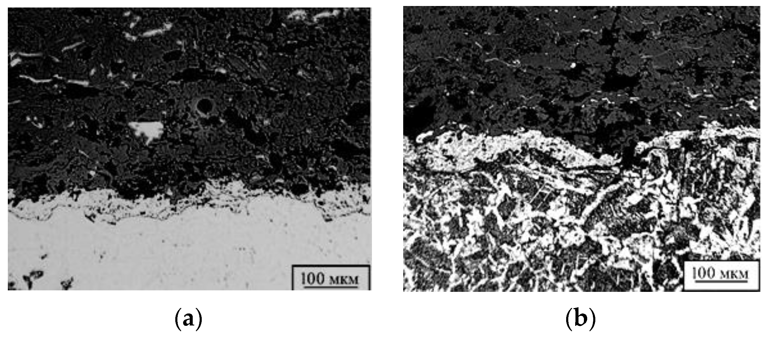
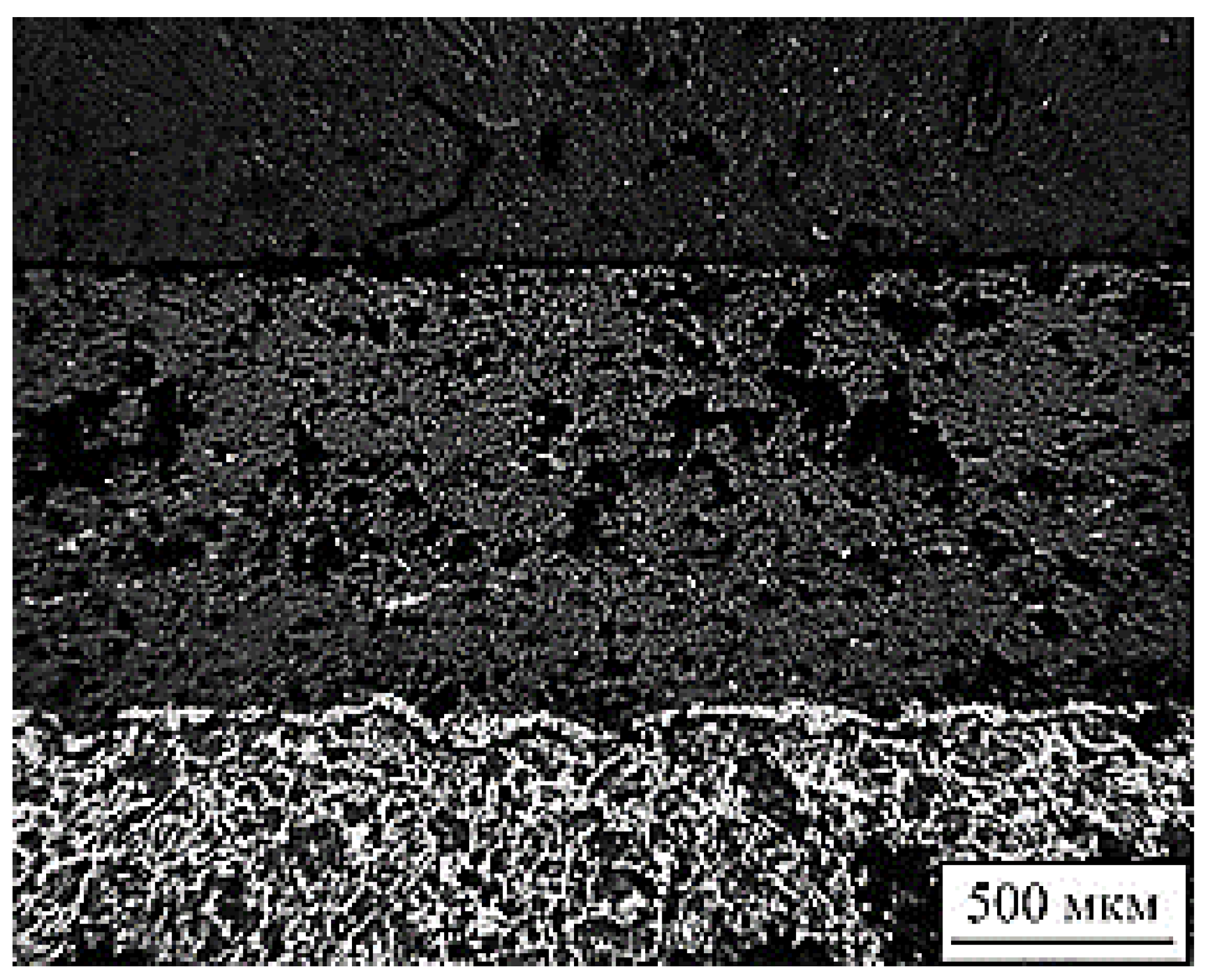
To conduct the study, some of the samples were etched. Furthermore, samples from both groups were measured on a light microscope at magnifications of 50×, 100×, 250×, and 500×. Photos of microstructures are shown in
Figure 5.
Sample “1”: As a result of visual inspection, a large number of pores and additional inclusions were noted in the structure of the sprayed material. The thickness of the sprayed layer was 2–3 mm. The microstructure of the deposited metal consisted of medium-needle martensite and doped ferrite, separated along the boundaries of the primary austenitic grains during the crystallization of the deposition (
Figure 5).
At a distance of 1.0–1.5 mm from the fusion boundary, the structure of the base metal consisted of perlite and ferrite. The microhardness of the individual structural components of the sprayed metal was in the range of 1300–1500 HV. The microhardness of the base metal decreased from the fusion boundary deep into the sample from 1500 to 250 HV (granular perlite and ferrite metal base).
Conclusion: the porous structure indicated some overheating of the metal during spraying and the low thermal conductivity of oxides, which made it difficult to warm up the sprayed particles. It was necessary to change the basic parameters of spraying in order to reduce the running energy or to change the composition of the substrate powder.
Sample “2”: As a result of visual inspection, the presence of pores and additional inclusions were noted. The thickness of the deposited layer was 1.8–2.0 mm. The microstructure of the deposited metal comprised medium-needle martensite and alloyed ferrite, and the near-seam zone of the base metal comprised eutectic ledeburite. Cementite inclusions larger than in sample “1” were found at a distance of 0.5–0.7 mm.
Conclusion: the rough needle structure of the deposited metal and the value of the actual grain at the levels of 4–5 points of GOST 5639-82 indicated some overheating of the metal during the surfacing process. It was necessary to change the basic parameters of the surfacing in order to reduce the running energy and thermodynamic effects.
Sample “3”: As a result of visual inspection, the porosity of the sprayed metal was observed. The thickness of the sprayed layer was 1.8–2.5 mm. The microstructure of the deposited metal comprised fine-grained perlite and a little ferrite.
The microhardness of the deposited metal was 1300–1460 HV, closer to the fusion boundary, and the microhardness increased slightly and reached 1470–1550 HV. A distinctive feature of the deposited metal of this sample was the presence of so-called “unreacted” particles, which means that the linear energy in the deposition process was insufficient for their penetration.
Conclusion: the absence of ferritic formations, the presence of “unreacted” particles in the deposited metal, the insufficient diffusion of carbon from the base metal indicated an insufficient amount of linear energy during surfacing.
Microhardness measurements were carried with on a microhardness meter with a load according to GOST 9450-76 standard: we conducted the “measurement of microhardness by indentation of diamond tips” from the base of the sample surface to the edge of the coating surface to the base with the capture of the transition zone (
Figure 6).
In analysing the results of studies of the microhardness of the sprayed and base metal of the tested samples (
Figure 5), thermal influence was found that in the near-shock zone of sample “2”. The microhardness of the individual structural components of the sprayed metal was in the range of 1200–1450 HV. The microhardness of the base metal decreased from the fusion boundary deep into the sample from 1450 to 300 HV (perlite).
Variations in the magnitude of microhardness from near the suture zone to the base of the material indicate local thermodynamic effects. This process has a positive effect on the uniformity of the coefficient of thermal expansion of the material (compression and stretching). The establishment of optimal values of the coefficient of thermal expansion allows one to control and minimize the concentration of internal stresses in the structure of a material. The established dependence (y = 3.4697x2 − 134.37x + 1533.7) of the change in microhardness (y; in HV) on the penetration depth (x; in h) of the material made it possible to reasonably choose technological and temperature regimes for obtaining coatings with specified physical and mechanical properties.
Based on the analysis of the results of the study of the physical and mechanical properties of the restored surfaces by laser energy sources, the following conclusions were made:
- -
The hardness of the coating and the microhardness of the substrate, as well as the wear resistance of the surface, were significantly affected by the grain size and the phase structure of the material, which was improved by laser modification and depended on the modes of the technological recovery process (spraying distance, voltage, and ratio of 21% propane transporting gas), when the composition of the material was 15Cr17Ni12V3F.
- -
The absence of ferritic formations and the insufficient diffusion of carbon from the base metal indicated an insufficient amount of linear energy during spraying. Values of the actual grain at levels of 4–5 points of GOST 5639-82 indicated the overheating of the metal during spraying.
- -
Medium-needle martensite and cementite provided high linear energy during spraying, and the microhardness of the sprayed metal was 1300–1500 HV.
5. Investigation of Stresses in a Railway Wheelset Restored by a Coating 15Cr17Ni12V3F
Eric E. Magel, Yan Liu, Braghin F., Bruni S., Lewis R., Wang Wenjian, Guo Jun, and Liu Qiyue [
28,
29,
30] made significant contributions to the study of coatings for the laser hardening of car wheels. Analysing their research revealed that laser surfacing allows for hardening directly under a car without rolling out the wheelset and obtaining deposited metal with increased physical and mechanical characteristics.
Previously, vibro-arc surfacing was used in the restoration of car wheels. A laser recovery method, which consists of surfacing a layer (coating) on the rolling surface of the car wheel via the minimal melting (sub-melting) of the base and filler material (powder) with good physical and mechanical properties (controlled chemical composition of the deposited layer), was proposed [
31,
32].
The parameters and modes of laser deposition: 15Ni17N12V3F powder was used as an additive material (this type of additive powder has a hardness of HRC 40, and nickel-based refractory powders are corrosion-resistant, heat-resistant, thermal-resistant, have a low melting point (960–1000 °C) that helps to reduce the thermal effect on the wheel and significantly reduce the level of residual deformations and stresses in the base metal) with a radiation power of 3.2–3.5 kW, a surfacing speed of 64–72 m/h, a radiation focusing-spot diameter of 2.5–3.0 mm, and a mass consumption of surfacing powder of 0.25 g/s.
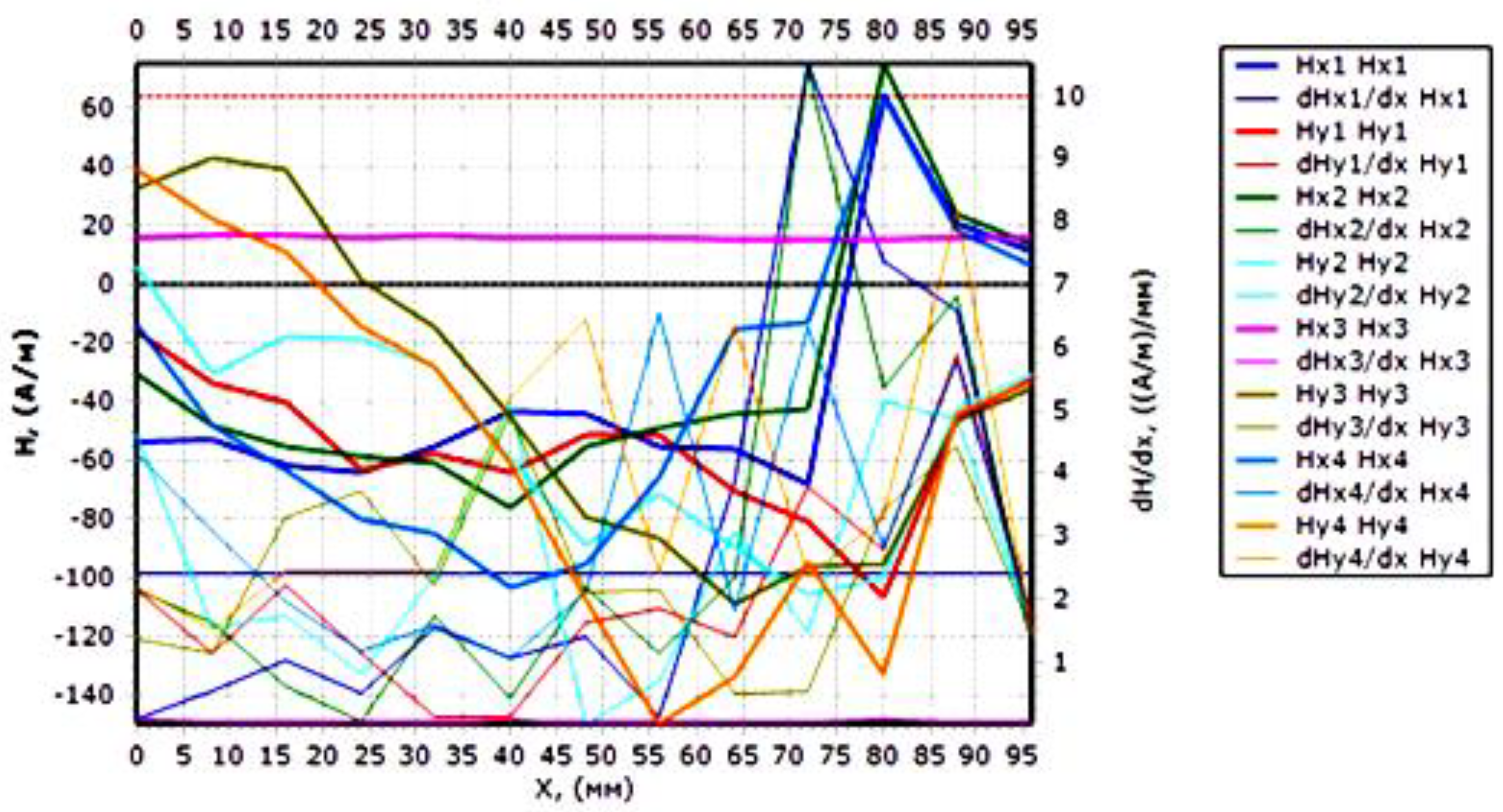
According to the test results, it was found that the zone of origin and development of the defect coincided with the plane of the design section. At the same time, the concentration of internal stresses at the point of the dangerous cross-section increased. During the subsequent loading of the wheel, the concentration of internal stresses in the metal increased, which was accompanied by a change in the structural component. The results of the study of the concentration of internal stresses are presented in the form of a graph (
Figure 7).
The control and measurements were carried out on the length of the working surface of the wheel in places most susceptible to mechanical and dynamic wear. Scanning with a sixteen-channel sensor of the IKN-7M-16 device was carried out from the root section of the wheel to the peripheral one or, conversely, along three coordinate axes.
The solid red line on the graph (
Figure 7) shows the change in the magnetic field per meter of the sample length (A/m), on which no clear bursts are visible. The red dotted line shows the permissible voltage value for this type of product. The blue solid line of the graph (gradient) shows the places of the surge in the magnetic field intensity, which characterizes the formation of stress concentrations on each millimetre of the sample (A/mm). A change in the sign indicates the direction of compressive or tensile stresses.
According to the results of the control, the sections of the wheel operating in the most stressful conditions were determined. Such sections were those in which the stress and strain concentration lines (line Hx) were located transversely and had the maximum stress intensity coefficients. The values of this coefficient were automatically determined and were displayed on the screen when the operator calls.
The stress concentration zones were located at the places where the sample defects occurred at a control diameter from 71 to 82 mm and 10 mm from the critical point; see
Figure 6. If the bending moment and the acting stresses were most important in the dangerous section with the selected pinching scheme, then these values were less by about 20%–25% when bending other types.
The values of residual stresses in the recovery zone did not exceed the threshold values. The structure of the metal in this case was sorbitol, oriented to martensite. The hardness ranged from 26 to 30 NRS. Therefore, the need to establish the dependence of changes in internal fatigue stresses on the structural-phase state of the metal preceding the appearance of microcracks and the complete destruction of the wheels of a railway car was justified.
Based on the results of the study of fatigue stresses in the metal structure of the wheel, the authors (for the first time) formed a database that allowed us to interpret the scattering of magnetic flux in weak magnetic fields per unit area depending on the phase structure of the metal and the features of the technology of their recovery. The results of the study of the causes of the stress state of the metal structure made it possible to form a database on the correspondence of the structural and phase composition of the magnetic field strength and the defect (
Table 3).
Each type of defect was found to correspond to a certain structural-phase component and level of magnetic field strength. For example, with fine-grained perlite and ferritic inclusions, the boundary of primary austenitic grains was very poorly traced (sample No. 4), which led to microcracks and ensured the high porosity of the material. The established causal relationship between the defect and the magnetic field strength characterized the inefficient parameters of the recovery modes, which resulted in the weak diffusion of carbon from the base metal and an insufficient amount of linear energy during plasma sputtering.
Considering sample No. 1, it can be noted that the surge in the magnetic field strength according to the measurement results was Nh = 62 A/m. This corresponded to the structural-phase state of the sorbitol oriented to martensite and was characterized by the absence of technological defects. However, under the severe operating conditions of a railway train, dynamic and vibration loads increase, at which fatigue processes develop in the wheel and lead to deformation and destruction.
Thus, the change in the life of a wheelset is largely determined by the structural and phase components, and the degree of failure time in most cases depends on the origin of fatigue cracks, the primary cause of which is the concentration of internal stresses. Therefore, the need for the revision of recovery methods and methods for the diagnostics and forecasting of resource has been proven. The main indicator of the resource should not be the number of working cycles (NNE) until the complete destruction of the blade, as prescribed in classical methods and reference books [
33]; instead, it should be the number of cycles until the appearance of maximum internal stresses NNH, preceding the formation of microcracks. In turn, the presented step-by-step integrated forecasting method should be completed by calculating the crack resistance coefficient while considering the coercive force.
6. Change in Dynamic Load at the Moment of Deviation of the Worn Wheel Contact Spot from the Design Axis of Movement
When studying the principles of dynamic load redistribution and changes in the deviation of the wheelset surface contact spot from the design axis of movement, it is necessary to:
Determine the forces acting on it.
Determine the stresses that occur in its elements.
Evaluate the strength and durability of the structure under consideration.
Justify the permissible limits of the area of deviation of the wheel profile contact spot from the design axis of movement.
The wheelset is affected by almost all loads acting on the car [
34,
35,
36]. We determined the main forces that most significantly affect wheelset durability, and these were taken into account in the calculation of the axis (9).
The vertical static load
Pst of a loaded car (gross), which falls on the axle neck, was calculated with Formula (9):
where
mgr is the car gross weight,
mo is the number of wheel pairs in the car, mws is the wheelset weight,
mn is cantilever weight of the axis (from the end of the axis to the wheel tread plane),
g is the acceleration of gravity, and
is the average value of the utilization capacity of the car (passenger cars
= 1). Therefore, according to Formula (9), neck load includes part of the wheelset axle weight and the incomplete carrying load of cars in operation must be considered.
The vertical dynamic load caused by the vibrations of the sprung wheels was determined with Formula (10)
where
kd is the coefficient of vertical dynamics.
Based on the statistical processing and theoretical analysis of experimental data, while considering the probability of repetition of dynamic loads, we recommend the following Formula (11):
where
λv = 1.0 is a value depending on the number of wheelsets of the bogie;
A = 8.125 is a value depending on the flexibility of the car suspension;
B = 5.94 × 10
4 is a value depending on the car type, s;
υ = 15–33 is the car speed, m/s; and
fst = 0.0463 is a static camber for suspension, m.
The main drawback of the classical methods of power calculation is the need for calculation under ideal conditions, where the calculated research object meets the standards of the manufacturer. In real operating conditions, the tread surfaces of wheelsets intensively wear out [
37,
38,
39]. Wear causes the degradation of the tread surface in its structural parameters (fatigue wear) and changes in the spatial shape, design geometry, and surface roughness
. For example, the vertical static load
Pst on the wheel changes as a result of the wear of the tread surface and the wheel flange. Changes in the utilization factor of the load capacity of the car
affect the amplitude of cyclic forces during operation. As a result, the useful traction forces acting at a certain negative angle to the wear area form the moments of resistance forces. Thus, it is necessary to solve the scientific problem of establishing a dependency of static loads
Pst on the utilization capacity of car
and the gross weight of the car
mgr. It is also necessary to integrate classical calculations to real operating conditions by considering dynamically unstable loads. This problem was solved by establishing dependencies of dynamic load
Pd on the static load of the car
Pst and of vertical dynamic coefficient
kd on the velocity υ of the car. The regression equation of the studied dependencies is shown in
Table 4.
Considering the asymmetry of the oscillations, the vertical dynamic load was considered to be applied to one neck, and on the other, it was assumed to be equal to zero.
The vertical load from the centrifugal force, loading one neck and unloading the other (12), is as follows:
where
Nc is the centrifugal force of the car per wheelset,
hc is the height of the centre of mass of the car from the axis of the wheelset, and 2
b2 is the distance between the midpoints of the axis necks.
The vertical load from the wind pressure on the side surface of the car, loading one axis neck and unloading the other, can be calculated with Formula (13):
where
Hw is the wind pressure acting on the car and
hw is the distance from the resultant wind pressure to the wheelset axis.
Due to the slow change in time of the centrifugal force and wind pressure, the probability of their repetition was assumed to be equal to one, and they were considered in the same way as the static load. Total vertical load can be calculated on the left neck as follows (14):
It can be calculated on the right neck as follows (15):
Thus, the most difficult loading conditions were observed on rim 1 (
Figure 2a), especially on its tread surface. It was calculated that when moving along curves, as well as on straight sections of the track, wheel sliding could be observed, which leads to shock load and, consequently, the chipping of places affected by contact fatigue cracks and the formation of cavities on the tread surface [
40,
41,
42]. This phenomenon occurs due to the tortuous movement of the wheelset or differences in the diameters of the wheels pressed on one axis.
7. Discussion of the Results of Fatigue Stress Distribution Simulation for Worn Wheel Contact Elements
The next problem of the research was to assess the adequacy of the calculations and to set the limits of internal wheel stresses that occur on the tread surface of a wheel under the action of cyclical dynamic loads. The problem was solved using the simulation of loading processes and stress formation in the critical elements of the wheel.
The simulation of interaction between a wheel and a rail is a complex system problem because this system is hierarchical and has a wide range of properties that dynamically change over time [
43,
44,
45].
A professional package for static analysis of structures, GearTrax, was actively used during the research in addition to the main program of SOLIDWORKS (Vizualize 2020). The choice of the GearTrax package was justified by its configuration, which included an interactive graphical simulation tool with advanced three-dimensional graphics, a combined load analysis tool, a gap element analysis tool, a tow transport inertial load analysis tool, and others.
As is well known, the life cycle of any pair of engagement and coupling includes the stages of natural run-in, steady wear (useful life), and progressive wear (time of major repairs). The size of the gap that occurs during the wear of the tread surfaces has a negative impact in the form of an increase in dynamic forces and shock loads. These processes are difficult to predict in experiments, especially with a short study time. Therefore, we assumed that the wheel axle box, the axle, the frame of the car bogie, and the spring beam were technically serviceable and had passed full maintenance.
The analysis was carried out using the Static II Pro package. Given the nature of the simulated experiment, which investigated the resulting stress in the contact surfaces, the criteria for quality at the geometric indicators were the following indicators: ratio of the minimum bias, Xmin; condition that X > Xmin; radius of curvature at the critical point of the profile Rol; absence of interference Rol < Rop; no-undercut condition Rol > 0; and an overlap factor. Based on the calculation results, a report was displayed on the monitor [
46].
To determine the volumetric stress–strain state of an all-rolled wheel, we used the SolidWorks software package based on the finite element method and evaluated its stress strength. Modelling took place in three stages:
Stage I. The preparation of the initial data for the operation of the pre-processor consisted of the development of a geometric model of the wheel, the creation of a volumetric finite element model of the wheel, and the calculation of the loads acting on the wheel and their models.
Stage II. The task of the solver was to determine the stress–strain state of the wheel.
Stage III. The work of the postprocessor was the output of the results of the analysis of the stress–strain state of the wheel and the evaluation of the strength of the wheel model following stresses.
The properties of the material were considered both mechanical and physical in accordance with the grade steel 2 for the manufacturing of railway wheels.
During the modelling, the following input data were entered into the database: yield strength of steel, hardness, deformation coefficient, contact strength Poisson’s ratio of μ = 0.25, Yung’s modulus of E = 20 × 1010 H/m2, and durability coefficient. The basic data for the calculation of steel were taken from the electronic library of the SOLIDWORKS program.
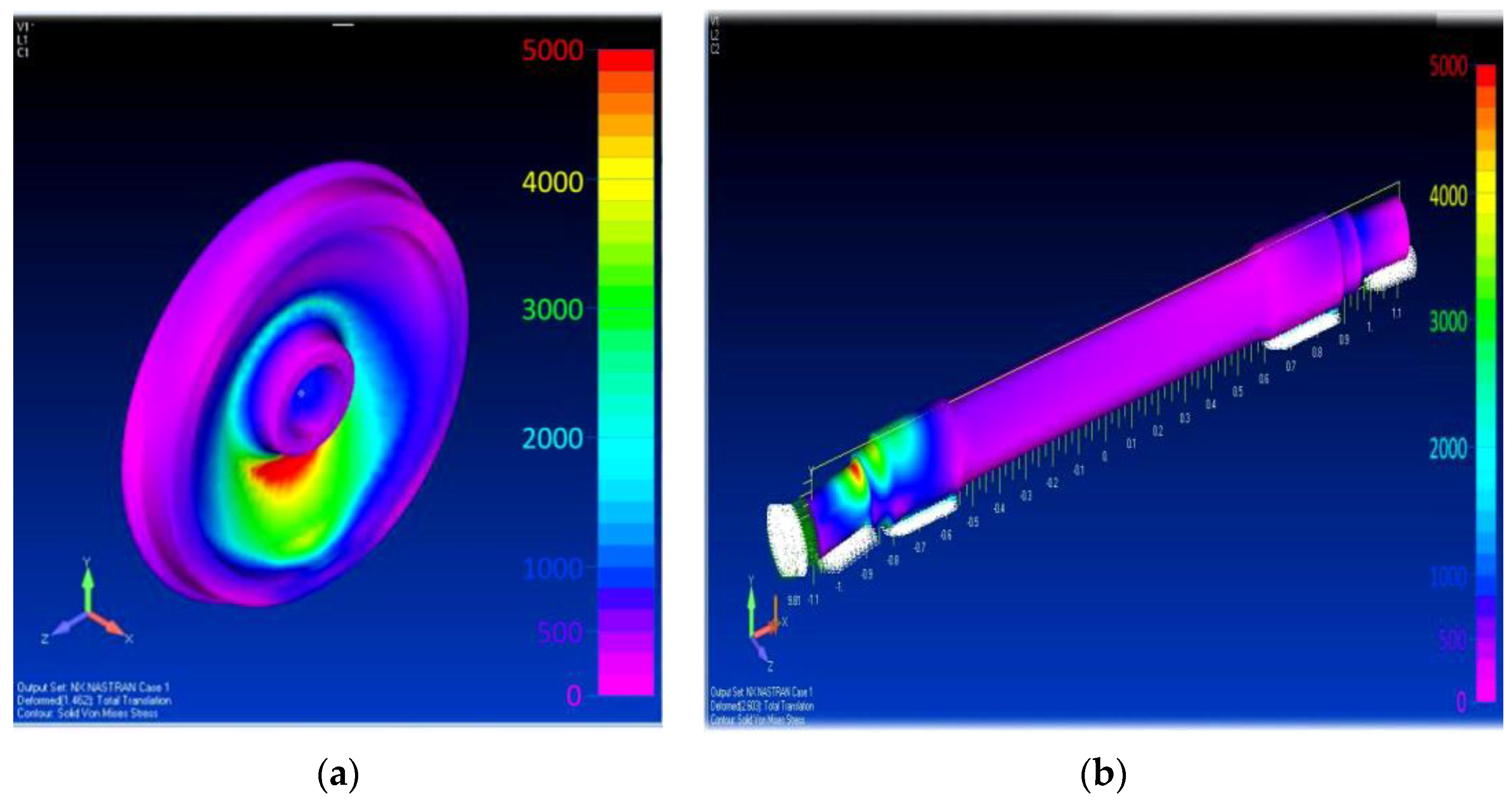
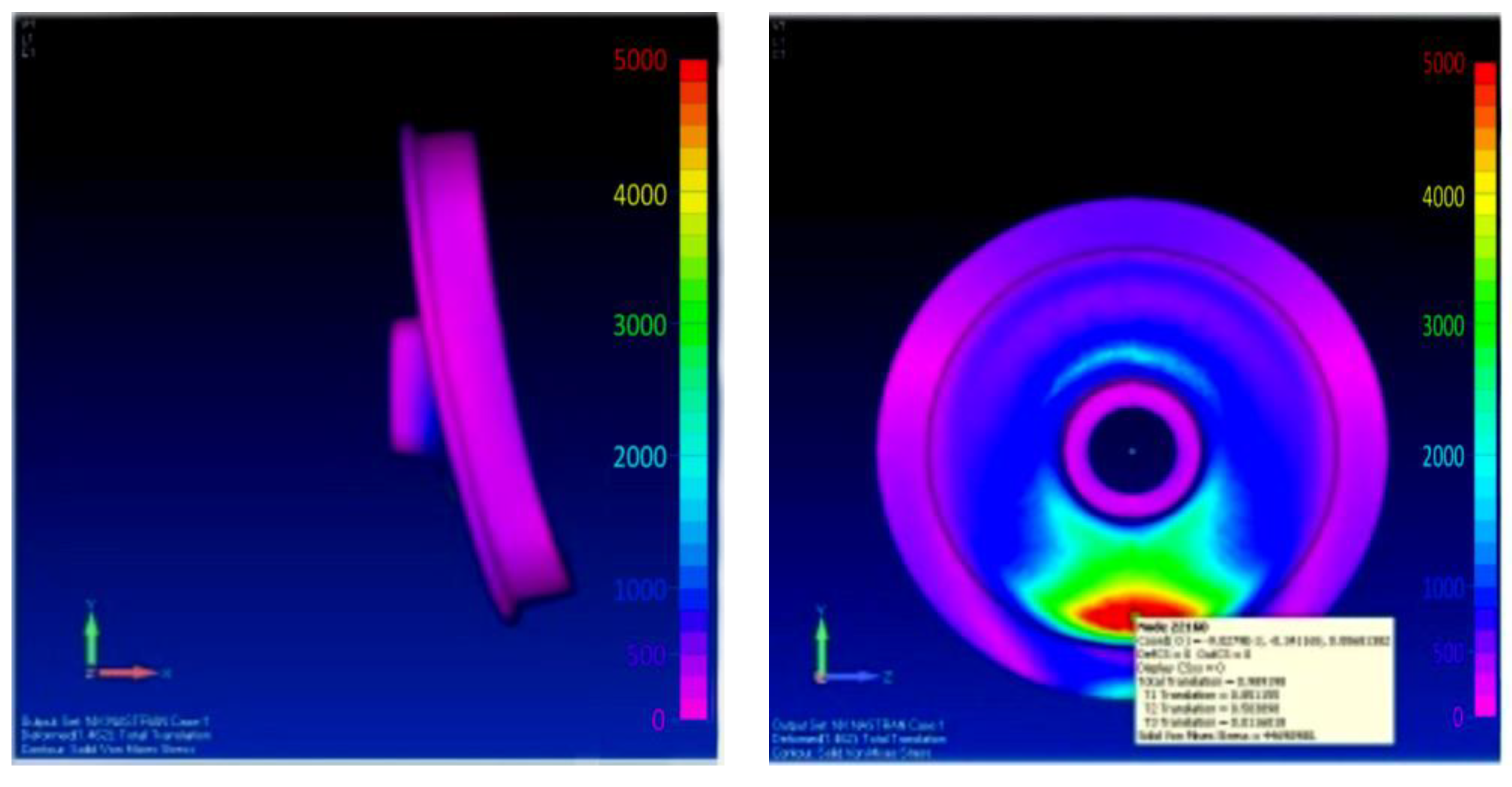
In the SOLIDWORKS interface, we set the coordinate axes along which the action of forces and moments was directed at a given load in the contact area (
Figure 8). In addition to quantitative characteristics, we defined qualitative indicators. Then, we set the applied load in the contact spot at the base of the flange depression to its dividing diameter. The colour spectrum indicates the places that were subject to the greatest load [
47].
The source area of contact stress and bending on the wheel disk was small, but the depth distribution of spectral and colour diagrams shows that the tread surface of the wheel and the disk at the base of the centre shaft operated under high alternating loads that especially occurred over a short period. The concentration of critical stresses had a local character and was short in time. The colour scheme characterizes the contact section of the wheel operating with stresses σF = 85.347 × 10²–123.025 × 10² MPa. This load mode proceeded within the permissible limits under the condition of strength σF ≤ [σF].
When moving a car, the torque from the traction gearbox is transmitted through the axle to the wheel of the railway car. Hence, the action of the drag forces and the inertia forces of the natural masses primarily affect the tread surface of the wheel. Here, the acceleration (ε
wh) and angular velocity (ω) of the wheel rotation during its movement reached their maximum values during acceleration, braking, and on the radius turns of the car. In the period
t1 (acceleration time when the car was moving), the initial stage of the interaction of the contact pair occurred and the internal stresses
σF and
σH sharply increased. This period corresponded to the contact of the wheel surfaces and the ridge with the rail at a given force of 48,333 kN with stresses of
σF = 68.347–1123.025 MPa. The value of the load reached its maximum during the final period of turning the car at radii
t3. During braking, forces and moments of inertia are added to the torque, exerting pressure on the contact area of the worn surface. The pressure value progressively increases [
48,
49,
50]. Here, we found maximum stress values that tended to disrupt the power balance and deform the tread surface and wheel flange (
Figure 9).
The first force disturbances were transmitted to the axle at the base of the wheel. This is also evidenced by the red colour of the spectrum (
Figure 8b).
After that, the stresses were transmitted to the working surface of the wheel. When the maximum stress values were reached, there was a structural violation of the metal and, as a result, fatigue deformation, chipping, and fracture. When the load was unevenly distributed over the contact spot caused by fatigue stresses σN increasing over a short period, the destruction area of the contact surface increased along the wheel braking path.
The path travelled by the wheel at the moment of braking was accompanied by a slow rolling, i.e., by a decrease in the contact area with increasing stress and multidirectional vectors of moments of inertia along the x-axis. This moment was critical because it violated the condition of equilibrium in the force balance, current contact stress, and bending inside a “cavity” of wear.
The studied processes explain the nature of destruction and stressing in the contact zone on the tread surface of the wheel [
51,
52,
53,
54]. As a rule, destruction occurs in a metal structure in the same stress zone, corresponding to the maximum range of moments of forces at the time of braking and turning of the railway car.
Therefore, when designing or developing wheel recovery technology, the metal of rim 1 must have great general strength, high impact strength, and wear resistance. The metal of wheel nave (held on the axis by elastic forces) must have the necessary viscosity, and the metal of disk must have the necessary elasticity.
Many car wheels are only tyred, using harder materials with subsequent heat treatment separately from the centre to the profile. When it they are extremely worn out, they are replaced without changing the wheel centre. Such wheels are now common in several Western European countries. However, they have significant disadvantages such as lower strength and operational reliability, higher costs for the formation of wheelsets, and greater weight (by 36 kg for wheels with a diameter of 950 mm). Therefore, tyred wheels are being replaced by steel, tyreless all-rolled wheels [
55].
When choosing and developing an effective method for restoring car wheels using thermomechanical action, it is necessary to comply with the requirements for changing and modifying the mechanical properties of the treated wheels [
56,
57]. The physical and mechanical properties of the restored wheels must comply with the following standards and be subjected to the universal forecasting methods: ultimate resistance:
σu = 880–1080 MPa; relative elongation δ of no less than 10%; relative narrowing ψ of no less than 16%; Brinell hardness of no less than
HB = 2430 MPa; and impact strength KCU (KCV) at a temperature
T = 293 K (+20 °C) of no less than 0.2 MJ/m
2.
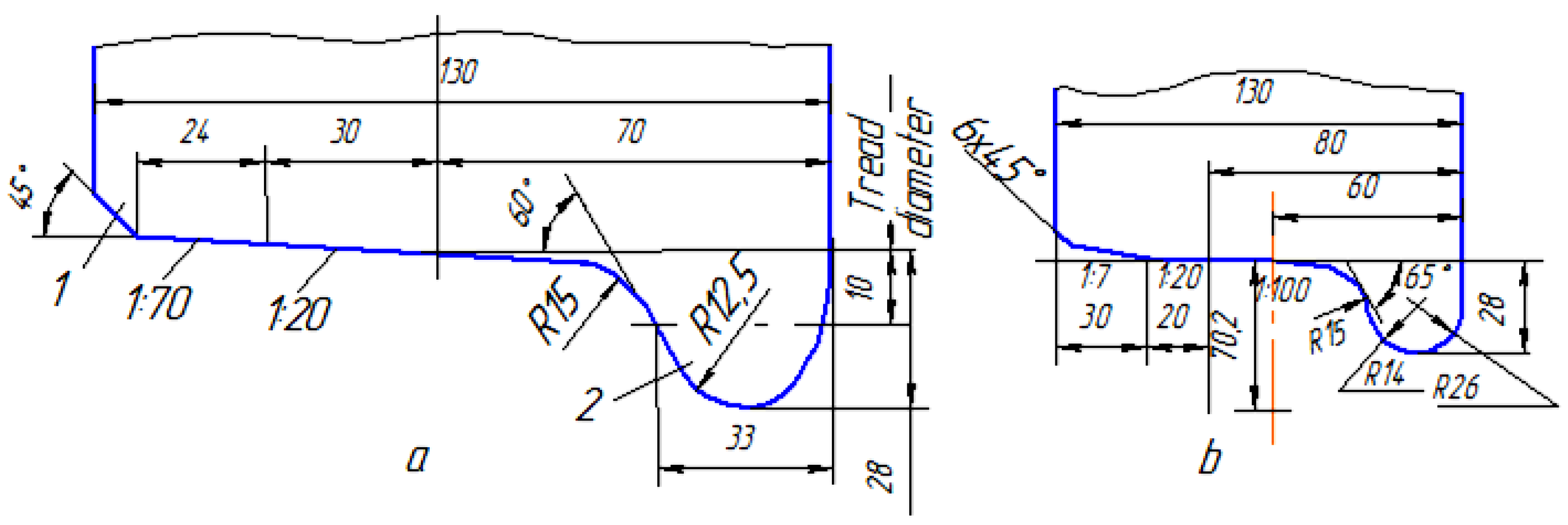
Studies have established that the shape and profile of the wheel tread surface are important for the rational interaction of the wheel and rail track (
Figure 10a). Wheel spatial dimensions and design geometry affect the formation of shock loads and internal stresses that lead to fatigue processes preceding the development of microcracks.
On the inner side of the rim, we found a 2U flange that protected the wheelset from the derailment. The flange height was
h = 28 mm, and the thickness, measured at a distance of 18 mm from its top, was 33 mm [
58,
59]. The flange deflection angle (α) was 60°. The conical tread surface had inclines of 1:20 and 1:7 and a bevel of 1 (
Figure 10a). This shape of the wheel tread surface ensured the free movement of cars along the curved sections of the track, centred the wheelsets on straight sections, and provided more uniform wear of the tread surface of wheels. However, the conical shape of the tread surface caused a sinuous movement of the wheelset and, consequently, the car as a whole.
A taper of 1:7 and a bevel raised the outer face of the wheel above the top of the rail during the run-out, ensuring the crossing of switches in the presence of rolled metal or an influx of metal on the tread surface of wheels.
The tread line was located at a distance of 70 mm from the inner face of the wheel, and the distance between the tread lines of one wheelset was found to be 1580 mm.
The All-Union Research Institute of Railway Transport has proposed a new profile for a car wheel tread (
Figure 8b). Preliminary experiments have shown that wheels with such a profile have 1.5–2 times less flange wear. The angle of inclination of the outer edge of the flanged increased to α = 65°, thus improving the stability of the wheelsets on the rails and the safety of the car movement.
A similar car wheel tread profile is being introduced in a number of European countries. In this case, the angle of inclination of the outer edge of the flange is increased to 70°. According to research by the International Union of Railways, the use of a new profile reduces wheel wear by 30%, diminishes the likelihood of derailment, and improves the smooth running of a car.
8. Determination of the Dependence of Changes in Normal Contact Stresses on the Design Deviation of the Wheel Wear Contact Area
Research institutes, car-building plants, and metallurgical plants recommend the manufacture of wheel structures made of low-alloy steels with increased resistance to the formation of fatigue, the formation of thermal cracks, and increased wear resistance [
60,
61].
However, these developments have not considered changes in the design geometry, shape, and mechanical properties of the wheel during the car operation. Multidirectional vector forces and moments of inertia at different speed modes and load capacities of cars lead to the accelerated degradation of the tread surface of the wheel [
62,
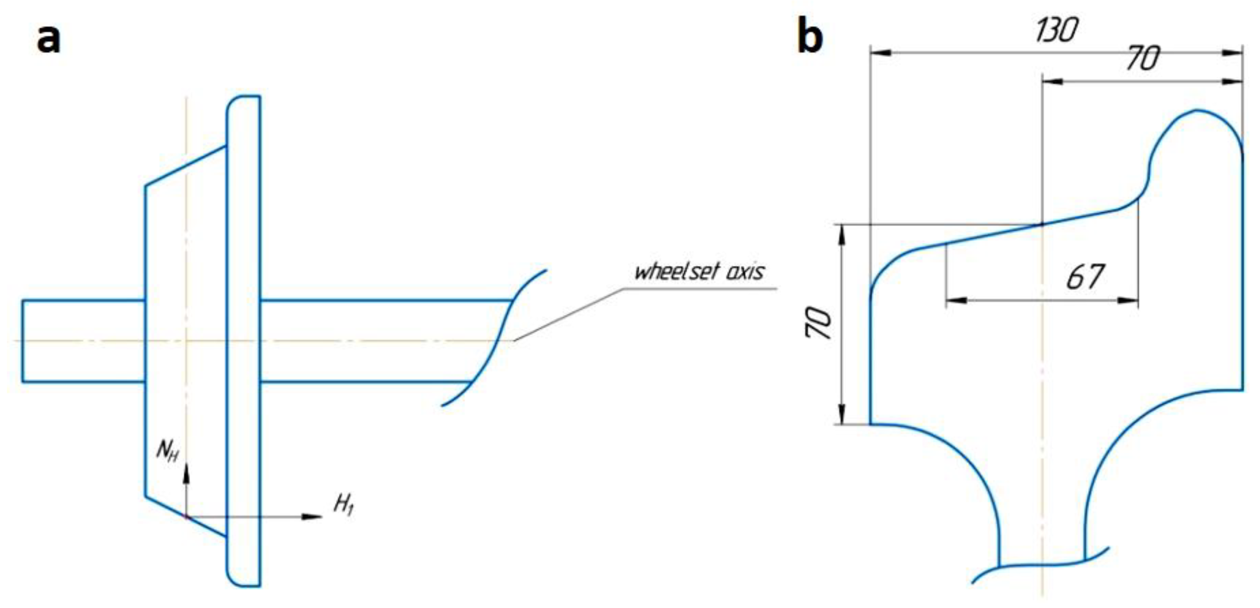
63]. To understand the physical meaning of the formation of defects on the contact surface of the wheel and rail, it is necessary to solve the scientific problem of determining the dependence of the influence of the wear value on the formation of bending stresses in the wheel. It is important to note that wheel wear (such as tear-outs, bumps, and scratches) are probabilistic and are very difficult to simulate. Therefore, a simplified cross-section design of the wheel under study was considered (
Figure 11).
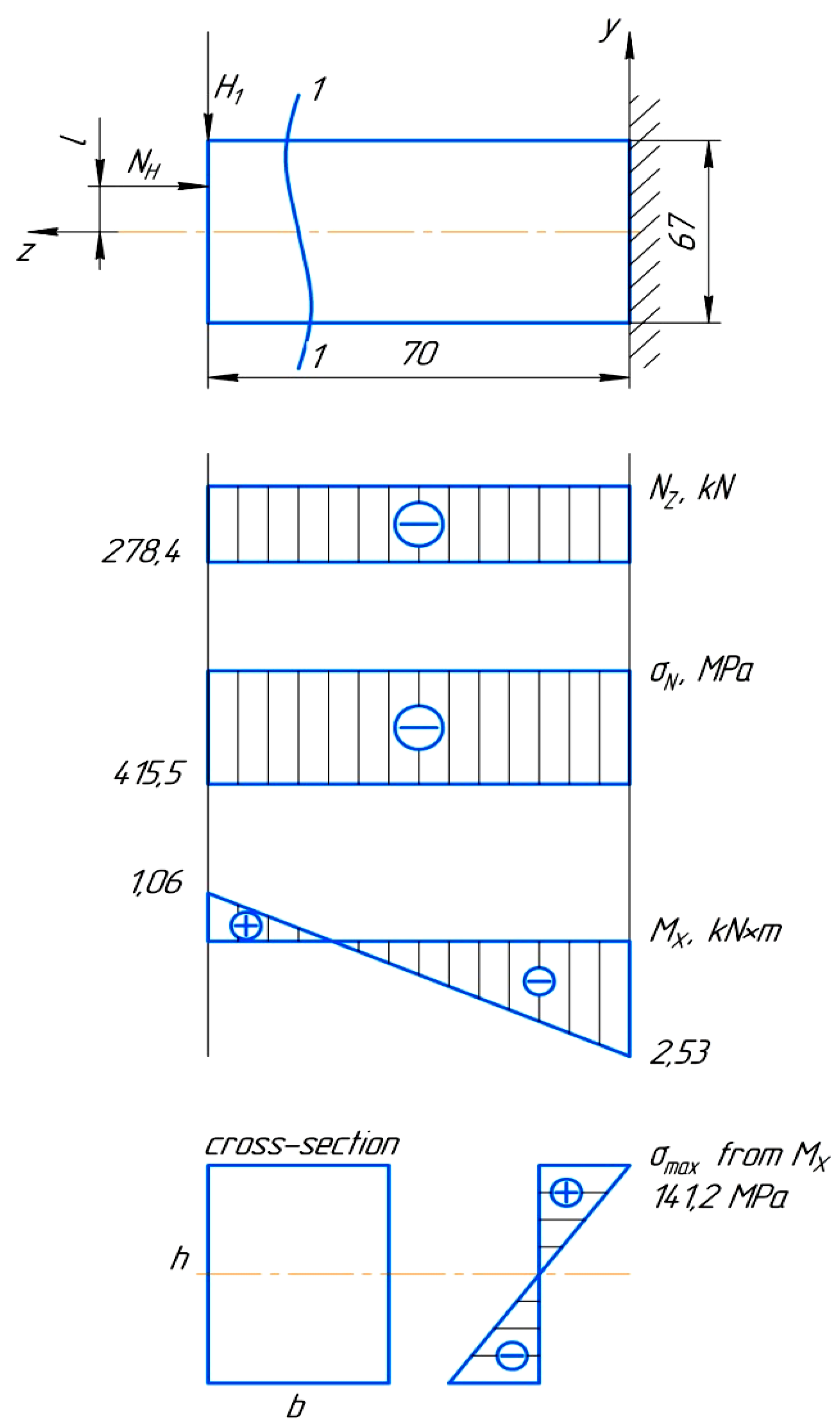
In
Figure 11a,
NH is the vertical reaction of the rails (on the left wheel) and
H1 is the lateral pressure. After calculating the moments of forces and stresses acting in the wheel, curves
Nz,
σN, and
Mx were made (
Appendix B;
Figure A1).
The values of the generated stresses in the contact zone of the wheel were calculated while considering the action of the longitudinal
NH and transverse
forces (
Figure 12) via Equation (16):
where
represents voltages from the longitudinal force (
) and
represents voltages from the transverse force (
).
where
is a longitudinal force,
F is the cross-sectional area,
is the tension emerging from the bending moment as a result of longitudinal and transverse forces,
is the bending moment,
is the moment of inertia, and
y represents the cross-section coordinates.
In an arbitrary cross-section, the longitudinal force was determined by:
Further, the operating normal voltages were clarified, quantitative values are described in the text. It was established that the contact between the wheel and the rail did not occur along the line, but there was a contact spot of 8–13 mm. For the study, the spot was 10 mm. Accordingly, the normal stress was 415.5 MPa. The (−) sign indicates that the stress formed a compression of the wheel material structure. The contact area of the wheel flange tread F = 670 mm2 = 0.00067 m2.
The bending moment
Mx was formed according to principle (17):
where
is the moment of inertia for a rectangular cross-section relative to the
x-axis (18).
At h = 67 mm and b = 10 mm, Ix = 2.51 × 10⁻⁷ m4 and y = 0.0335 m; then, the unknown was 141.2 MPa (18). This means that at of the bending moment, the total stress σ = 556.7 MPa.
With a decrease of the contact area during the wear of the wheel tread surface in real operating conditions by 2 mm (; F = 670 mm2), the value of the normal stress significantly increased (= −428.31 MPa).
With a change in the worn contact area, the moment of inertia along the
x-axis
= 2.29 × 10
−7 m
4 also changed, the stresses acting through the bending moments
= 154.77 MPa increased, and the total stress in the contact spot
σ = 543.08 MPa (
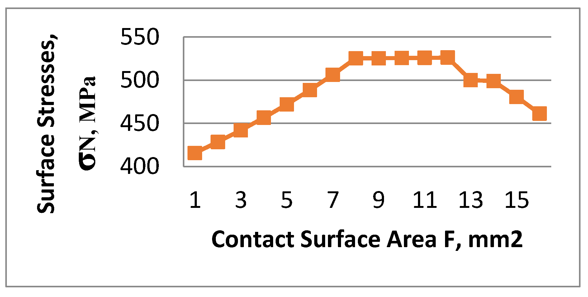
Figure 12).
Analysing the graph (
Figure 12) shows that with an increase in the wear area of the wheel tread surface, the stresses that formed fatigue wear increased. However, an increase in the stress
σN was observed at
σN = 583 MPa, which corresponding to the contact surface area of
F = 8 mm
2. This phenomenon describes the progressive wear of the wheel contact surface, which is probabilistic [
64]. With an increase in the wear area in the range of
F = 8–12 mm
2, stress stabilization was observed at
σN = 557 MPa. This range describes the process of an increased wear area, comparable to the surface of the entire tread diameter. Consequently, the wear area was so large that it replaced the tread surface and the stress decreased in magnitude. However, despite the decrease
σN, we observed the chipping and deformation of the tread surface. This was due to the wear of the hardened surface layer and, accordingly, a decrease in the physical and mechanical properties of the metal. In the course of the research, the dependences of the polynomial law of changes in normal stresses—
σN = −1.5021
F2 + 29.959
F + 371.87 and
= 1.3749
F2 + 8.1023
F + 132.63—on bending stresses on the wear of the wheel contact surface were established.
Therefore, the results of the experiments showed that when the contact area decreased by (20 mm), the stress value increased by 4.5%.
It was established that in real operating conditions, the tread surfaces of wheelsets intensively wear out. Wear causes the degradation of the tread surface in its structural parameters (fatigue wear) and changes in spatial shape, design geometry, and surface roughness .
9. Conclusions
The following conclusions were made after conducting research using a wide range of mathematical analysis tools:
The design, technological, and operational indicators of the reliability and durability of car wheels were determined. It was established that plasma-laser restoration using the modern material of 15Ni17N12V3F improved the phase structure and increased the wear resistance of the wheel and the comb.
It was established that the dynamic qualities of cars in the horizontal plane could be determined mainly by the characteristics of the rolling profile of wheel pairs and the parameters of the wheel–rail contact (contact positions, sliding speeds between the surfaces of the wheel and rail, and the condition of the rail track), as well as tribological properties such as contact pressure, slippage, surface condition, and temperature regime.
A systematic approach was developed to investigate the causal relationship between changes in the wear of the contact surface of the wheel due to dynamic loads and the intensity of the deviation of the contact spot from the axis of the vehicle trajectory in curved sections.
It was established that the durability of railway wheels depended on a progressive increase in contact stresses σN, which determined the boundaries of the area of the calculated deviation of the contact spot of the wheel profile from the axial trajectory.
The maximum permissible wear values of the contact area and the wheel crest of I = 1.9 mm were justified.
The factors of the progressive increase in contact stresses σN, which determined the boundaries of the area of deviation of the contact spot of the wheel profile from the axial trajectory of movement, were determined and justified.
In real operating conditions, we determined that the tread surfaces of wheelsets are intensively wearing out. This causes degradation of the tread surface in its structural parameters and changes in spatial shape, design geometry, and surface roughness.
It was proven that the vertical static load Pst on the wheel changes as a result of the wear of the tread surface and wheel flange. The change in the utilization factor of the load capacity of the car was found to affect the amplitude of cyclic forces during operation. As a result, the useful traction forces acting at a certain negative angle to the wear area formed the moments of resistance forces. To solve this problem, the dependences of the static load Pst on the utilization factor of the railcar load capacity and the gross weight mgr of the car weight were established. Classical calculations for real operating conditions, taking dynamically unstable loads into account, were integrated.
It was calculated that when moving along curves, as well as on straight sections of the track, we could observe wheel sliding, which led to shock load and, as a result, the chipping of places affected by contact fatigue cracks and the formation of cavities on the tread surface.
The criteria of forecasting, considering contact cycles in the formation of fatigue stresses at the stage of defect origin, were substantiated. The process of the dynamic interaction of the contact worn profile of a wheel with a railway rail was investigated. Polynomial equations were proposed to substantiate the optimal design and technological parameters of designing a railway carriage wheel. The dependences of the change in static load on the utilization factor of the railway carriage load capacity were established. The dependences of changes in fatigue stresses on the calculated deviation of the contact area during wheel wear were established. It was confirmed that the stress concentration under cyclic loads was formed in the ferritic layers of the material structure before the appearance of wear.
It was established that the tread surface of the wheel and the disk at the base of the shaft neck work under conditions of large alternating loads that occur in a short period. The concentration of critical stresses was found to have a local character and be short in time. The contact section of the wheel operating with stresses σF = 85.347–123.025 MPa under the condition of strength σF ≤ [σF] was shown to operate within the permissible limits.
It was established that the contact between the wheel and the rail did not occur along the line, but there was a contact spot of 8–13 mm. With an increase in the wear area in the range of F = 8–12 mm2, stress stabilization was observed at σN = 557 MPa. This range describes the process of an increased wear area comparable to the surface of the entire tread diameter. Therefore, the results of this study showed that when the contact area decreased by (20 mm), the stress value increased by 4.5%.
According to our conducted metallographic studies, it was found that the selected nickel-based reduction material, 15Ni17N12V3F, has strong physical and mechanical properties. It has been established that this material, 15Ni17N12V3F, forms an optimal martensite phase structure that increases the wear resistance of a wheel under dynamic and shock loads. Additionally, during laser restoration, this material provides a balance of tensile and compressive stresses during the thermal expansion of the wheelbase.


 ,
, 


