Article

Pulsed Waterjet Roughening of Cast Iron and Aluminum Alloy for Automotive Engine Remanufacturing with Plasma Transferred Wire Arc Coating

Department of Mechanical and Aerospace Engineering, Carleton University, 1125 Colonel By Dr, Ottawa, ON K1S 5B6, Canada
*
Author to whom correspondence should be addressed.
Coatings 2020, 10(9), 864; https://doi.org/10.3390/coatings10090864
Submission received: 8 August 2020 / Revised: 28 August 2020 / Accepted: 3 September 2020 / Published: 6 September 2020
(This article belongs to the Special Issue Coatings and Interfaces)

Abstract

:
This study utilized the high-pressure pulsed waterjet process and paired it with the plasma transferred wire arc technology to develop a novel technique to remanufacture damaged engine cylinder bores. The objective of this research was to eliminate the need for expensive bond-coats such as Ni-Al by optimizing the surface roughness profile of the substrate to provide acceptable mechanical bonding between the coating and the substrate. In this study, a high chrome stainless steel wire (Metcoloy #2) was plasma spray coated on a wide range of pulsed waterjet roughened surface profiles generated on grey cast iron and cast aluminum A380 alloy, the two most common engine materials. The pulsed waterjet greatly increased the adhesion strength between the substrates and the Metcoloy #2 coating. The increase in adhesion strength is a result of the formation of favorable mechanical anchoring points. Optimal pulsed waterjet parameters were determined to avoid the production of a copious roughness profile which resulted in a coating that mirrored the roughened surface profile. Additionally, if the roughness profile produced by the pulsed waterjet was insignificant the coating was removed in its entirety during detachment-based failure.

1. Introduction

Nowadays fuel efficiency and emission control have changed the way diesel and gasoline engines have been designed and remanufactured in the automotive industries. In many cases, older and less fuel-efficient models of auto-engines are being upgraded to better operating functionality. In doing so, automakers are remanufacturing and giving a new life to the engines that would otherwise be decommissioned and scrapped at a cost [1]. The remanufacturing of worn-out automotive engines can reduce CO2 emissions by up to 80% when compared with the energy required to produce a new equivalent engine [2]. Automotive manufacturers such as Fiat, Ford, and Caterpillar are currently remanufacturing their worn-out engine cylinder bores by using the plasma transferred wire arc (PTWA) coating process to give new life to these engines. To improve the coating-substrate bond strength, the process also involves the deposition of an expensive Ni-Al pre-bond coat. On one side, the pre-bond coat is important to ensure the coating-substrate bond strength in the engine bore is high enough to be used under engine operating conditions. On the other hand, the process complexity and high price-tag associated with this pre-bond coat on many occasions result in the removal and replacement of the worn-out engines [3]. This research work demonstrates the formation of an optimized roughened surface profile by using pulsed waterjet, a simpler, cheaper, and environmentally friendly technique, as a coating strength enhancer and as an alternative to the conventional Ni-Al pre-bond coat step, before the final PTWA coating.
The basis of waterjet technology is the deliverance of high energy water to an extremely small area [4,5]. As the high energy water impacts the surface of the target area it disintegrates the material. The pulsed waterjet technique can be described as the breaking of a continuous stream of water to produce slugs, discrete packets of water responsible for the disintegration of the target material. The greater the energy associated with these slugs, the greater the amount of disintegration at the impact surface [6]. It is the disintegration of the impact surface which results in the roughened surface profile.
The PTWA process is being used to resurface worn-out engine cylinder bores and has enabled the use of soft lightweight materials such as aluminum by coating the cylinder bores with harder materials such as steel [7,8]. PTWA spraying of metallic coating materials results in the creation of a lamellar microstructure on the surface. This lamellar structure consists of splats which are a result of molten metal droplet hardening as they hit the target surface. These splats bond and build-up on the surface, with several layers of splats forming the thermal spray coating [9].
Studies have been conducted to determine the adhesion bond strength of mechanically interlocked spray coatings and substrates. However, there is a lack of research on using the pulsed waterjet process to develop an ideal surface roughness profile for mechanical interlocking between PTWA coatings and substrates. Samson et al. [10] investigated the bond strength of pure aluminum powder cold sprayed onto a pulsed waterjet roughened aluminum 6061-T6511 substrate. They proposed that increased adhesion strength between the coating and substrate may be a result of increased anchoring features and increased roughness. Knapp et al. [11] reported the plasma sprayed MCrAlY coating-substrate bond strength as high as 70 MPa after roughening the Inconel 718 and Mar-M 509 substrates by the waterjet process. Bobzin et al. [12] compared the adhesion strength between a PTWA low carbon steel coating on Al-6060 surfaces geometrically cut and high-pressure waterjet roughened. The cutter produced a dovetail surface profile with an average adhesion strength of 58 MPa compared to 48 MPa for the waterjet process. Grit blasting with Al2O3 particles was used to roughen the surface of cast iron and Al-Si alloys to promote mechanical interlocking between the PTWA coating and the substrate [13]. The authors reported the adhesion strength between the PTWA steel coating and grit blasted substrates ranged from 40–60 MPa and 50–70 MPa for aluminum and cast iron, respectively.
The goal of this research project was to optimize the surface roughness of cast iron and cast aluminum substrates using high-pressure pulsed waterjet technology to produce a coating- substrate adhesion strength greater than 30 MPa, which is required for cylinder bore liners [14]. With the optimized surface roughness of the cast iron and aluminum substrates using the high-pressure pulsed waterjet technology, old worn engine blocks can be remanufactured using this technique. Not only the reduced production costs will entice the automotive industry to implement this new technique, but also the development of a more sustainable remanufacturing process will assist in the reduction of the environmental footprint by the automotive industry.

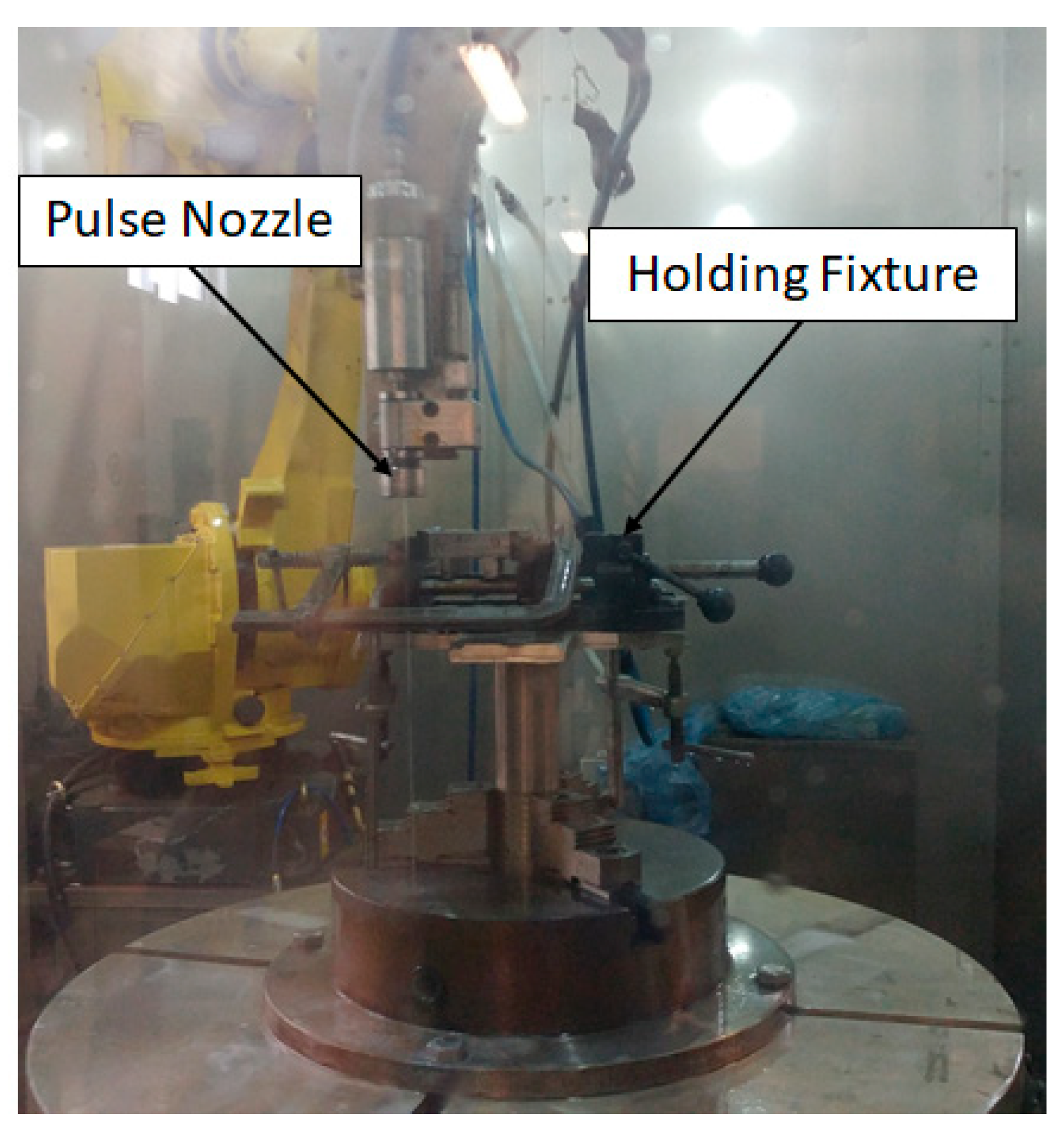
2. Materials and Methods

Grey cast iron (GCI) and aluminum A380 substrates were die-cast in larger molds to avoid warping during solidification. The compositions of the two alloys as provided by the suppliers are presented in Table 1. Before waterjet roughening, the cast substrates were machined to improve the surface finish and cut into smaller coupons. A total of 10 GCI and 9 A380 coupons was generated. Each of the coupons was subjected to different pulsed waterjet parameters to produce different surface roughness profiles.
The parameters used to waterjet the two materials are as presented in Table 2 and an image of the pulsed waterjet nozzle setup used in this study is shown in Figure 1. Throughout the experiment, the water pressure remained constant at 34.5 MPa and the roughness value of the pulsed waterjet samples was altered by changing the nozzle transverse velocity. The standoff distances for the GCI and A380 were 25.4 and 31.75 mm, respectively. Different standoff distances were needed as cast iron and aluminum alloy have different material properties. The roughness value of each coupon after pulsed waterjet was measured with a DekTak XT (Bruker, Billerica, MA, USA) profilometer over a 10 mm by 10 mm area using a scan resolution of 1.66 µm per point, a stylus force of 3 mg, and a scan speed of 500 µm/s. The Vision64 software used to generate a 3-D area roughness map determined the average roughness value (Ra) over the 10 mm by 10 mm cross sectional area by taking an average of the 60,0000 measurements taken for each sample.
The PTWA machine used was a Sulzer Metco and the feedstock material used for the PTWA spray coating process was Metcoloy #2 wire with a composition of C 0.25, Cr 13, Si 0.5, and Ni 0.5 (wt.%), which is commonly used in applications such as cylinder liners, pistons, valve stems, pump plungers, and crankshaft bearings [15]. The standoff distance used during coating was 150 mm. The coating was applied in 12–15 passes over the substrate to obtain a final coating thickness of 0.6 mm. Microstructural characterization was performed using a Zeiss GeminiSEM 500 scanning electron microscope (SEM) (Zeiss, Jena, Germany).
A portable automatic pull-off adhesion gauge was used to perform pull-off testing on the 10 GCI and 9 A380 roughened and coated substrates. Three 10 mm dollies were evenly distributed and adhered to each of the coated substrates. This allows three pull-off tests to be performed for each roughness profile showing the reproducibility of the pull-off adhesion strength results. The FM-1000 adhesive (Cytec, Havre De Grace, MD, USA) used for testing provided a bond strength greater than 90 MPa. The adhesion strength for each coupon was determined by taking the average of three pull-off tests.

3. Results and Discussions

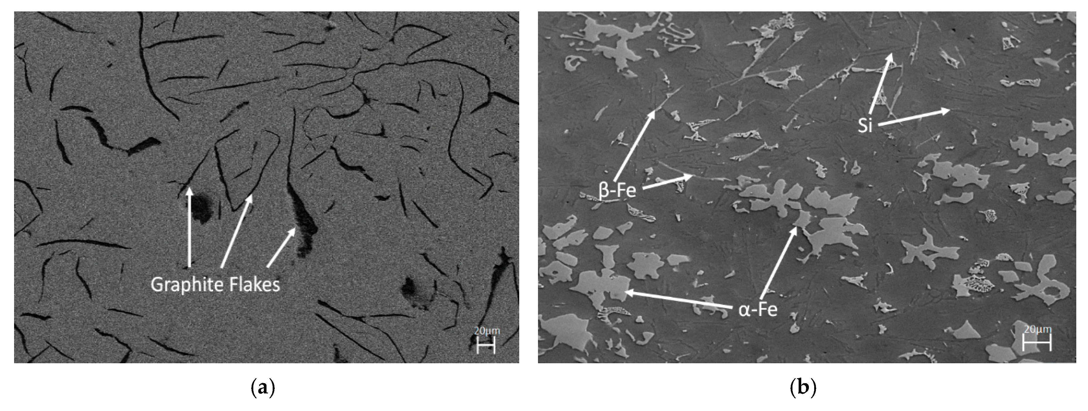
3.1. Overview and Microstructures of the Substrates

The SEM images in Figure 2 represent the initial microstructures of the GCI and A380 substrate materials. The microstructure of GCI shows a predominantly pearlitic matrix with dark lamellar three-dimension graphite flakes as two-dimensional wormlike features. The length of the graphite flakes ranged between 10 to 250 µm and the widths ranged between 10 to 20 µm. The A380 substrate is a hypoeutectic material consisting of three visible primary phases surrounded by an aluminum matrix. The α-Fe phase has a chemical composition of Al15Si2(FeMn)3 and appears polyhedral or Chinese script in shape [16]. The β-Fe phase has a chemical composition of Al5FeSi and is a three-dimensional platelet that appears like a needle on the two-dimension surface [16]. Both the α-Fe and β-Fe intermetallic features ranged in size from 10–100 µm. The final phase visible in the A380 microstructure is the faint Si wormlike phase which had lengths ranging between 10–50 µm and a width ranging between 1–5 µm [17].

3.2. Defects in the Substrates

Defects in the two substrate materials were studied that may impact the performance of the material during pulsed waterjet surface roughening. The major defect observed was the pores produced by shrinkage and gas entrapment during the casting process. The pores in the GCI and A380 substrate materials are shown in Figure 3 and ranged from 1–4 µm in size. These small defects are initiation sites for which crack formation, propagation, and material removal occurs resulting in the roughened surface profile produced by the pulsed waterjet process.

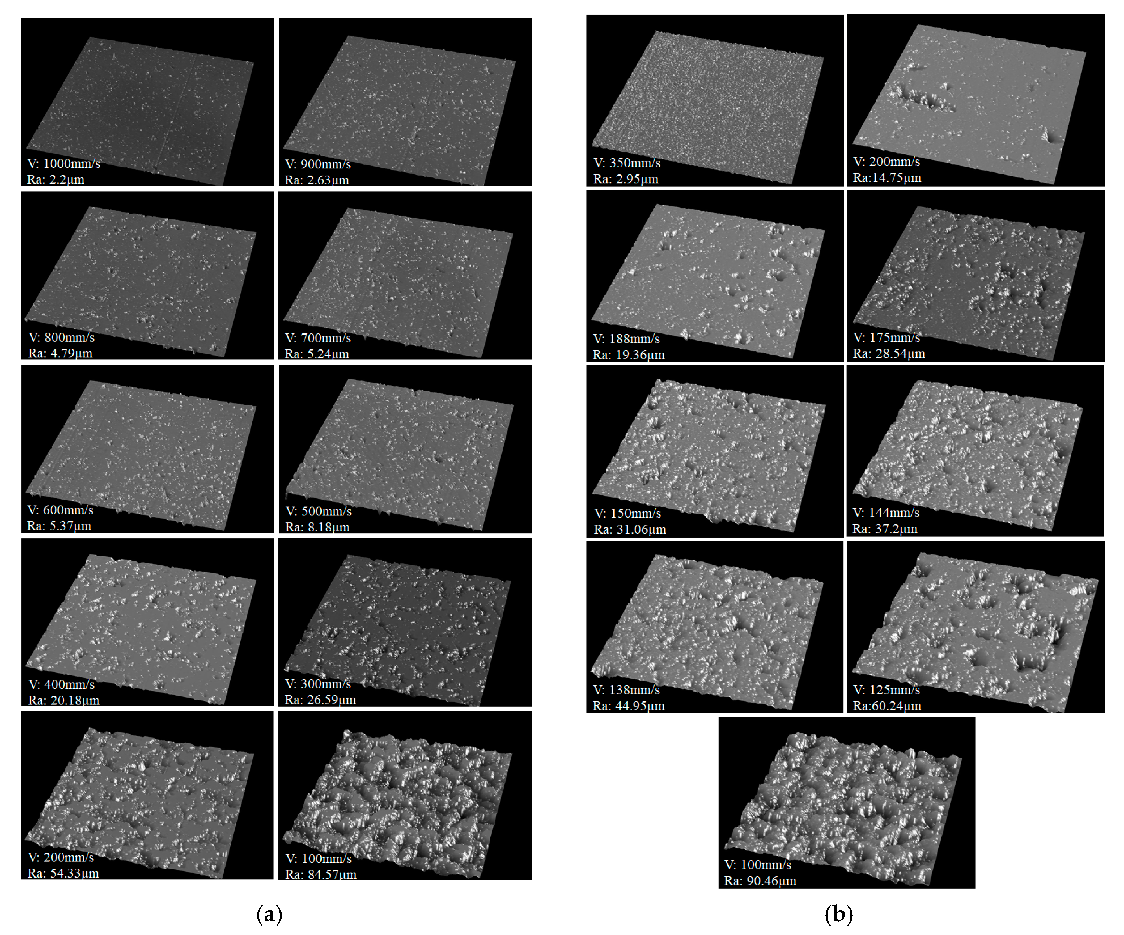
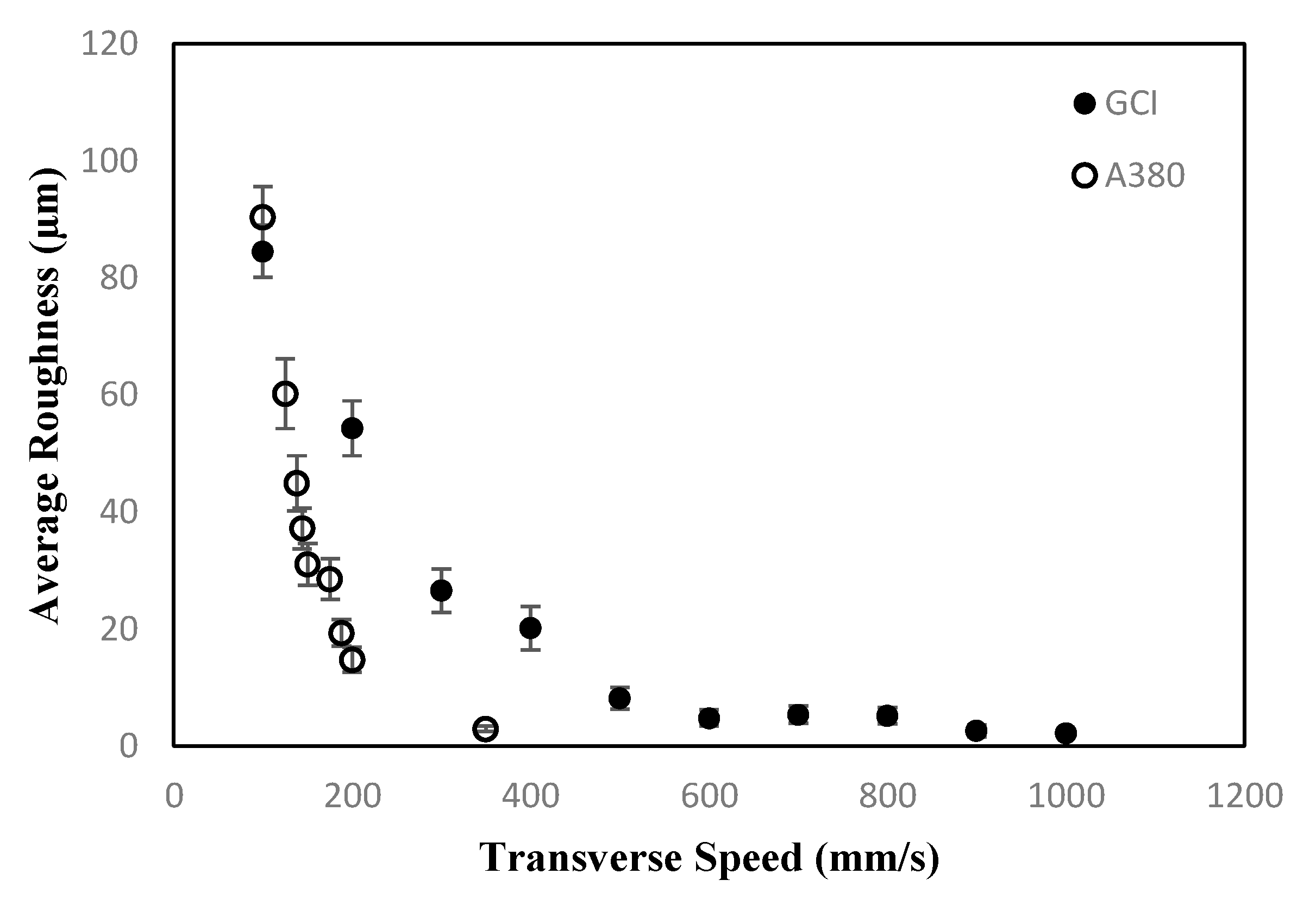
3.3. Pulsed Waterjet Roughening

The pulsed waterjet used in this study relies on oscillations of an ultrasonic probe tip (microtip) in the nozzle. These oscillations produce ultra-high-frequency vibrations that act on the waterjet stream to produce thousands of pulses per second as the water passes through the nozzle. As the flow of water is modulated non-continuous discrete packs of water known as slugs are produced.
The three-dimension area scans taken for each pulsed waterjet roughened coupon are presented in Figure 4. These scans calculate the average surface roughness (Ra) and give a more detailed view of the coupon’s roughened surface profile.
Studying these images reveals that the average roughness value increased as the pit depth and density increased. The pits are blunt in shape and isolated from each other. The distribution of the pits is random due to the randomness associated with the developed water-hammer head in the pulsed waterjet, and the randomness of the phases and other microstructural features in the material. In the case of the GCI, the pits in the roughened surface are a result of cracks forming and coalescing in the graphite flakes. When the pulsed waterjet pressure applies stress on the relatively brittle GCI surface, load-induced fracture occurs by crack formation and propagation in the graphite flakes [18]. For the softer and more ductile A380, the surface profile which formed during pulsed waterjet is a result of a combination of crack coalescing, surface erosion, and plastic deformation [19].
Figure 5 shows the correlation between transverse velocity and average surface roughness generated for the GCI and A380 samples. The trends in the graphs show that the surface roughness value decreased with increasing transverse velocity for both substrate materials. As the transverse velocity of the pulsed waterjet nozzle decreased, the dwell time of the pulsed waterjet stream on the target area increased. The increased dwell time resulted in more high-pressure water hammer pulses bombarding the target area which in turn caused an increased amount of fracture, plastic deformation, and erosion on the surface. The roughness values of the GCI ranged from ~2.2 to 85 µm, and the roughness of the A380 ranged from ~3 to 90 µm.

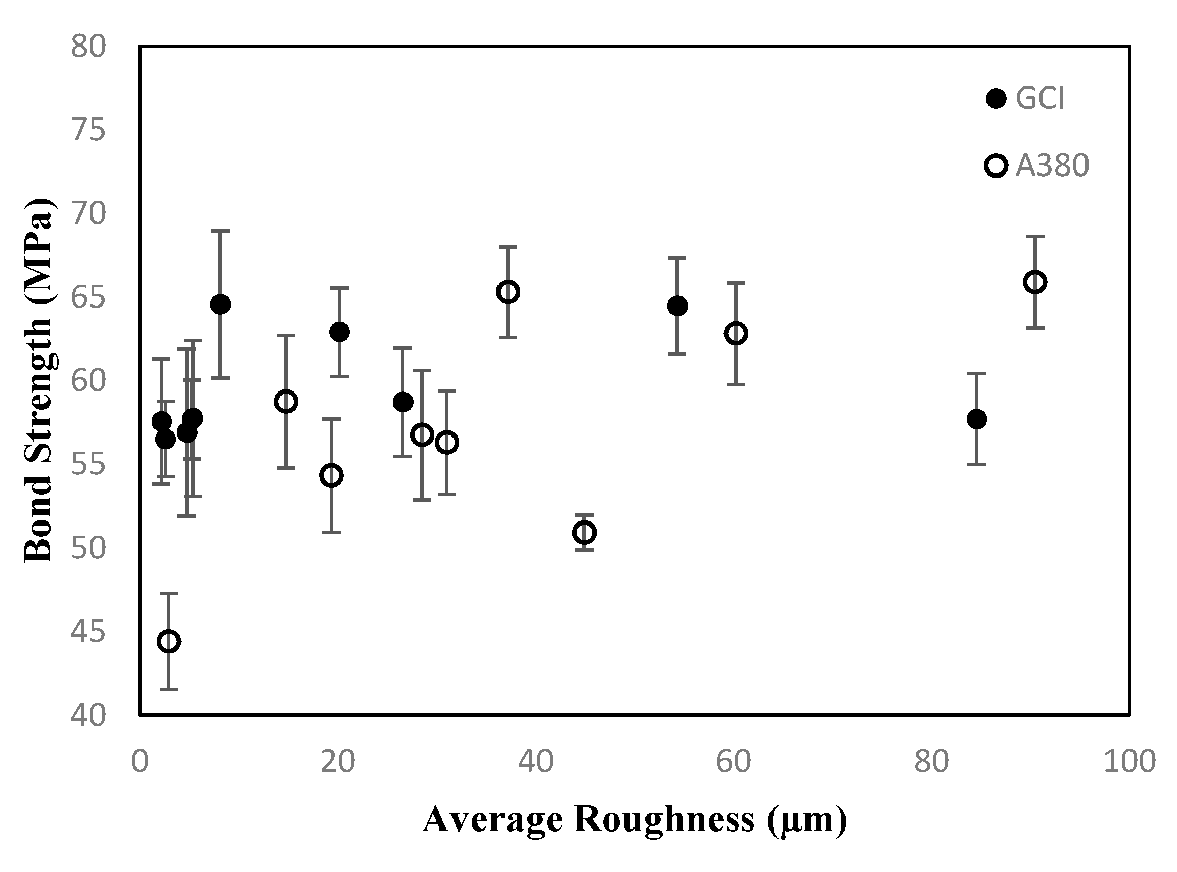
3.4. Pull-off Adhesion Strength

The adhesion strength between the coatings and substrates was determined to be the force required to separate the coating from the substrate. Failure during pull-off adhesion testing can occur in many ways including at the glue which binds the dolly to the coating, adhesively at the interlock between the coating and substrate, cohesively between the splat layers of the coating, or mixed mode which is a combination of glue, adhesive, or cohesive based failure [20]. The adhesion testing of these samples revealed how average surface roughness affected the bond strength between the spray coating and substrate and is plotted in Figure 6 for GCI and A380. Generally speaking, the GCI plasma spray system exhibited higher bond strength than the A380 sample. With a big variation in average surface roughness (2.2 to 85 µm) the bond strength varies within the range from 53 MPa to 66 MPa for GCI. For the A380 plasma spray coated system, there was a larger variation in average surface roughness (~3 to 90 µm) and the bond strength values ranged from 44 MPa to 66 MPa. For A380, the pull-off strength at 2.95 µm roughness is the lowest (~44 MPa) because of the lack of favorable mechanical anchoring sites. There is also a decrease in pull-off strength at a surface roughness value of 44.95 µm for A380 but the pull-off adhesion strength of 51 MPa is still in the recommended range. Therefore, all the measured bond strength values are above the required 30 MPa for cylinder liners and most range between or above the recommended 45 to 55 MPa outlined by Barbezat et al. [14]. Also, it is important to note that for three pull-off adhesion tests conducted for each sample there was little variation in measured pull-off adhesion strength.

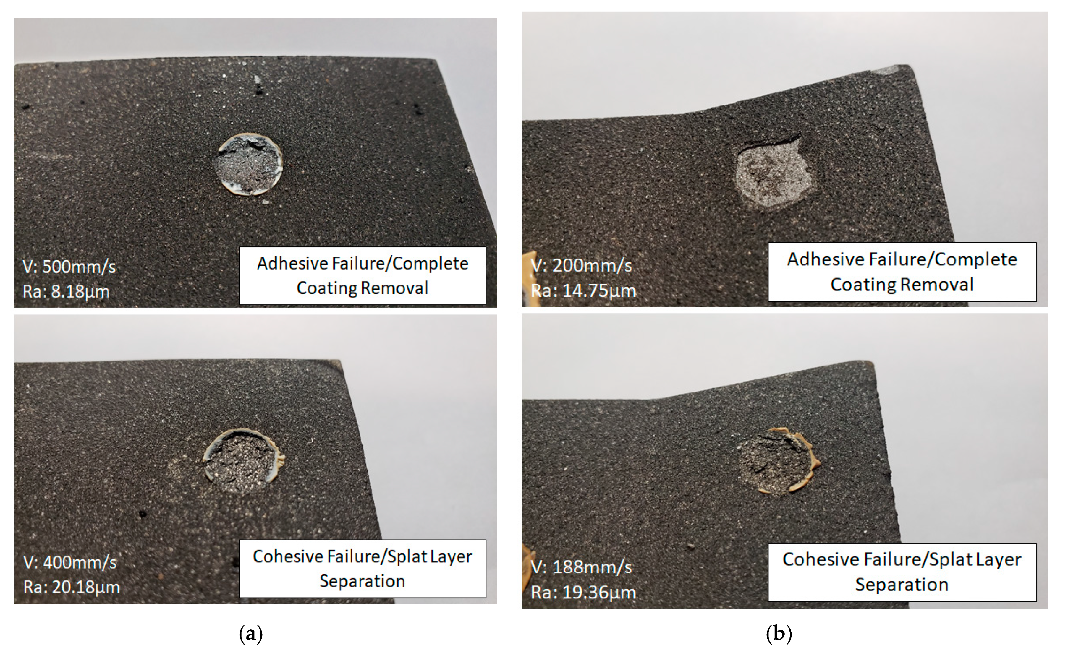
3.5. Coating System Failure and Surface Profile

The substrate-coating combinations studied in this work experienced failure characteristics depending on the surface roughness profile. The failure modes for all the pull-off tests are presented in Table 3. It was noted that for both substrates, when the average surface roughness value was below ~20 µm, the adhesion strength test resulted in an adhesive failure of the coating layer. However, above 20 µm the failure was no longer a clean coating removal and failure occurred cohesively between the coating splat layers. Images of the complete coating removal and splat layer failure types for the GCI and A380 samples are presented in Figure 7. Therefore, an average surface roughness of 20 µm or greater should be considered optimal for adhesion strength between the pulsed waterjet roughened surface and spray coating. This is because if failure does occur, the remaining coating would protect the substrate from the environment.
Another important aspect of the coating system is the surface profile after the coating process. In cases where the average surface roughness exceeded 60 µm the surface profile of the coating mirrored the roughness profile of the substrate. A rough coated surface finish is not desirable and requires additional processes to obtain a suitable finish for the cylinder bore liner application. These processes include additional spray time and material, and additional honing to create the smooth finish required for the piston to slide efficiently and effectively on the cylinder bore wall. Therefore, for this study, the optimum average surface roughening value is considered to be 20–60 µm. It should also be noted that decreasing the roughness value results in increased nozzle velocity and decreased processing time, so a roughness value close to 20 µm is the most favorable.

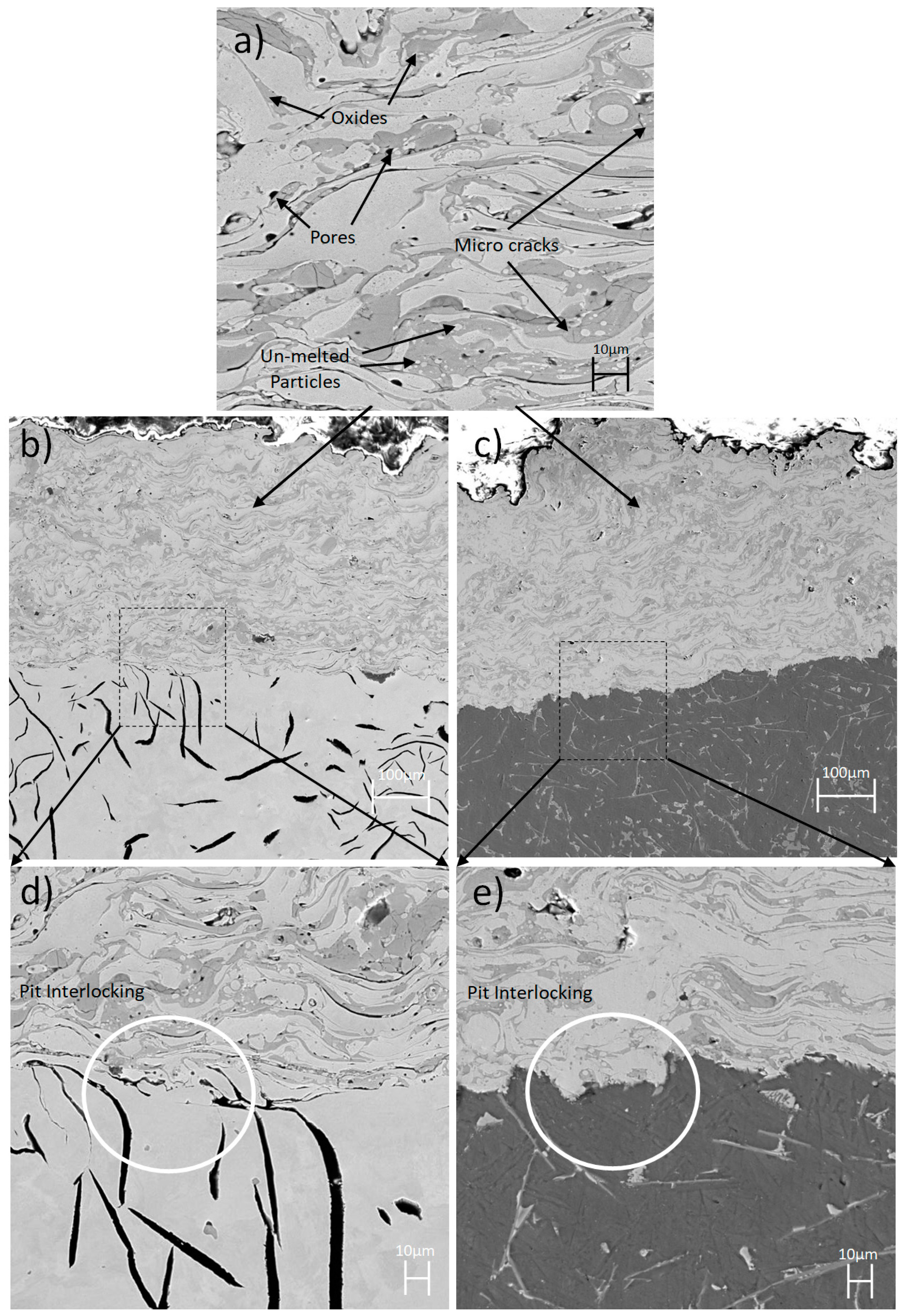
3.6. Substrate-Coating Interface Cross-Sectional Microstructures

The pulsed waterjet roughening processes activated the substrate surface by producing pits that provided a site for mechanical interlocking of the plasma spray coating. The tensile load applied perpendicular to the coating surface attempts to break the mechanical interlock between the coating and the substrate. The pulsed waterjet process does not produce a homogeneous roughened surface, so the ability of a pit to anchor the coating varies on pit shape and size. Microscopy of the interface between the substrate and coating showed that at a microscopic level, the average surface roughness increased as a result of increased pit depth and density. The increased pit depth and density may lead to improved adhesion strength as the surface area and number of mechanical anchoring sites increases. Interestingly, the increased surface roughness does not produce features that disrupt the deposition of the splat material. The top image in Figure 8 shows the typical cross-sectional microstructure of the Metcoloy #2 coating with the pores, micro cracks, oxides, and un-melted particles labeled on the figure. Also Figure 8 shows the mechanical interlocking between Metcoloy #2 coating and roughened GCI and A380 substrates. Upon further examination of the images, the differences between the two roughened substrate surface profiles are identifiable. These differences include pit structure, where the pits in the A380 appear more defined while those in the GCI look more flakey and pit configuration where the pits in the A380 seem more jagged or aggressive, while the pits in the GCI appear more rounded and elongated. Finally, pit sizes such that the pits in the A380 appear to have a smaller width but reach a greater depth than those in the GCI. The increased pit depth leads to improved adhesion strength by increasing the surface area which improves the potential for favorable anchoring sites and increases the extent of the surface which needs to shear for failure to occur.

4. Conclusions

The pull-off adhesion strength between pulsed waterjet roughened grey cast iron (GCI) and aluminum A380 samples, and the plasma transferred wire arc (PTWA) Metcoloy #2 coating was studied to determine the optimal surface parameters. This work points out an alternative and environmentally friendly way to deposit a PTWA coating on an engine bore during re-manufacturing. The conclusions derived from the study are as follows:
  • The average surface roughness of the GCI and A380 increased with decreasing pulsed waterjet nozzle velocity. This is a result of the increased dwell time of the jet in a specific area resulting in more impacts of the high energy water hammer.
  • The roughened surface profile produced by the pulsed waterjet on the GCI is a result of surface erosion, and crack propagation together with coalescing through the brittle graphite flakes. The roughened surface profile produced by the pulsed waterjet on the A380 is a result of crack propagation and coalescing, surface erosion, and plastic deformation.
  • It was observed that for samples with an average surface roughness value greater than 60 µm, the PTWA spray coating mirrored the substrate surface profile. This is disadvantageous as there would be more post processing steps required to produce a satisfactory surface. It was also noticed that above an average surface roughness value of 20 µm the amount of coating which remained on the surface after detachment-based failure increased. This is because the number of favorable anchor points for mechanical interlocking between the substrate and coating increased. This is beneficial because if failure does occur the remaining coating would protect the substrate from the environment. Thus, the optimal average surface roughness for adhesion strength between the substrate and coating is between 20 µm and 60 µm.
  • The bond strength for GCI and A380 with the Metcoloy #2 coating was above the recommended bond strength of 30 MPa for all the tested samples. This means independent of the average surface roughness value; the pulsed waterjet process is an effective surface activator to improve mechanical bonding between the substrate and coating during the plasma transferred wire arc process. Therefore, it can certainly be concluded that during engine remanufacturing, the step associated with the expensive Al-Ni pre-bond coat can be avoided by the much simpler, cheaper, and eco-friendly pulsed waterjet surface roughening process.

Author Contributions

Conceptualization, A.S.K.; Formal analysis, N.O.; Funding acquisition, A.S.K.; Investigation, N.O. and A.S.K.; Methodology, N.O. and A.S.K.; Project administration, N.O.; Supervision, A.S.K.; Writing–original draft, N.O.; Writing–review & editing, A.S.K. All authors have read and agreed to the published version of the manuscript.

Funding

Financial supports from Natural Sciences and Engineering Research Council (NSERC) of Canada and Ontario Centers of Excellence (OCE) are acknowledged.

Acknowledgments

The authors would also like to thank Andrew Tieu and Mohan Vijay of VLN Advanced Technologies Inc. in Ottawa, Ontario, Canada for their support.

Conflicts of Interest

The authors declare no conflict of interest.

References

  1. Bobzin, K.; Ernst, F.; Zwick, J.; Schlaefer, T.; Cook, D.; Kowalsky, K.; Bird, K.; Gerke, D.H.; Sharp, R.E.; Raab, K.R.; et al. Lindon, Thermal spraying of cylinder bores with the PTWA internal coating system. In Proceedings of the ASME 2007 Internal Combustion Engine Division Fall Technical Conference, Charleston, SC, USA, 14–17 October 2007; pp. 697–704. [Google Scholar] [CrossRef]
  2. Lund, R.; Mundial, B. Remanufacturing: The Experience of the United States and Implications for Developing Countries. 1984. Available online: https://pdfs.semanticscholar.org/c87a/1a1b114edd20daf54037433182a6d3ce1e28.pdf (accessed on 15 May 2020).
  3. Cook, D.; Verpoort, C.; Kowalsky, K.; Dicks, R. Thermal spray of cylinder bores with the ford PTWA process, In Proceedings of the Zylinderlaufbahn, Hochleistungskolben, Pleuel. Tagung, München, Germany, 16 September 2003; pp. 151–158. [Google Scholar]
  4. Hashish, M. Abrasive jets; WJTA: St. Louis, MO, USA, 1995; pp. 4.1–4.52. [Google Scholar]
  5. Kim, T.J.; Labus, T.J. Influence of basic jet parameters and physics of abrasive water jet cutting. Proc. WJTA 1995, 3, 45. [Google Scholar]
  6. Zelenak, M.; Foldyna, J.; Scucka, J.; Hloch, S.; Riha, Z. Visualisation and measurement of high-speed pulsating and continuous water jets. Measurement 2015, 72, 1–8. [Google Scholar] [CrossRef]
  7. Zou, J. Characterization of thermal spray coatings on aluminum engine bore. Master’s Thesis, University of Windsor, Windsor, ON, Canada, May 2016; pp. 1–4. [Google Scholar]
  8. Gérard, B. Application of thermal spraying in the automobile industry. Surf. Coatings Technol. 2006, 201, 2028–2031. [Google Scholar] [CrossRef]
  9. Fauchais, P.L.; Heberlein, J.V.; Boulos, M.I. Thermal Spray Fundamentals: From Powder to Part; Springer: New York, NY, USA, 2014. [Google Scholar] [CrossRef]
  10. Samson, T.; Macdonald, D.; Fernández, R.; Jodoin, B. Effect of Pulsed Waterjet Surface Preparation on the Adhesion Strength of Cold Gas Dynamic Sprayed Aluminum Coatings. J. Therm. Spray Technol. 2015, 24, 984–993. [Google Scholar] [CrossRef]
  11. Knapp, J.K.; Taylor, T.A. Waterjet roughened surface analysis and bond strength. Surf. Coatings Technol. 1996, 86, 22–27. [Google Scholar] [CrossRef]
  12. Bobzin, K.; Ernst, F.; Zwick, J.; Schlaefer, T.; Cook, D.; Nassenstein, K.; Schwenk, A.; Schreiber, F.; Wenz, T.; Flores, G.; et al. Coating Bores of Light Metal Engine Blocks with a Nanocomposite Material using the Plasma Transferred Wire Arc Thermal Spray Process. J. Therm. Spray Technol. 2008, 17, 344–351. [Google Scholar] [CrossRef]
  13. Barbezat, G.; Wuest, G. Advantages for automotive industry of plasma spray coating of Ai–Si cast alloy cylinder bores. Surf. Eng. 1998, 14, 113–116. [Google Scholar] [CrossRef]
  14. Barbezat, G.; Keller, S.; Wuest, G. Internal plasma spray process for cylinder bores in automotive industry. ASM Int. 1998, 11–19. [Google Scholar]
  15. Sulzer Metco. Technical Bulletin # 10-023; Westbury, NY, USA, 2000. [Google Scholar]
  16. Ebhota, W.S.; Jen, T.-C. Intermetallics Formation and Their Effect on Mechanical Properties of Al-Si-X Alloys. Intermet. Compd. Form. Appl. 2018, 21–41. [Google Scholar] [CrossRef] [Green Version]
  17. Tang, P.; Li, W.; Wang, K.; Du, J.; Chen, X.; Zhao, Y.; Li, W. Effect of Al-Ti-C master alloy addition on microstructures and mechanical properties of cast eutectic Al-Si-Fe-Cu alloy. Mater. Des. 2017, 115, 147–157. [Google Scholar] [CrossRef]
  18. Selvan, M.C.P.; Raju, N.M.S.; Rajavel, R. Effects of Process Parameters on Depth of Cut in Abrasive Waterjet Cutting of Cast Iron. Int. J. Sci. Eng. Res. 2011, 2, 1–5. [Google Scholar]
  19. Gent, M.; Menendez, M.; Torno, S.; Toraño, J.; Schenk, A. Experimental evaluation of the physical properties required of abrasives for optimizing waterjet cutting of ductile materials. Wear 2012, 284, 43–51. [Google Scholar] [CrossRef]
  20. Lima, C.R.C.; Guilemany, J.M. Adhesion improvements of Thermal Barrier Coatings with HVOF thermally sprayed bond coats. Surf. Coat. Technol. 2007, 201, 4694–4701. [Google Scholar] [CrossRef]
Figure 1. Pulsed waterjet system setup.
Coatings 10 00864 g001
Figure 2. SEM images of the substrates: (a) grey cast iron (GCI) and (b) aluminum A380.
Coatings 10 00864 g002
Figure 3. SEM images of pores in the substrates: (a) GCI and (b) A380.
Coatings 10 00864 g003
Figure 4. Three dimensional scans of pulsed waterjet roughened (a) GCI and (b) A380 surface profiles for a 10 mm by 10 mm area.
Coatings 10 00864 g004
Figure 5. The effects of nozzle transverse velocity on surface roughness of GCI and A380.
Coatings 10 00864 g005
Figure 6. The adhesion strength of the Metcoloy #2 plasma spray coating on the GCI and A380 substrates.
Coatings 10 00864 g006
Figure 7. Surfaces after pull-off test of the Metcoloy #2 plasma spray coating on the (a) GCI and (b) A380 substrates showing complete coating removal and partial splat layer removal.
Coatings 10 00864 g007
Figure 8. Cross-sectional SEM images showing the splat layers of the PTWA coating (a), profile of pit interlocking between the (b) Metcoloy #2 and GCI and (c) Metcoloy #2 and A380, and magnified images of pit interlocking between the (d) Metcoloy #2 and GCI and (e) Metcoloy #2 and A380.
Coatings 10 00864 g008
Table 1. Compositions of substrate materials as provided by the suppliers.
Composition Grey cast iron (GCI)Composition A380
ElementWeight Percentage (wt.%)ElementWeight Percentage (wt.%)
C2.8–3.3Si7.5–9.5
Si1.2–1.7Cu3.0–4.0
Mn0.8–1.2Femax 1.3
Pmax 0.15Mnmax 0.5
Smax 0.12Nimax 0.5
Mgmax 0.1
Znmax 3.0
Table 2. Pulsed waterjet parameters used to roughen the GCI and A380 substrates.
Substrate MaterialFrequency (kHz)AmplitudeOverlap Between Pass (mm)Nozzle Diameter (mm)Water Pressure (MPa)Standoff Distance (mm)Nozzle Transverse Velocity (mm/s)
GCI4075%0.1134.525.4100–1000
A3804075%0.1134.531.75100–350
Table 3. GCI and A380 adhesion strength measurements and failure modes.
GCI Adhesion ResultsA380 Adhesion Results
Average Roughness (µm)Pull-off Adhesion Strength (MPa)Failure ModeAverage Roughness (µm)Pull-off Adhesion Strength (MPa)Failure Mode
2.253.25 ± 3.74Adhesive2.9544.40 ± 3.17Adhesive
2.6359.12 ± 2.26Adhesive14.7558.73 ± 3.67Adhesive
4.7955.79 ± 4.98Adhesive19.3654.32 ± 3.80Cohesive
5.2459.97 ± 2.35Adhesive28.5456.74 ± 4.72Cohesive
5.3761.82 ± 4.65Adhesive31.0656.29 ± 4.22Cohesive
8.1860.39 ± 4.40Adhesive37.265.28 ± 4.58Cohesive
20.1861.14 ± 2.64Cohesive44.9550.91 ± 4.60Cohesive
26.5957.69 ± 3.24Cohesive60.2462.81 ± 4.67Cohesive
54.3365.62 ± 2.85Cohesive90.4665.90 ± 3.88Cohesive
84.5759.77 ± 2.71Cohesive

