Letter

Microstructure and Wear Resistance of WC and High Chromium Cast Iron Hardfacing Layers

1
Guangdong Provincial Key Laboratory of Metal Toughening Technology and Application, Guangzhou 510651, China
2
Institute of Materials and Processing, Guangdong Academy of Science, Guangzhou 510651, China
3
School of Materials Science and Engineering, Chang’an University, Xi’an 710061, China
*
Author to whom correspondence should be addressed.
Coatings 2020, 10(9), 852; https://doi.org/10.3390/coatings10090852
Submission received: 18 July 2020 / Revised: 21 August 2020 / Accepted: 24 August 2020 / Published: 31 August 2020

Abstract

:
The WC and high chromium cast iron (HCCI) welded layers were prepared on Q235 low carbon steel by hardfacing technique in order to improve high-temperature performance. The microstructure and mechanical properties of the welded layer were investigated. It was found that Fe3W3C is the major strengthening phase of the WC welded layer. Furthermore, a high-temperature three-body abrasive wear experiment was designed and conducted on the welded layers. The results show that the wear resistance of the WC welded layer was much better than that of the HCCI welded layer at both room and high temperatures. During the high-temperature abrasive wear process, the Fe3W3C phase can effectively strengthen the matrix and hence, contribute to improved wear resistance.

1. Introduction

Q235 low carbon steel has been widely used as structural material due to its good plasticity and welding performance. However, low hardness and poor wear resistance, especially at elevated temperatures, limit its application at severe wear conditions. Thus, surface hardening and coating techniques have been applied to improve the wear resistance of Q235 steel [1,2,3].
Among all the existing techniques, hardfacing is one of the most attractive methods due to its exceptionally low cost, high hardness of welded layer, excellent interfacial bonding force, and low residual stress [1,3,4,5]. It should be noted that hardfacing can not only repair damaged workpieces but also form a cladding metal layer with excellent properties, such as wear resistance, heat resistance, or corrosion resistance on the surface of the workpiece. The properties of the surfacing layer are controlled by the compositions of the surfacing electrode. For instance, a high-manganese steel surfacing electrode was used to obtain a fully austenitic layer with high work-hardening rate, high toughness, and good wear resistance [6]. Furthermore, ceramic particles, such as WC, TiC, and SiC, were introduced to the surfacing electrodes [2,4,7,8,9]. The ceramic reinforced welded layer can be applied to the strongly worn parts, such as concrete mixer blades, high-speed sand mixing boxes, and bulldozers. It is noted that WC is a favorable reinforcement in steels due to its good wettability with the matrix [2,10,11]. Furthermore, it is expected that the WC-containing surfacing layer can also be applied to workpieces that service at high temperatures. However, compared to the room-temperature properties [1], the high-temperature properties of the WC welded layer have received less attention in the literature.
In this study, the WC welded layer and high chromium cast iron (HCCI) welded layer were fabricated on a low carbon steel matrix (Q235) by a continuous multiple-layer surfacing technique. The microstructure of the welded layers was investigated. The hardness of the welded layers was measured at room and high temperatures. Furthermore, a three-body abrasive wear resistance test setup was designed to evaluate the wear properties of the welded layer at high temperatures and room temperature.

2. Experimental Procedures

2.1. Materials and Microstructure Observation

The WC and HCCI welding electrodes (Ø3.2 mm) were provided by the Guangzhou Xinzuan Wear-resistant Material Factory. Their approximate chemical compositions are shown in Table 1. The hardfacing was conducted on a Q235 plate with dimensions of 90 × 90 × 10 mm3. The welding was carried out by a ZX7-400 welding machine with a current of 120–135 A. The thickness of the welded layer was about 3–5 mm.
The cross-sections of the specimens were polished for microstructure observation. The morphology and energy dispersive spectrometer (EDS) element investigations were carried out by a scanning electronic microscope (SEM, Nova NanoSEM 430, FEI, Hillsboro, OR, USA) at 20 V. The phase constituents of the specimens were investigated in a high-resolution X-ray diffractometer (XRD, Smartlab, Science, Japan) at a stable voltage of 40 KV. The profile of the wear traces on the specimen surface was obtained by a 3D profilometer (Bruker, Billerica, MA, USA).

2.2. Mechanical Properties Tests

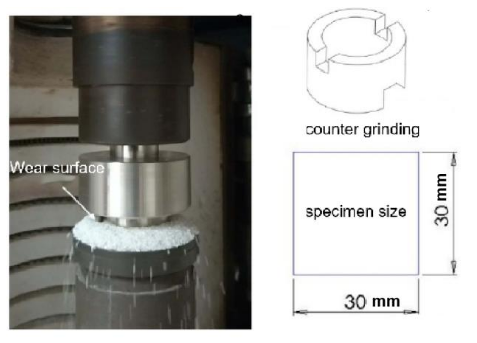
The hardness of the specimen was measured at room and high temperatures. The force selected for the Vickers microhardness measurement (VPro, Shanghai, China) was 200 mN, and the holding time was 10 s. The high temperature hardness tests were conducted in an ARCHIMEDES tester (HRN/T150, Sike, Ruhr, Germany) protected by a high purity argon atmosphere. Before the wear tests, the specimen was cleaned in alcohol. The wear tests were carried out by a high-temperature wear test machine (MMU-5G, SiDa Instruments Co., Ltd., Jinan, China) with a loading force of 1000 N and a rotation speed of 100 r/min. The geometry of the specimen was 30 × 30 mm2 with a thickness of 3–5 mm. We used the stainless steel (1Cr18Ni9Ti) as a counter grinding part. The geometry of the counter part was carefully designed in order to create the three-body wear configurations. The abrasive sand could be leaked continuously from the channel in the center of the rotating shaft, as shown in Figure 1. The specimen was embedded in the sand. The abrasive sand was white corundum with a size of about 0.2 mm, and the flow rate of the abrasive alumina powder was about 50 g/min. The time of the abrasive wear test was 60 min for both room and high temperatures. A 20 min pregrinding process was conducted on each specimen. The mass of specimens before and after the test was measured by a high-resolution balance with a readability of 0.1 mg (METTLER TOLEDO).

3. Results

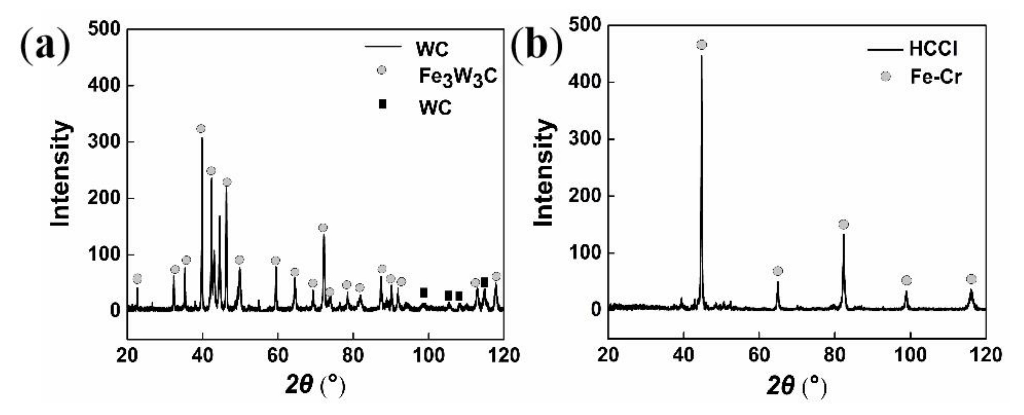
Figure 2 shows the XRD patterns of the WC and HCCI welded layers. It shows that the WC welded layer contains three phases: Fe3W3C, BCC iron, and WC. Contrary to conventional views, the Fe3W3C is the main phase of the WC welded layer, as shown in Figure 2a. The intensity of the diffraction peaks of WC phase is very weak compared to the other two phases. This demonstrates that the WC particle is not stable during the welding process in the present Fe–WC system. On the other hand, the Fe–Cr phase is the dominant phase of the HCCI welded layer, as shown in Figure 2b. The fine peaks in Figure 2b belong to the Cr7C3 and Cr23C6 phases in the HCCI welded layer.
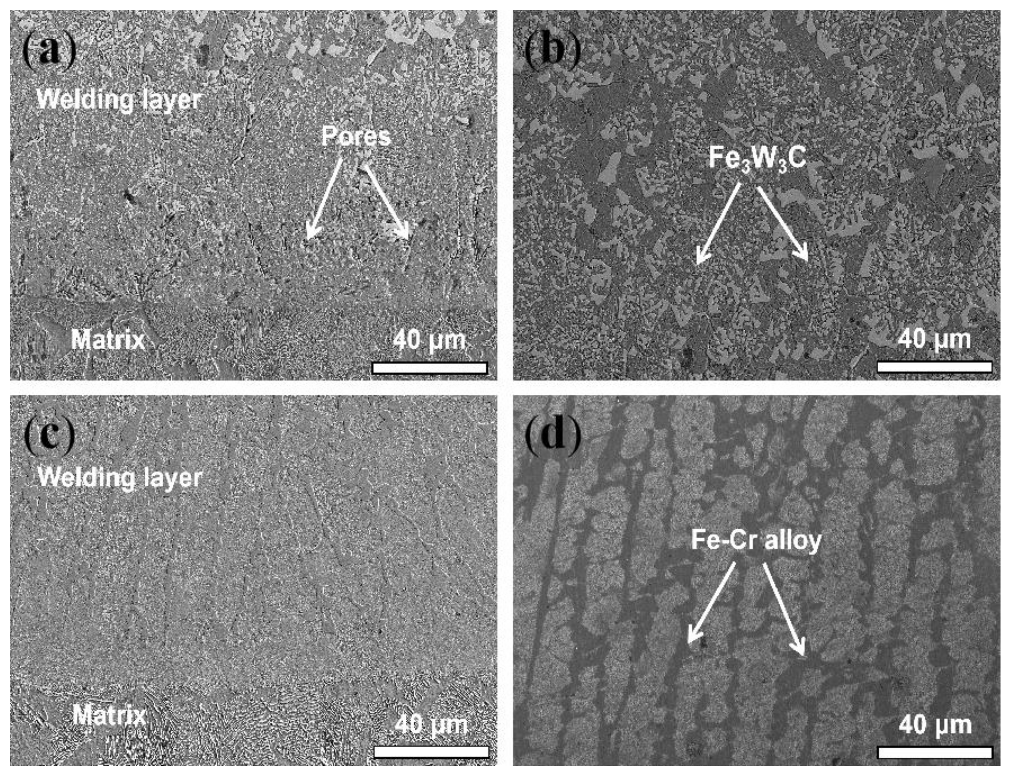
Figure 3 displays the cross-section microstructure of the WC and HCCI welded layers. Both welded layers show good bonding with the matrix since no interfacial cracks were observed in the SEM. Some pores can be found in the interface of the WC welded layer, as shown in Figure 3a, but there is no pore in the interior of the welded layer, as shown in Figure 3b. Higher magnification images show that the microstructure of the WC welded layer contains two categories of particles, and these particles are W-rich, as shown in Figure 3b. Combined with the XRD results, we can conclude that the particles in the WC welded layer are mainly the Fe3W3C phase. For the HCCI welded layer, the microstructure consists of two interconnected phases, as shown in Figure 3d.
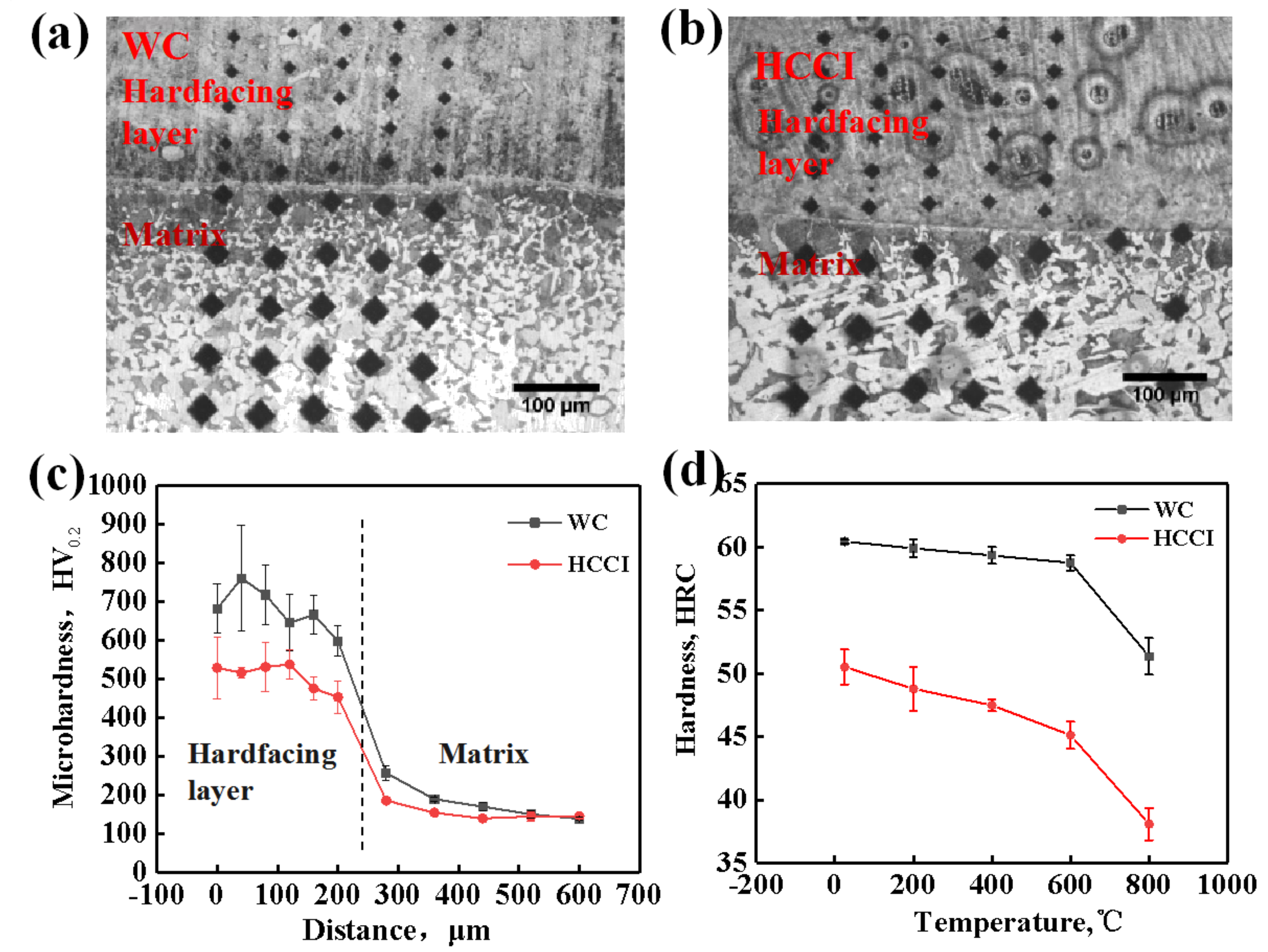
Furthermore, we conducted the Vickers hardness tests to evaluate the hardness changes from the welded layer to the matrix of the WC and HCCI layers. Figure 4a,b show the indentations on the hardfacing layer and matrix. Five tests were conducted for each data point. Figure 4c shows the hardness results. It shows that the hardness of the hardfacing layer is much higher than that of the matrix. Furthermore, the hardness of the WC welded layer is higher than that of the HCCI hardfacing layer in the same distances from the welding interface.
In order to evaluate the high-temperature properties of the hardfacing layers, Figure 4b shows the results of the temperature-dependent hardness tests. It is noted that the hardness of the WC layers is higher than that of the HCCI welded layer at all the temperatures. Meanwhile, the hardness of the WC welded layer just decreases slightly with temperature at temperatures lower than 600 °C, as shown in Figure 4b. The HRC of the WC welded layer at 800 °C is as high as 52 HRC. For comparison, the hardness of the HCCI welded layer decreases quickly with temperature and the hardness becomes as low as 37 HRC at the temperature of 800 °C. This shows that the WC welded layer has a higher hardness than the HCCI welded layer, especially at high temperatures.
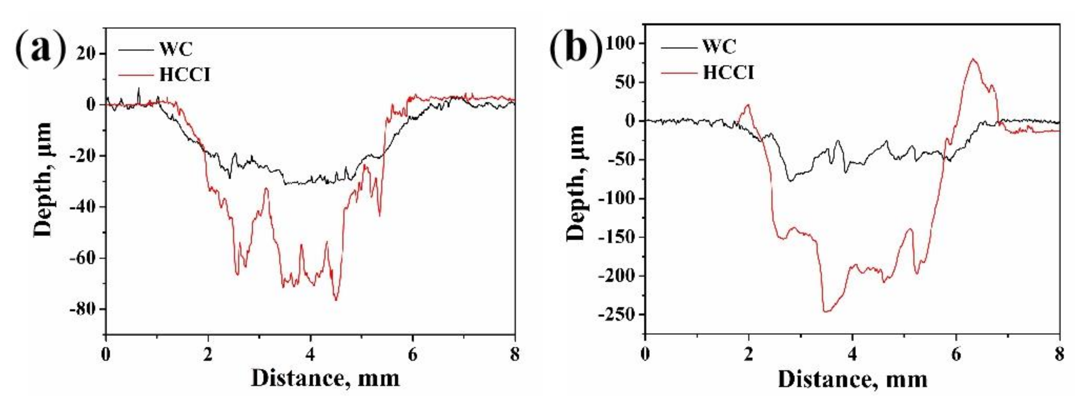
Table 2 shows the abrasive wear properties of the WC and HCCI welded layers at room temperature. Weight loss was used to evaluate wear resistance. It shows that the weight loss of the HCCI layer is about two times that of the WC welded layer. In other words, the wear resistance of the present WC hardfacing layer is twice that of the HCCI hardfacing layer, which is consistent with the hardness test results as shown in Figure 4c. The abrasive properties can be investigated by weight loss at room temperature. However, obvious weight gain can be caused by oxidation at high temperatures. Therefore, we conduct profile analysis on the wear trace on the specimens after an abrasive wear test, as shown in Figure 5. The volume loss of the trace was calculated. Four profiles were used to obtain statistically reliable data. Table 3 shows the volume loss results at room and high temperatures of two welded layers. Wear resistance was reflected by the reciprocal of volume loss. This shows that the wear resistance of the WC welded layer is about twice that of the HCCI layer at room temperature, which is consistent with the results provided in Table 2. However, at 800 °C, the wear resistance of the WC welded layer is three times that of the HCCI welded layer. This demonstrates that the present WC welded layer has excellent wear resistance at high temperatures.
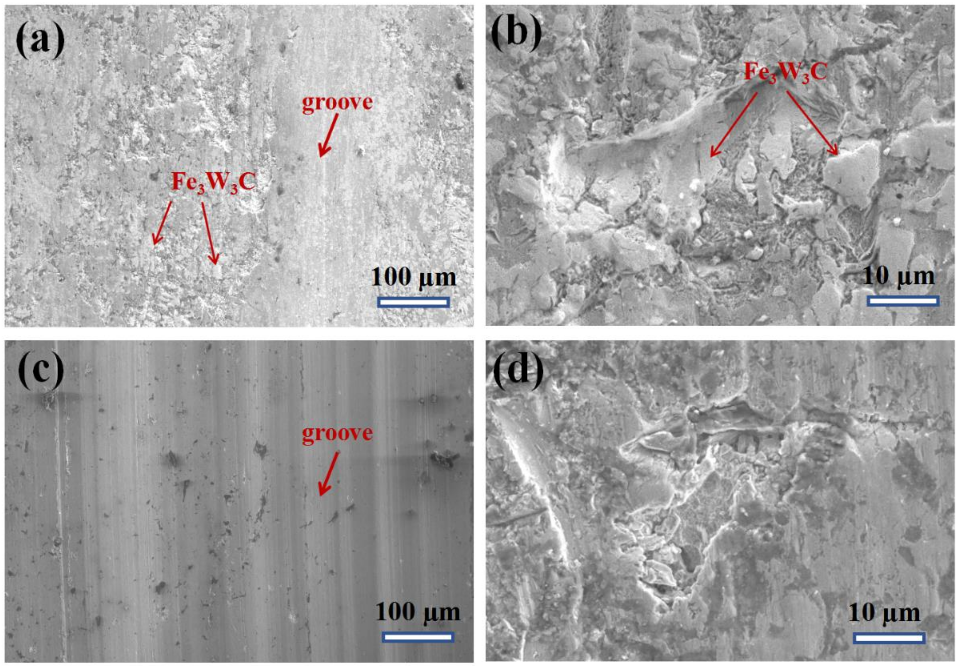
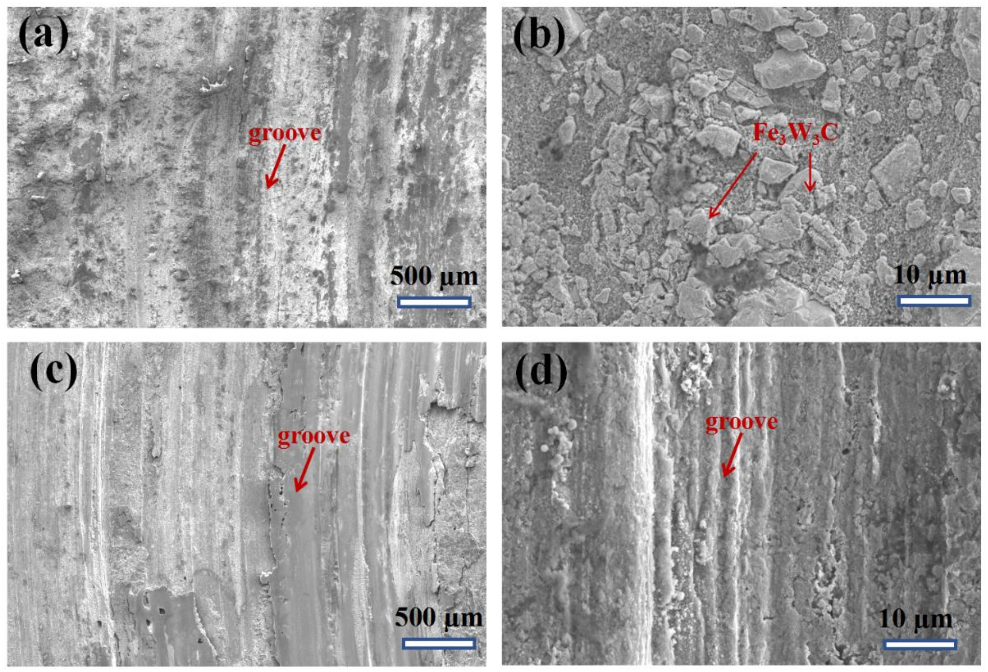
Figure 6 shows the worn surface of the WC welded layer Figure 6a,b and the HCCI welded layer Figure 6c,d. And the cross-section profiles of both the welded layers at room temperature and high temperature. For the WC welded layer at room temperature conditions, Fe3W3C particles can be observed on the worn surface, as shown in Figure 6a. A higher magnification SEM image (Figure 6b) shows that there are no interior and interfacial cracks in the Fe3W3C particles after wear tests. The extrusion of the Fe3W3C particles shows that the presence of these particles can effectively resist wear and hence, improve the wear resistance. For comparison, the worn surface of HCCI at room temperature is very flat and consists of many large grooves. Figure 7 shows the worn surface after abrasive wear tests at 800 °C. Compared with Figure 6, it shows that oxidation takes place obviously at high temperatures, since the worn surface becomes porous, as shown in Figure 7b,d. The oxidation process will accelerate weight loss during the abrasive wear process. Furthermore, some fine grooves were found in the HCCI welded layer, as shown in Figure 7d. This shows that microcutting may be the dominant failure mechanism for the HCCI welded layer at high temperatures. For comparison, obvious particle extrusion was observed on the worn surface of the WC welded layer after abrasive tests at 800 °C, as shown in Figure 7b. This shows that the Fe3W3C particles can also resist wear at high temperatures.

4. Discussion

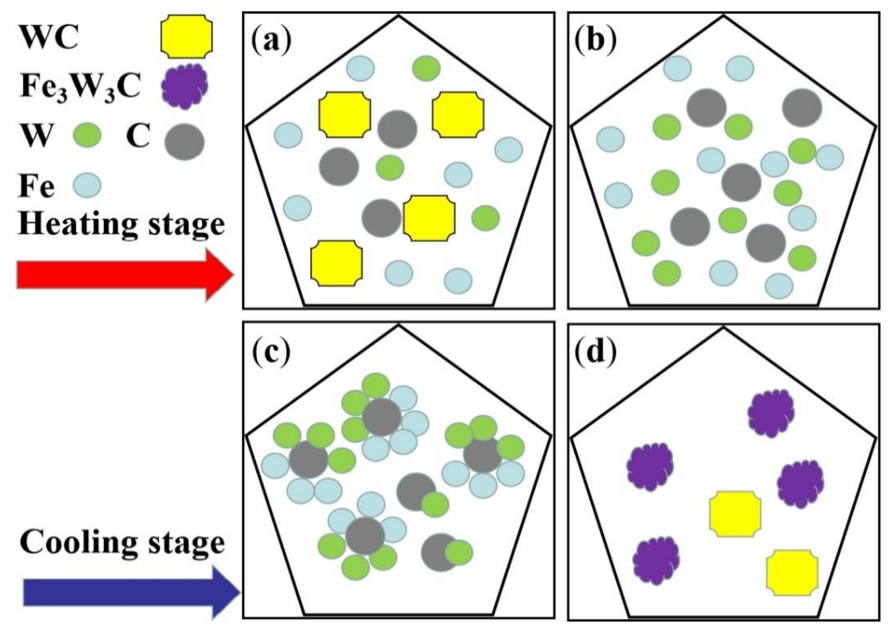
The microstructure, hardness, and abrasive wear properties of the WC and HCCI welded layers were investigated in this work. Contrary to conventional views, we find that the WC welded layer contains a minor WC phase. The Fe3W3C phase is the dominant strengthening particle in the WC welded layer. This shows that the WC particles will decompose during the welding process. Figure 8 is a schematic diagram that shows the formation processes of the Fe3W3C phase. During the welding process, while the temperature reaches a temperature of about 2870 °C, the WC particle begins to melt and the C and W atoms dissolve from the compounds (Figure 8a). As the temperature rises continuously, the molten pool emerges at the highest temperature and long-range diffusion of C, W, and Fe atoms occurs (Figure 8b). During the cooling stage, the Fe3W3C phase is formed firstly due to its low binding energy, as shown in Figure 8c. As the reaction continues, when the localized Fe is consumed by the formations of the Fe3W3C phase, some WC particles are formed, as shown in Figure 8d.
Based on the above results, the excellent wear resistance of the WC welded layer is caused by the formation of Fe3W3C particles. As shown in Figure 3a, it was found that different shapes of Fe3W3C particles are randomly distributed on the surface and the maximum size of Fe3W3C particles is less than 15 μm. On the contrary, although the hard phase can be observed on the surface of the HCCI welded layer, the size of the primary Fe–Cr phase exceeds 50 μm and it is not suitable for wear conditions. Therefore, the fine Fe3W3C particles contribute to the excellent mechanical properties of the WC welded layer. It has been reported that fine and sphere WC particles have a better strengthening effect than that of the irregular WC particles in the Co matrix welded layer, since the presence of a round particle can reduce the residual stress formed during solidification [2]. However, in the present Fe–WC welding system, the introduction of spherical WC particles is not necessary because most of the WC phase will transform to the Fe3W3C phase.
The present experimental results show that the wear resistance of the WC welded layer is better than that of the HCCI welded layer. The difference of wear properties and worn surface of these two welded layers can be due to the different hardness (Figure 4c,d). For the high-temperature abrasive wear tests, oxidation occurs simultaneously; the oxide scale is brittle and can be readily removed during the wear process. Therefore, corrosion and microcutting are the dominant mechanisms for the mass loss of the HCCI welded layer at high temperatures. However, for the WC welded layer, the Fe3W3C particles emerge on the surface and no fracture and pull-out are found. It suggests that Fe3W3C may have high oxidation resistance, thus, contributing to the improved wear resistance at high temperatures.
5. Conclusions

  • The WC and HCCI hardfacing layers were prepared on the Q235 matrix. The welded layers have higher hardness than the matrix.
  • The Fe3W3C is the dominant strengthening phase in the WC welded layer. The hardness of the WC welded layer is HRC 61 and HRC 51 at room temperature and 800 °C, respectively.
  • The abrasive wear resistance of the WC welded layer is better than that of the HCCI welded layer. Specifically, the abrasive wear resistance of the WC welded layer is twice that of the HCCI welded layer at room temperature, and is triple at 800 °C.

Author Contributions

R.J.: manuscript editing and part of the research ideas design; S.L. and Z.L.: to finalize the version to be published; J.N. and H.W.: research acquisition data and data analysis; T.L. and Z.W.: train of thought design and experimental supervision; Y.Z. and X.Y.: editing graphics and text and manuscript writing guidance. All authors have read and agreed to the published version of the manuscript.

Funding

This research was funded by Guangdong Academy of Science (2020GDASYL-20200103134), National Natural Science Foundation of China (51901049), China Postdoctoral Science Foundation (2019M662821), Guangzhou International Science and Technology Cooperation Project (201907010026), Guangdong International Science and Technology Cooperation Project (2018A050506055).

Conflicts of Interest

The authors declare no conflict of interest.

References

  1. Buytoz, S. Microstructural properties of SiC based hardfacing on low alloy steel. Surf. Coat. Technol. 2006, 200, 3734–3742. [Google Scholar] [CrossRef]
  2. Prabanjan, K.S.; Karthick, J.; Rejvin Kumar, S.; Ramkumar, A.; Riswan, A. Wear behavior and metallurgical characteristics of particle reinforced metal matrix composites produced by hardfacing: A review. Mater. Today Proc. 2020, in press. [Google Scholar] [CrossRef]
  3. Nagentrau, M.; Tobi, A.M.; Sambu, M.; Jamian, S. The influence of welding condition on the microstructure of WC hardfacing coating on carbon steel substrate. Int. J. Refract. Met. Hard Mater. 2019, 82, 43–57. [Google Scholar] [CrossRef]
  4. Yang, K.; Gao, Y.; Bao, Y.; Jiang, Y. Microstructure and wear resistance of Fe–Cr13–C–Nb hardfacing alloy with Ti addition. Wear 2017, 376, 1091–1096. [Google Scholar] [CrossRef]
  5. Dilawary, S.A.A.; Motallebzadeh, A.; Atar, E.; Cimenoglu, H. Influence of Mo on the high temperature wear performance of NiCrBSi hardfacings. Tribol. Int. 2018, 127, 288–295. [Google Scholar] [CrossRef]
  6. Pu, J.; Li, Z.; Hu, Q.; Wang, Y. Effect of heat treatment on microstructure and wear resistance of high manganese steel surfacing layer. Int. J. Mod. Phys. B 2019, 33. [Google Scholar] [CrossRef]
  7. Yin, Y.; Pan, C.; Zhang, R.; Zhao, C.; Qu, Y. The effect of Ti addition on the microstructure and properties of high chromium iron-based coatings. J. Alloy. Compd. 2018, 765, 782–790. [Google Scholar] [CrossRef]
  8. Wang, J.; Qi, X.; Xing, X.; Shi, Z.; Zhou, Y.; Yang, Q. Refinement of M7C3 in hypereutectic Fe-based hardfacing coating and interface behavior of (Ti, Nb)(C,N)/M7C3 from first-principles. Mater. Res. Express 2019, 6, 0865h3. [Google Scholar] [CrossRef]
  9. Singh, J.; Thakur, L.; Angra, S. An investigation on the parameter optimization and abrasive wear behaviour of nanostructured WC–10Co–4Cr TIG weld cladding. Surf. Coat. Technol. 2020, 386, 125474. [Google Scholar] [CrossRef]
  10. Yan, X.; Huang, C.; Chen, C.; Bolot, R.; Dembinski, L.; Huang, R.; Ma, W.; Liao, H.; Liu, M. Additive manufacturing of WC reinforced maraging steel 300 composites by cold spraying and selective laser melting. Surf. Coat. Technol. 2019, 371, 161–171. [Google Scholar] [CrossRef]
  11. Zhang, H.; Li, H.; Yan, L.; Wang, C.; Ai, F.; Li, Y.; Li, N.; Jiang, Z. Effect of Particle Size on Microstructure and Element Diffusion at the Interface of Tungsten Carbide/High Strength Steel Composites. Materials 2019, 12, 4164. [Google Scholar] [CrossRef] [PubMed] [Green Version]
Figure 1. The high-temperature three-body abrasive wear-resistant setup and the geometries of specimen.
Coatings 10 00852 g001
Figure 2. The XRD patterns of the WC welded layer (a) and HCCI welded layer (b).
Coatings 10 00852 g002
Figure 3. The SEM image of the cross-section of the welded layers: (a,b) WC welded layer; (c,d) HCCI welded layer.
Coatings 10 00852 g003
Figure 4. The hardness of the welded layer at room and high temperatures: (a,b) the indentations on the WC and HCCI hardfacing layers; (c) the Vickers hardness changes from the welded layer to the matrix; (d) the high temperature HRC hardness of both the welded layers.
Coatings 10 00852 g004
Figure 5. Profile of abrasive wear traces at room temperature (a) and 800 °C (b).
Coatings 10 00852 g005
Figure 6. The worn surface after abrasive wear test at room temperature: (a,b) WC welded layer. (c,d) HCCI welded layer.
Coatings 10 00852 g006
Figure 7. The worn surface after abrasive wear test at 800 °C: (a,b) WC welded layer. (c,d) HCCI welded layer.
Coatings 10 00852 g007
Figure 8. Schematic diagram showing the formation process of the Fe3W3C phase: (a) the dissolution of WC, (b) the diffusion of W, C, and Fe atoms in liquid, (c) formation of Fe3W3C, and (d) the formation of WC.
Coatings 10 00852 g008
Table 1. The main compositions of welding rods.
Welding RodMain ElementWeight Percent (%)
WCC1.5–3.0
W40–50
Fe10–20
HCCIC2.0–3.5
Cr16–20
B1–2
Fe40–50
Table 2. Abrasive wear weight loss at room temperature.
SampleWeight Loss
Δm (g)
Standard Deviation (g)Wear Resistance (1/Δm, 1/g)
1#0.08900.013511.23
2#0.16090.02316.21
Table 3. Volume loss of abrasive wear at room and high temperatures.
SampleVolume Loss ΔV (mm3)Standard Deviation (mm3)Wear Resistance (1/ΔV, 1/mm3)
WC-RT7.220.660.139
HCCI-RT14.131.840.071
WC-800 °C13.010.750.077
HCCI-800 °C37.83120.026