Article

Coating Process Parameters and Structural Properties of the Tubular Electrodes of Fuel Cells Based on a Self-Made Coating Device

1
School of Mechanical Engineering, Nantong University, Nantong 226019, China
2
Faculty of Engineering, Tokushima University, Tokushima 770-8506, Japan
3
Shanghai Key Laboratory for High Temperature Materials and Precision Forming, Shanghai Jiao Tong University, Shanghai 200240, China
*
Authors to whom correspondence should be addressed.
Coatings 2020, 10(9), 830; https://doi.org/10.3390/coatings10090830
Submission received: 11 August 2020 / Revised: 22 August 2020 / Accepted: 26 August 2020 / Published: 27 August 2020
(This article belongs to the Special Issue Thin Films and Coatings for Energy Application)

Abstract

:
The electrode is one of the most important components of tubular direct methanol fuel cells (DMFC), and the coating process directly determines its performance. In the present research, a tubular electrode coating device was designed based on planetary gear structures, and the influence of the coating process parameters on the electrode structure’s performance was studied. The experimental results show that: the coating layer on the electrode surface prepared by the self-made device is uniform and dense, and the coating surface quality is better than a manual coating. The best coating environment temperature is 30–40 °C, and the coating spindle speed is 6.67 r/min. Under the condition in which Nafion 117 is used as the proton exchange membrane, the fuel cell is placed in 1 mol/L H2SO4 + 0.5 mol/L CH3OH electrolyte, and high-purity oxygen is fed at a rate of 100 mL/min, the power density of the electrode coated by the self-made device can reach 20.50 mW/cm2, which is about 2.4 times that of the electrode coated manually.

1. Introduction

Energy is the basis for the survival and development of human society. It not only provides impetus for economic development, but also determines the life quality of people. However, with the consumption of nonrenewable energy sources, such as oil, coal and natural gas, serious environmental problems have emerged worldwide [1,2,3]. As a new type of energy source, fuel cells can directly convert the chemical energy existing in fuel and oxidants into electrical energy [4]. They have the advantages of a high energy conversion efficiency and low pollution. Thus, fuel cells are widely used across the globe.
The tubular direct methanol fuel cell (DMFC) is a kind of fuel cell, and it directly uses methanol aqueous solution or steam methanol as the fuel supply source [5,6]. DMFCs have the characteristics of a fast start at low temperatures, they are clean and protect the environment, and have simple battery structures, which makes DMFCs likely to become mainstream portable electronic products in the future [7,8]. Membrane electrode assembly (MEA) is a combination of the proton exchange membranes (PEMs), catalysts and electrodes of fuel cells [9]. Among them, the electrode is divided into an anode and a cathode, which are hot pressed on PEMs [10]. The performance of the electrode directly determines the performance of the DMFC, so how to prepare the electrode and improve its structural properties has become a research focus [11]. The special-shaped structure of the DMFC uses nonplanar electrodes or does not use bipolar plates with complex flow fields, which not only reduces the processing difficulty and electrode weight, but also solves the fuel filling and storage problems. Common DMFC electrodes with special-shaped structures include tubular, V-shaped and U-shaped structures. Among them, the tubular electrode has a more thorough chemical reaction, which has attracted more attention from researchers.
Coating is a solid continuous film achieved by applying paint, which can be used in anticorrosion materials [12], additive manufacturing and other fields. Common spraying methods include manual spraying, machine spraying, plasma spraying [13,14], etc. Currently, the production of the diffusion layer and the catalytic layer on the surface of the tubular DMFC electrode is still at the stage of manual coating. In order to meet a certain loading capacity, the electrode is often repeatedly coated dozens of times. Such repeated operations have high requirements on the patience of the experimenters and the slurry used for coating. Moreover, the electrode surface obtained by manual coating has poor uniformity and the coating layer is easy to crack. Therefore, a convenient and fast coating device is needed to replace manual coating. The device should maintain a good bonding state between the diffusion layer and the catalytic layer to ensure a high accuracy. In order to promote the industrialization of tubular DMFCs, it is of great significance to develop a tubular electrode coating device that can improve the production efficiency of tubular DMFCs and replace manual repetitive labor.
At present, a few scholars have carried out relevant research on tubular electrode coating devices and coating parameters. The gears are not only used for power transmission [15], but also for designing electrode coating devices. Hongjun Ni [16] and other scholars designed a direct methanol fuel cell cathode coating device based on planetary gears, which can simultaneously coat multiple electrodes while ensuring the coating quality. Hee Jeong Shin et al. [17] proposed a centrifugal coating method that uses a centrifugal device to perform coating with a very low concentration of silver nanowire (Ag NW) solution to produce Ag NW electrodes without post-processing. The coating method used in this study was spin coating. O. Mellbring et al. [18] studied the spin-coating and characterization of high-density polyethylene films and found that the initial deposition temperature was the main parameter affecting the performance of the spin-coated film. Stéphane Fierro et al. [19] manufactured the IrO2 electrode using spin coating deposition technology, which can obtain a thin and uniform IrO2 coating under a controlled load. W. Haselrieder et al. [20] studied the structure of the electrode coating and proposed a method for measuring the adhesion strength of the coating of the lithium ion battery electrode. It has been proved that the data acquisition rate, contact stress, dwell time and pull-off velocity have a significant effect on the measurement of the bonding strength of the electrode coating.
In this article, the tubular electrode of the DMFC is taken as the research object. The tubular electrode is prepared using a self-made coating device, and the optimal coating parameters are determined. Then, the tubular electrode prepared under the optimal coating process was used for a structure properties analysis and power generation experiments to verify the feasibility of the experimental schemes.

2. Materials and Equipment

2.1. Main Raw Materials and Equipment

The main raw materials and reagents of the experiment are shown in Table 1.
The coating slurry was stirred evenly through the constant temperature multihead magnetic stirrer, namely the HJ-6A type, produced by Jintan Ronghua Instrument Manufacturing Co., Ltd. (Changzhou, Jiangsu, China). The electrochemical performance of the DMFC was tested by ean lectrochemical workstation, which was the CHI660C type produced by Shanghai Huachen Instrument Company (Shanghai, China). The polytetrafluoroethylene (PTFE) in the cathode diffusion layer was completely carbonized through the tube resistance furnace, the SSK2-2-10 type, which was produced by Shanghai Yifeng Electric Furnace Co., Ltd. (Shanghai, China). The electrode microstructure was observed through a scanning electron microscope, the S-3400N type, produced by Hitachi, Ltd. (Tokyo, Japan). Finally, we used a laboratory-made tubular electrode preparation device to coat the electrodes.
In the process of studying the influence of parameters, electrolyte, oxidant, and the proton exchange membrane were selected as the main research variables. The electrolyte was divided into 1 mol/L H2SO4 + 0.5 mol/L CH3OH solution and 0.5 mol/L H2SO4 + 2 mol/L CH3OH solution. Oxygen as the oxidant was introduced into the electrode at flow rates of 20 mL/min, 40 mL/min, 60 mL/min, 80 mL/min and 100 mL/min. Nafion 117, Nafion 115 and Nafion 212 were used as proton exchange membranes to investigate the performance of the DMFC. When evaluating the performance of the prepared electrode, the denser the coating structure, the more durable the prepared electrode. The higher the power density and initial potential, the faster the chemical reaction and the faster the rate of electricity generation. During the experiment, the simulation results can be obtained directly, while the test results need to be averaged through multiple measurements.

2.2. Coating Device

2.2.1. The Structure of the Tubular Electrode

Figure 1 shows a complete tubular electrode of the DMFC, where the numbers 1 to 6 represent the proton exchange membrane, the cathode catalyst layer, the cathode diffusion layer, the cathode support, the anode catalyst layer and the anode support, respectively. The support is made of the mesophase carbon microsphere graphite ball (MCMB/G) tube or porous graphite tube, the diffusion layer was obtained by mixing carbon powder and PTFE emulsion, and the catalytic layer was prepared by mixing Pt/C catalyst and Nafion solution.

2.2.2. Design of the Coating Device

The coating device used in our experiment was self-made in the laboratory, as shown in Figure 2. The coating device was designed based on the structure of the planetary gear system [21,22]. The planetary gear system included one sun gear and three planetary gears. The main shaft was connected to the motor to drive the sun gear on the shaft, and then the planetary gear matched with the sun gear was rotated. The electrode was installed on a support frame, and the support frame was fixed on the central axis of the planetary gear. The electrode revolved around the main axis and rotated around the centerline of the planetary gear. The length of the bent part of the electrode support frame was longer than the radius of the addendum circle of the planetary gear to ensure that the electrode was completely immersed in the slurry box. A dryer was installed next to the slurry box, which can achieve the effect of drying while coating, thereby reducing the degree of deformation of the coating layer.
The electrode was sequentially coated in the slurry box under the action of the planetary gear system. By controlling the heating time of the dryer and the rotation speed of the electrode, the drying could be completed at the same time as the electrode coating, and the time required for electrode preparation could be shortened. It could also be filled with a protective gas such as nitrogen to ensure the drying effect. With the method of double rotary coating, the electrode could be automatically coated without contact, and the coating uniformity was excellent. Secondly, the coating and the drying process were combined to realize the rapid preparation and high quality.

2.2.3. Transmission of the Coating Device

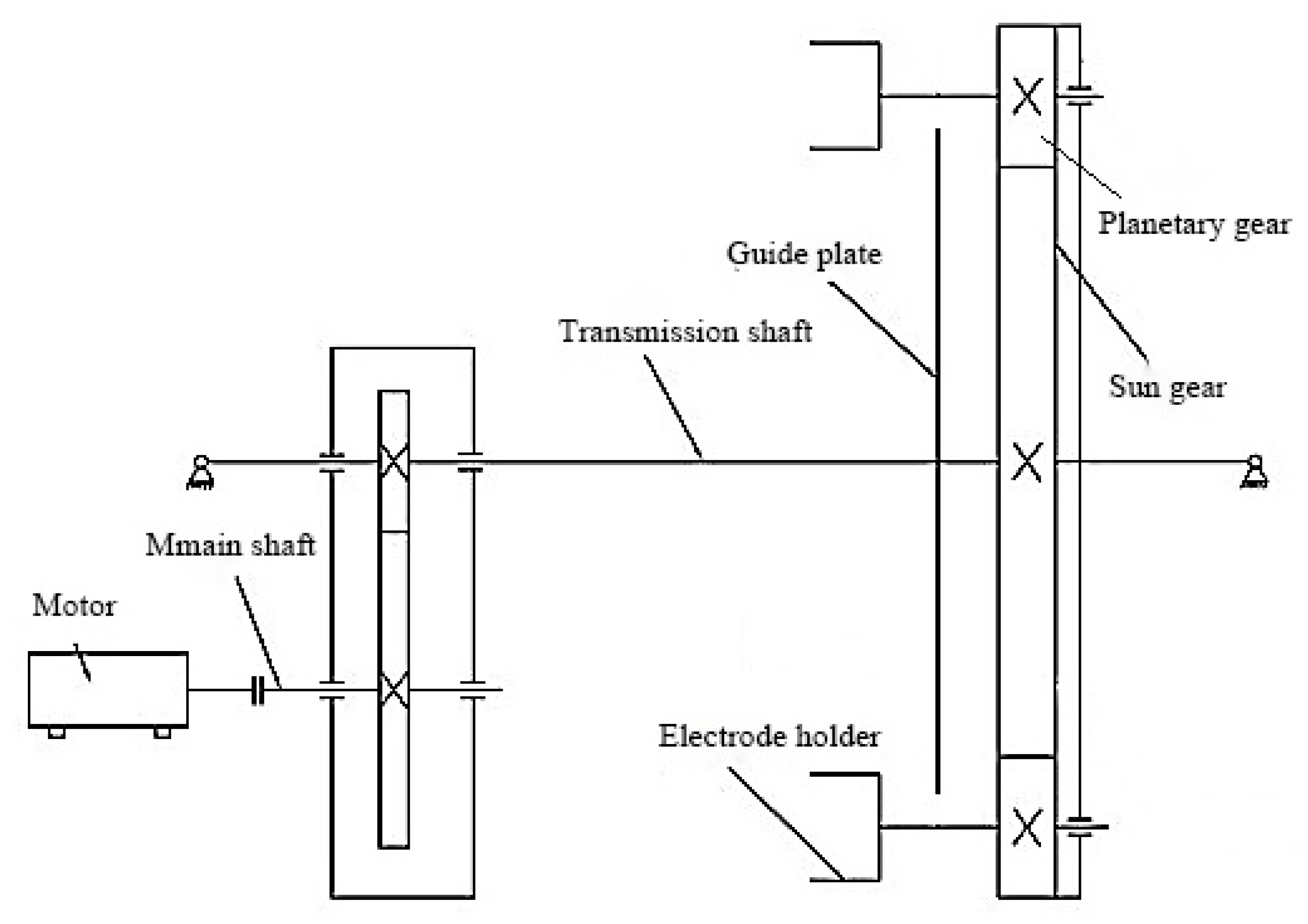
According to the characteristics of the coating method, the gear was selected as the main transmission element, and the transmission mechanism is shown in Figure 3. The main shaft rotated under the drive of the motor, and the gear pair transmitted the movement to the transmission shaft, thereby driving the sun gear and the planetary gear to rotate. The electrode holder was installed in the center of the planetary gear and rotated with the planetary gear. In order to ensure that the inner hole of the tubular electrode was not splashed by the coating slurry, the electrode support was penetrated on the electrode holder. The fit between the electrode support and the electrode holder was a transition fit or interference fit. The electrode did not detach from the electrode holder when the transmission shaft rotated at a low speed. The guide plate could prevent the planetary gear from generating large displacements and reduce the uncertain factors in the movement.

3. Experiments and Results

3.1. Optimization of the Coating Process Parameters

3.1.1. Temperature of Electrode Coating

The coating quality was improved by changing the coating method and environment in our experiment [23,24]. During the coating process, the temperature was kept constant, and the drying speed of the slurry on the outside of the substrate was accelerated, so that the thermal deformation of the single-layer coating slurry was minimized, thereby reducing the deformation of the entire coating and reducing the amount of flaking. However, because the electrode coating was too thin, the deformation was not easy to measure, so a finite element analysis was used to simulate the thermal deformation of the coating.
During the coating process, the deformation generated by the support and coating layer was analyzed by the direct coupling methods [25]. The diffusion layer is made of Vulcan XC-72R carbon powder and 60 wt.% PTFE emulsion in an appropriate ratio. The catalytic layer was prepared by a Pt/C (40 wt.% Pt) catalyst and 5 wt.% Nafion emulsion according to the mass ratio Pt/C: Nafion = 3:1.
During the coating process, a graphite tube with an outer diameter of 6 mm and an inner diameter of 3 mm (purity of 99.99%) was used as the electrode support [26], and then the electrode layer and proton exchange membrane layer were coated on the outside of the graphite tube. These three materials have different elastic moduli and thermal expansion coefficients. Initially, the same temperature of 0 °C was set. The support was fixed internally and deformed by thermal stress, causing the electrode layer and proton exchange membrane layer to fall off. The performance parameters of the three materials are shown in Table 2.
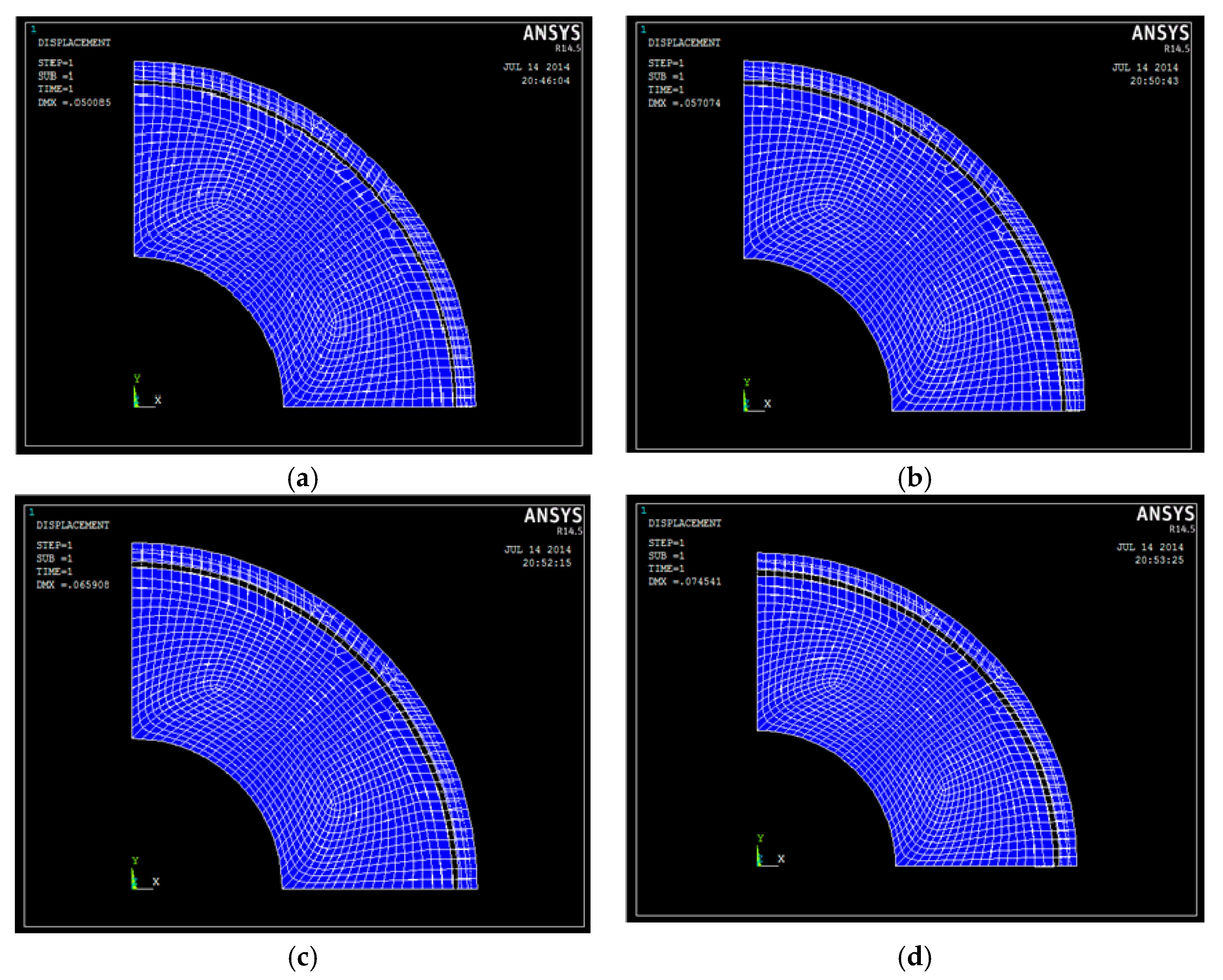
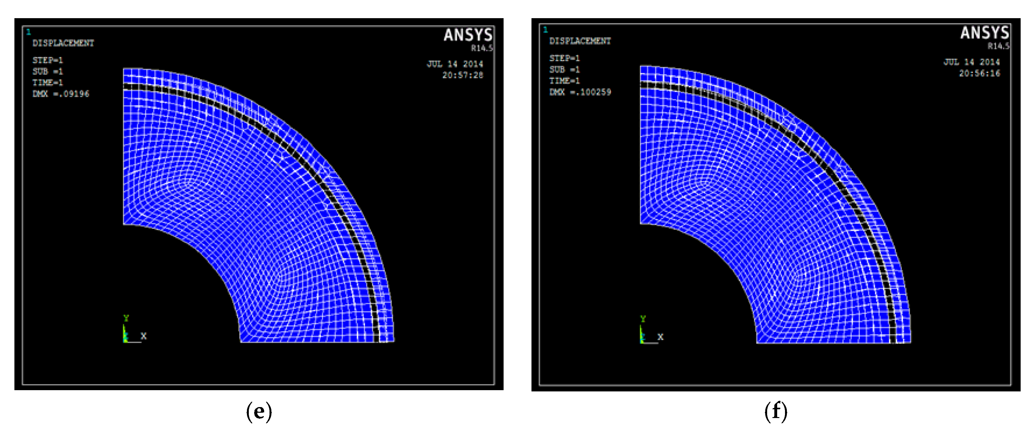
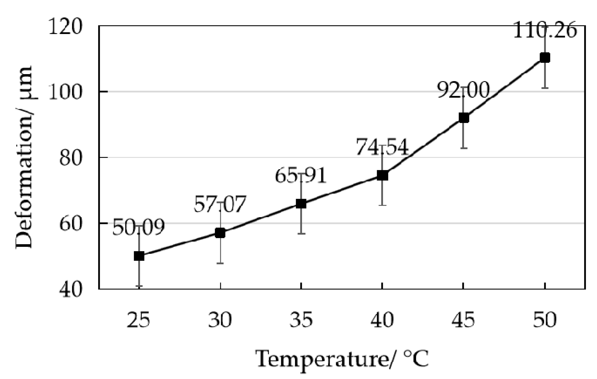
The Ansys software was used to conduct a thermal analysis on the electrode [27,28], and different boundary conditions for the structure and thermal stress were defined, respectively. Since the cross section of the tubular electrode is a centrally symmetrical figure, a quarter of the circle was selected as the simulation object. The horizontal direction is defined as the X-axis, and the vertical direction is defined as the Y-axis. First, the boundary conditions of structural stress were defined. The minimum value of x is 0 and the maximum value is 1.5, the minimum value of y is 0 and the maximum value is 1.5, and fixed constraints in the X and Y directions were applied. Then the boundary conditions of the thermal stress were defined, the minimum value of x is 0, the maximum value is 3.383, the minimum value of y is 0, the maximum value is 3.383, and temperature constraints were imposed at 25, 30, 35, 40, 45 and 50 °C. The stress convergence condition was set to “Default Nonlinear Convergence Criteria”, the minimum reference value was set to 0.001, and then the model was solved to obtain the deformation of the electrode at different temperatures [29], as shown in Figure 4. The deformation results of the electrode at different temperatures were counted, and the graph in Figure 5 is obtained. It can be seen that part of the electrode layer and proton exchange membrane on the outside of the support deforms and peels off to varying degrees as the external temperature increases. The overall trend is that as the temperature increases, the amount of deformation becomes larger.
From Figure 5, we can see that the deformation of the coating layer is relatively slow at 25–40 °C, and the deformation after 40 °C changes abruptly. Besides, the general use temperature of the PTFE emulsion in the diffusion layer composition is 40–50 °C, so a temperature of 40 °C was chosen as the most suitable coating temperature. During the coating process, the temperature can be controlled at 30–40 °C.

3.1.2. Speed of Electrode Coating

A speed-regulated motor was used in our experiment, and a better coating speed could be selected to ensure the quality of the electrode and the coating efficiency [30]. First, the motor speed controller was calibrated, and the speeds of 6.67 r/min and 10 r/min were selected as the better coating speed. Meanwhile, the room temperature was controlled at 40 °C during the experiment. Then, we ran the device for the diffusion layer coating and weighed the electrode every two hours. The statistical results are shown in Figure 6. In the calculation process, we subtracted the initial electrode weight from the coated electrode weight to get the weight gain, and then divided the weight gain by the time to get the average weight gain per hour. To show the uncertainty estimate of the average, we calculated the standard deviation of each set of experimental data. Since we measured the data every two hours, in the process of calculating the standard deviation, we used one-half of the data of each measurement to represent the one-hour weight gain. The calculation results are shown in Table 3.
From Figure 6 we can see that the initial weight of the electrodes is not the same, which is caused by the difference in the manufacturing process. However, this will not have any effect on our experiment, because the datum we need is the increase in the coating weight. In the calculation, the initial weight was subtracted.
It can be calculated from Table 3 that when the coating speed is 6.67 r/min and 10 r/min, the average weight gain of the electrode is 3.05 ± 1.27 mg and 2.22 ± 1.31 mg, respectively. Compared with the speed of 10 r/min, the electrode coating is thicker and heavier with a coating speed of 6.67 r/min. Therefore, the speed of 6.67 r/min was chosen as the better coating speed.
The choice of coating speed is related to the motor. Currently, the adjustable speed of the motor equipped with the coating device is limited. However, through our two sets of comparative experiments we can find the relationship between the coating performance and coating speed. That is, the slower the coating speed, the more the weight of the coating increases, and the thicker the coating. However, in order to ensure the efficiency of the coating, the coating speed should not be too low, so 6.67 r/min is reasonable. In future work, we will further consider increasing the comparative experiment of different coating speeds.
From Figure 6b (6.67 r/min) and Figure 6c (10 r/min), we can see that the weight of the coating has a large jump. This may be due to the presence of large particles in the slurry, which adhere to the electrode surface during the coating process, causing a sudden change in weight. As a gross error, it was directly removed during calculation. Taking Figure 6c (10 r/min) as an example, during the 16–18 h period, the weight of the electrode has a sudden change. Therefore, when calculating the average weight gain of the electrode, the data in this time period were removed and the data in the previous 16 h were kept.

3.2. Research on the Electrode Structure Performance

3.2.1. Experimental Process

After the optimal coating process parameters were determined, the self-made device was used to prepare tubular electrode coatings. The preparation process of electrode coating [31] is shown in Figure 7.
The first step is to pre-process the material, by immersing the electrode support in a 30% nitric acid solution for 2 to 3 h, then taking it out and performing multiple ultrasonic vibrations. The Nafion membrane with suitable size was placed in ultrapure water and sonicated for 1 h, then taken out and put into a 3–5 wt.% H2O2 aqueous solution at 80 °C for 1 h. After removing the organic matter on the surface, it was washed with ultrapure water three times, and put in 80 °C ultrapure water for 1 h. Then, the membrane was placed in a 0.5 mol/L H2SO4 solution at 80 °C for 1 h to remove surface metal ions and washed with ultrapure water three times. Finally, the obtained H+ membrane was immersed in 80 °C ultrapure water three times for 30 min each time. After preparation, the membrane was placed in normal-temperature ultrapure water for use.
In the process of electrode coating, the Vulcan XC-72R carbon powder and 60 wt.% PTFE emulsion were formulated into a diffusion layer slurry in an appropriate ratio, and the slurry was placed in a special slurry box. The electrode support was mounted on the planetary gear and was coated at a temperature of 30 to 40 °C at a speed of 6.67 r/min until it met the weight requirements. In order to ensure that the PTFE in the diffusion layer was completely carbonized, the support that meets the weight requirements of the diffusion layer was placed in a tube resistance furnace. Then, the nitrogen was introduced, sintered at 340 °C for 30 min, and cooled with the furnace.
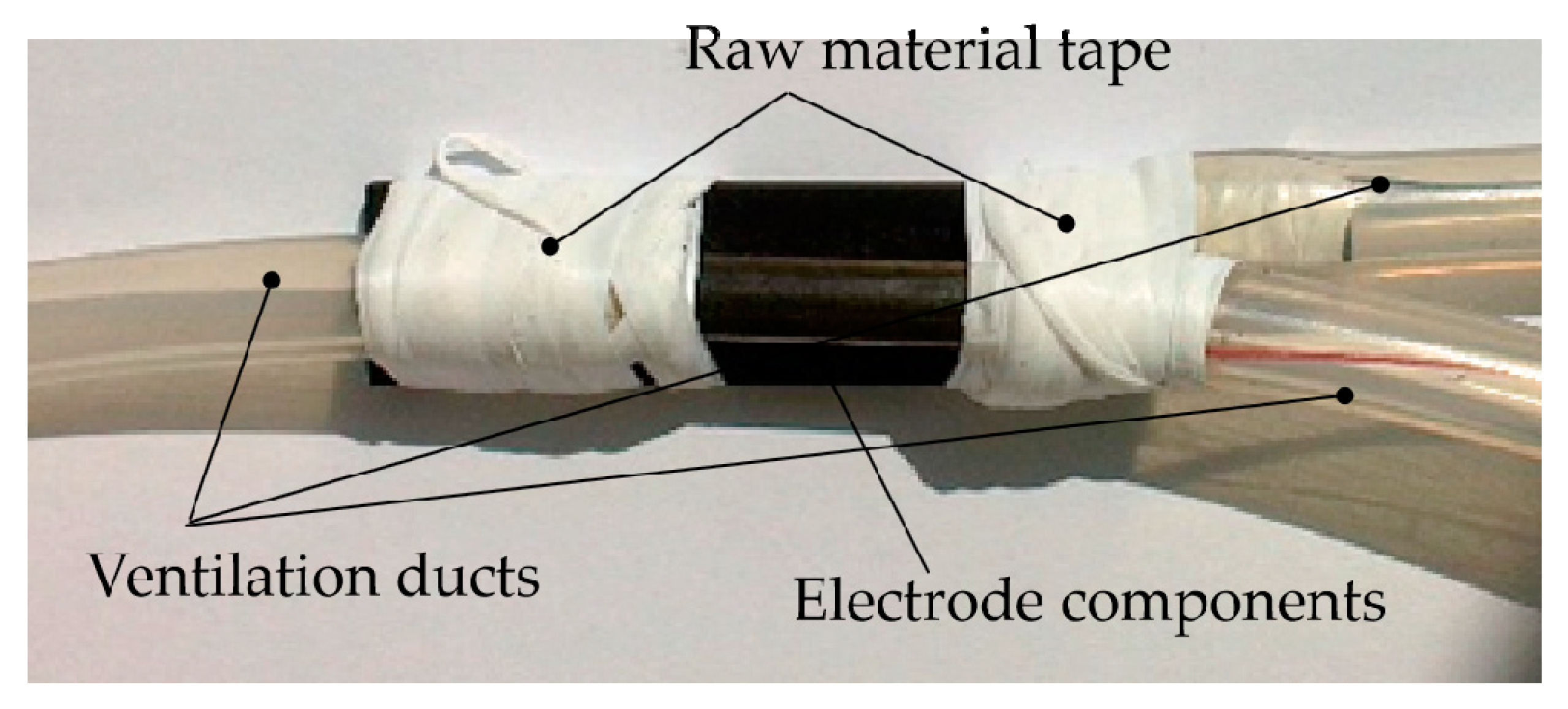
Finally, the prepared electrode was assembled in the DMFC. The hot-pressed method was used to wrap the treated Nafion membrane on the outside of the tubular cathode [32]. The two ends were equipped with ventilation ducts. The raw material tape was used to bind the cathode and the anode to ensure that the DMFC will not loosen during power generation [33]. The structure is shown in Figure 8. After that, the polarization curve of DMFC was measured by using an electrochemical workstation.

3.2.2. The Influence of Experimental Parameters on the Coating Performance

The topography and the electrochemical performance of the electrode were used as the main criteria to judge the quality of the coating. In order to ensure the power generation performance of the electrode, it is necessary to select the experimental parameters. Taking the electrode coated manually as the comparative research object, the experiment was conducted with variables of electrolyte, oxidant (oxygen) and proton exchange membrane.
(1)
Effect of the Electrolyte
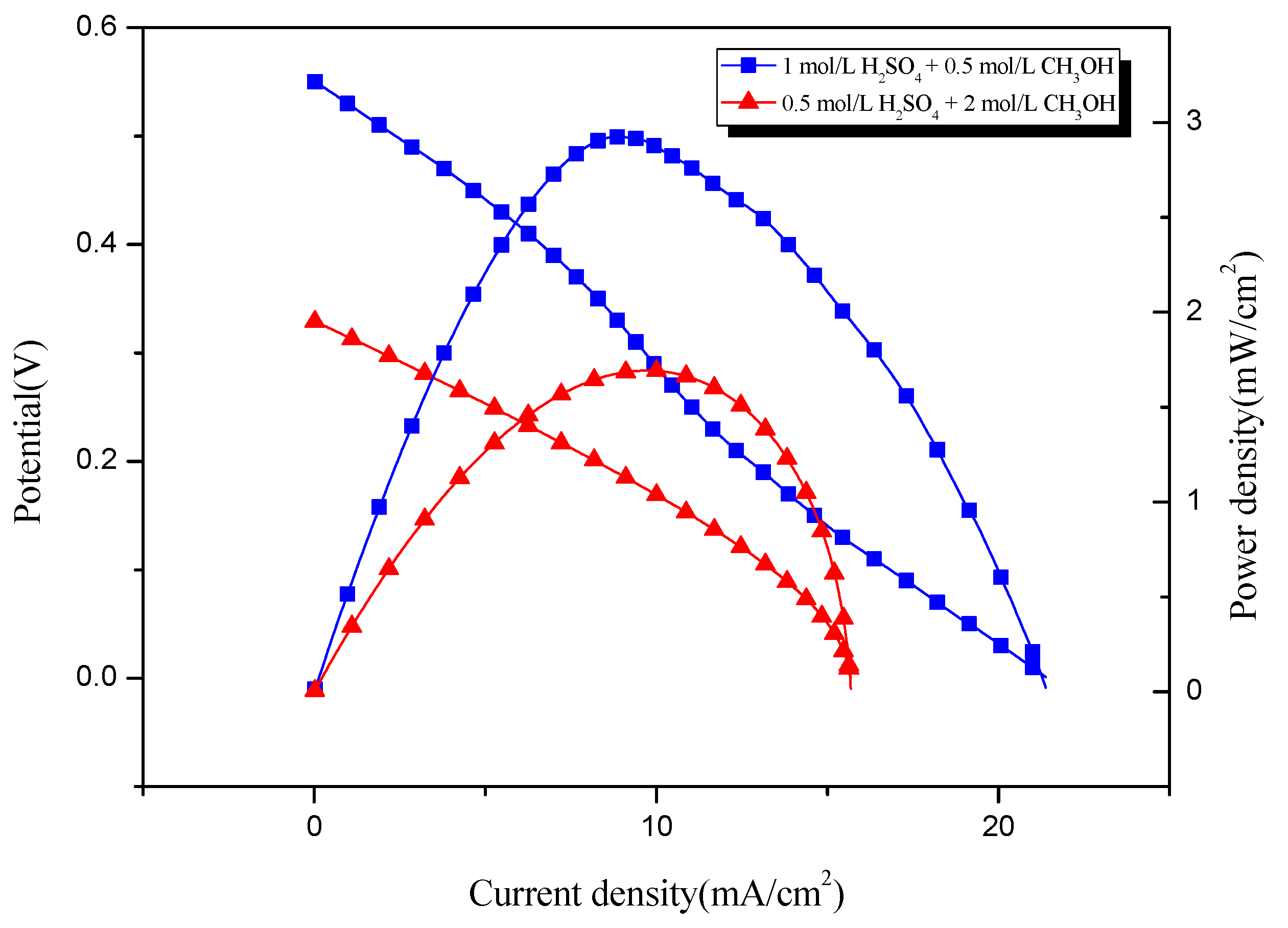
The concentration of methanol directly determines the output performance of the DMFC [34]. The DMFC was put in 1 mol/L H2SO4 + 0.5 mol/L CH3OH solution and 0.5 mol/L H2SO4 + 2 mol/L CH3OH solution for power generation experiments. The performance of the DMFC is shown in Figure 9. In the figure, the curve that gradually decreases as the current density increases is the electric potential curve, and the curve that first increases and then decreases as the current density increases is the power density curve. This phenomenon is applicable to other polarization graphs. From Figure 9, we can see that when the electrolyte is a solution of 1 mol/L H2SO4 + 0.5 mol/L CH3OH, the power density of the DMFC is higher.
(2)
Effect of Oxidants
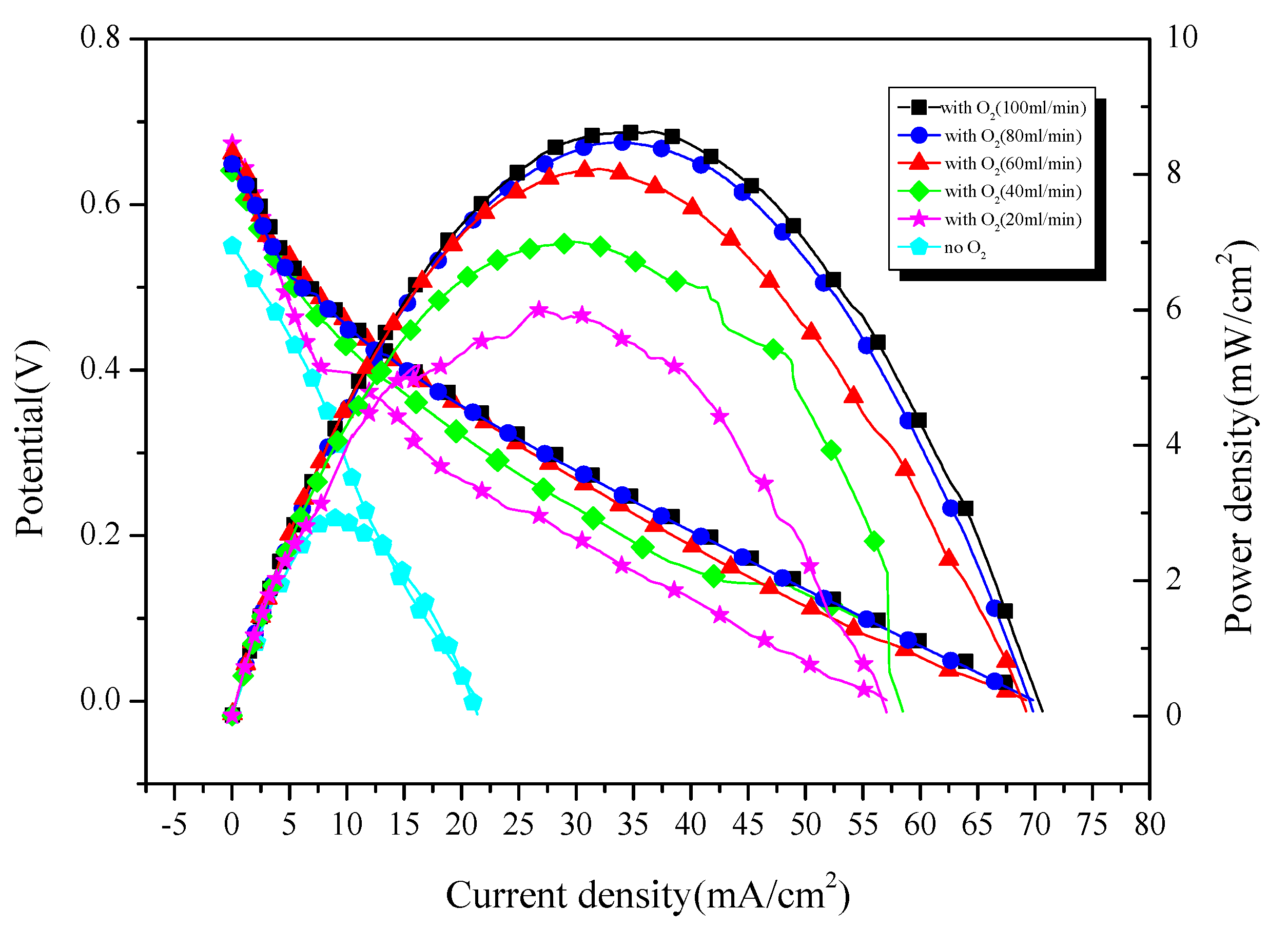
As an important oxidant, oxygen plays an important role in the process of DMFC reactions [35]. When oxygen is introduced into the cathode, the concentration and pressure of oxygen in the cathode tube will increase, so that the mass transfer rate of oxygen in the cathode increases, thereby promoting the cathode electrochemical reaction. The electrochemical performance of the DMFC without oxygen and with oxygen flow rates of 20 mL/min, 40 mL/min, 60 mL/min, 80 mL/min, and 100 mL/min were investigated. The measured polarization curve of the DMFC is shown in Figure 10. When high-purity oxygen was introduced as an oxidant at a rate of 100 mL/min, the power density of the DMFC was higher.
(3)
Effect of PEMs
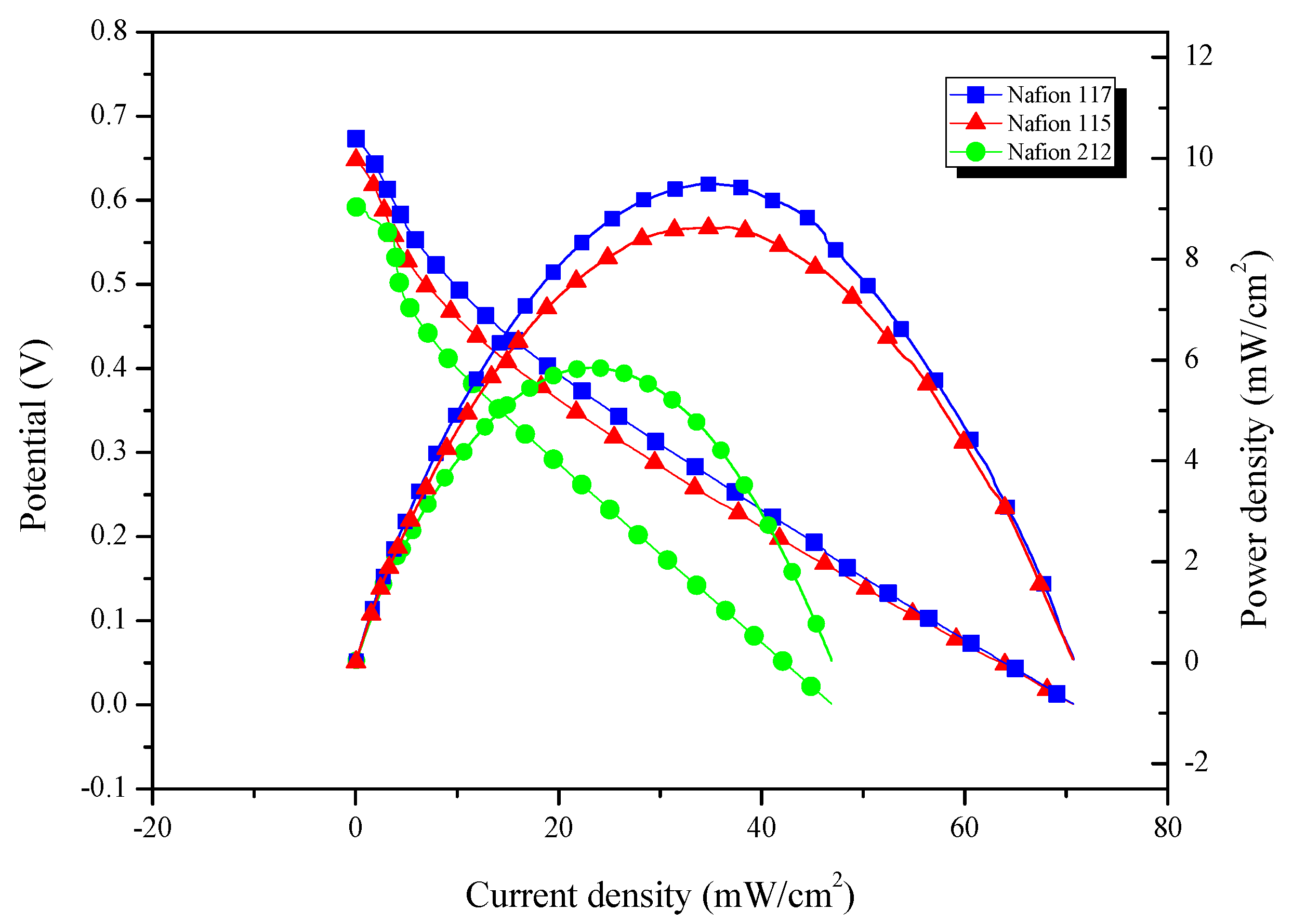
Proton exchange membranes are important components of fuel cells. The thickness of the membrane not only affects the proton passage rate and methanol permeability, but also affects the state of water in the entire reaction [36]. Too-thin or too-thick membranes are detrimental to the reaction. The performance of the DMFC when Nafion 117, Nafion 115 and Nafion 212 were used as PEMs was investigated, respectively. The polarization curve is shown in Figure 11. When the current density is 0, the potential (U0) of Nafion 117 is at its highest. The U0 value reflects the exchange current density of the oxygen reduction reaction. The exchange current density of the oxygen reduction reaction is directly proportional to the oxygen concentration, proton concentration and transfer coefficient of the electrode reaction. Therefore, as the U0 gets larger, the cross-permeation amount of hydrogen and oxygen increases, thereby increasing the rate of the chemical catalytic reaction between the surface of the catalyst and oxygen. Secondly, when Nafion 117 is used as the proton exchange membrane, the power density of the DMFC at its highest, indicating that the energy transmission rate of Nafion 117 is faster.
The experiments show that in order to make DMFC exhibit a good electrochemical performance, the selection of the parameters in our experiment is shown in Table 4.

3.2.3. Analysis of Coating Morphology

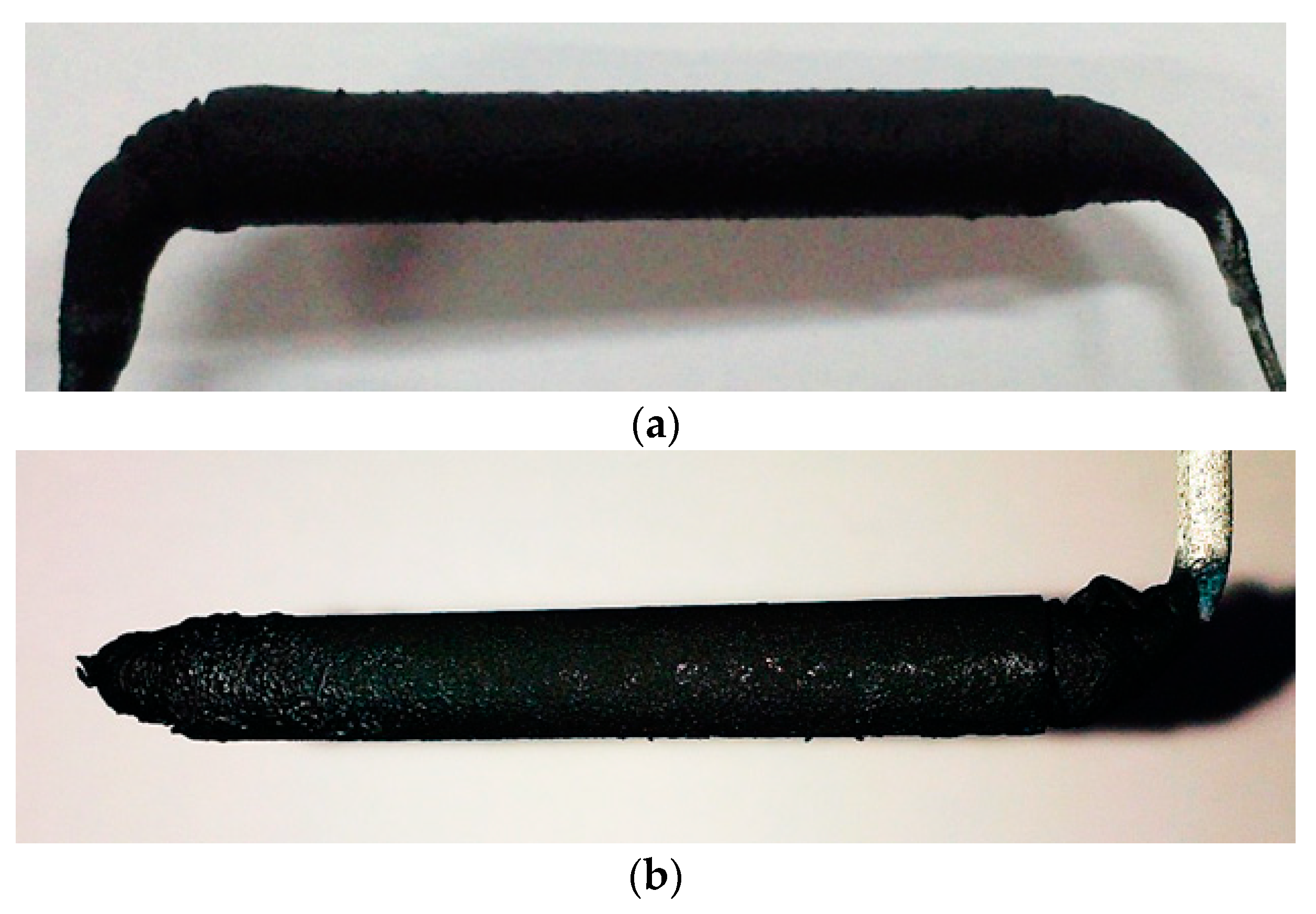
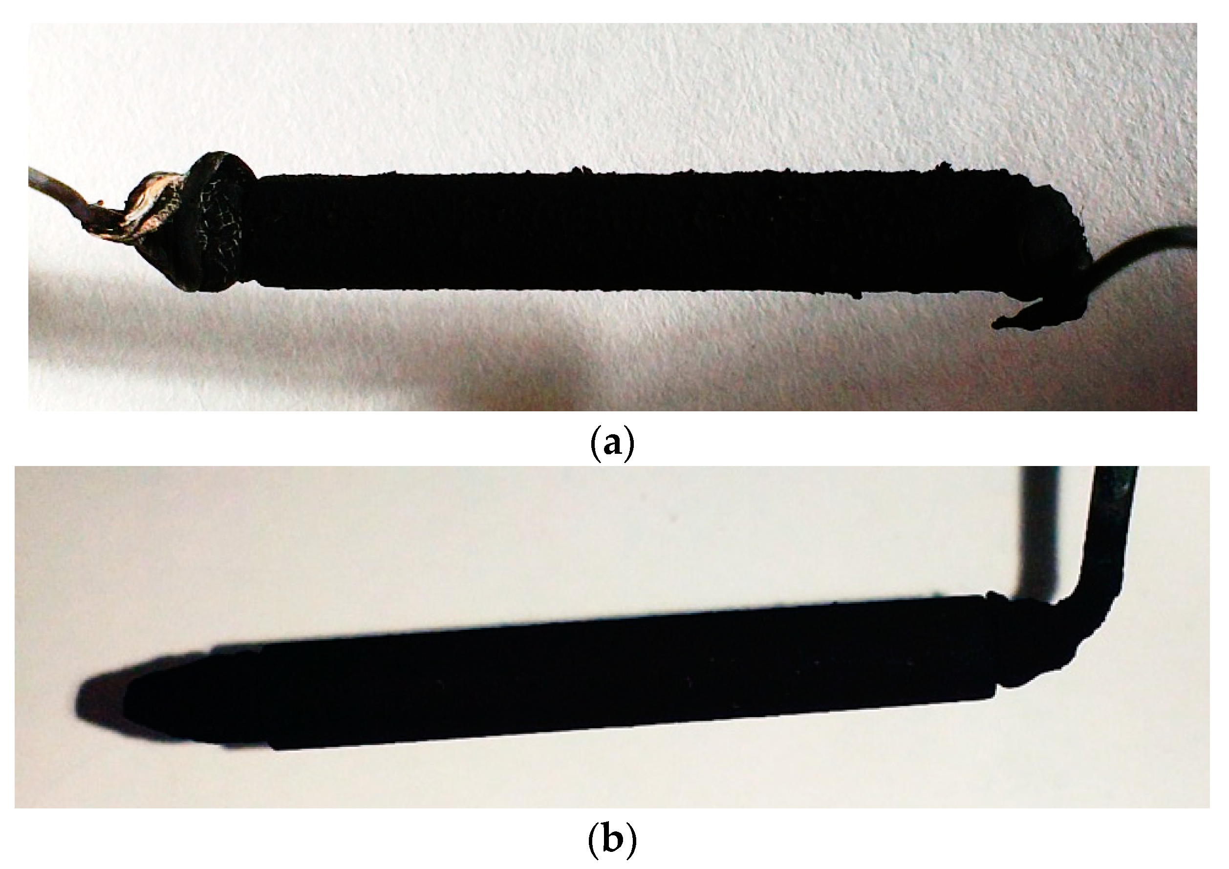
The diffusion layer and the catalytic layer, prepared manually, and the self-made device were evaluated on whether the surface coating is uniform and whether the surface has a large area of peeling. The coated diffusion layer is shown in Figure 12 and the coated catalytic layer is shown in Figure 13.
By observing Figure 12 and Figure 13, we can see that there are some uneven coating thicknesses and peeling areas on the manual coating. As shown in Figure 12a, the electrode diffusion layer coated manually has obvious slurry accumulation on the left end. Contrarily, as shown in Figure 12b, the diffusion layer coated by the self-made device has better surface uniformity due to the fact that it was continuously rotated during the coating process and the slurry is uniformly stressed in all directions. As shown in Figure 13a, the electrode catalytic layer coated manually will have the phenomenon of lifting and peeling, but the surface of the electrode catalytic layer coated by the self-made device is smooth and tidy.
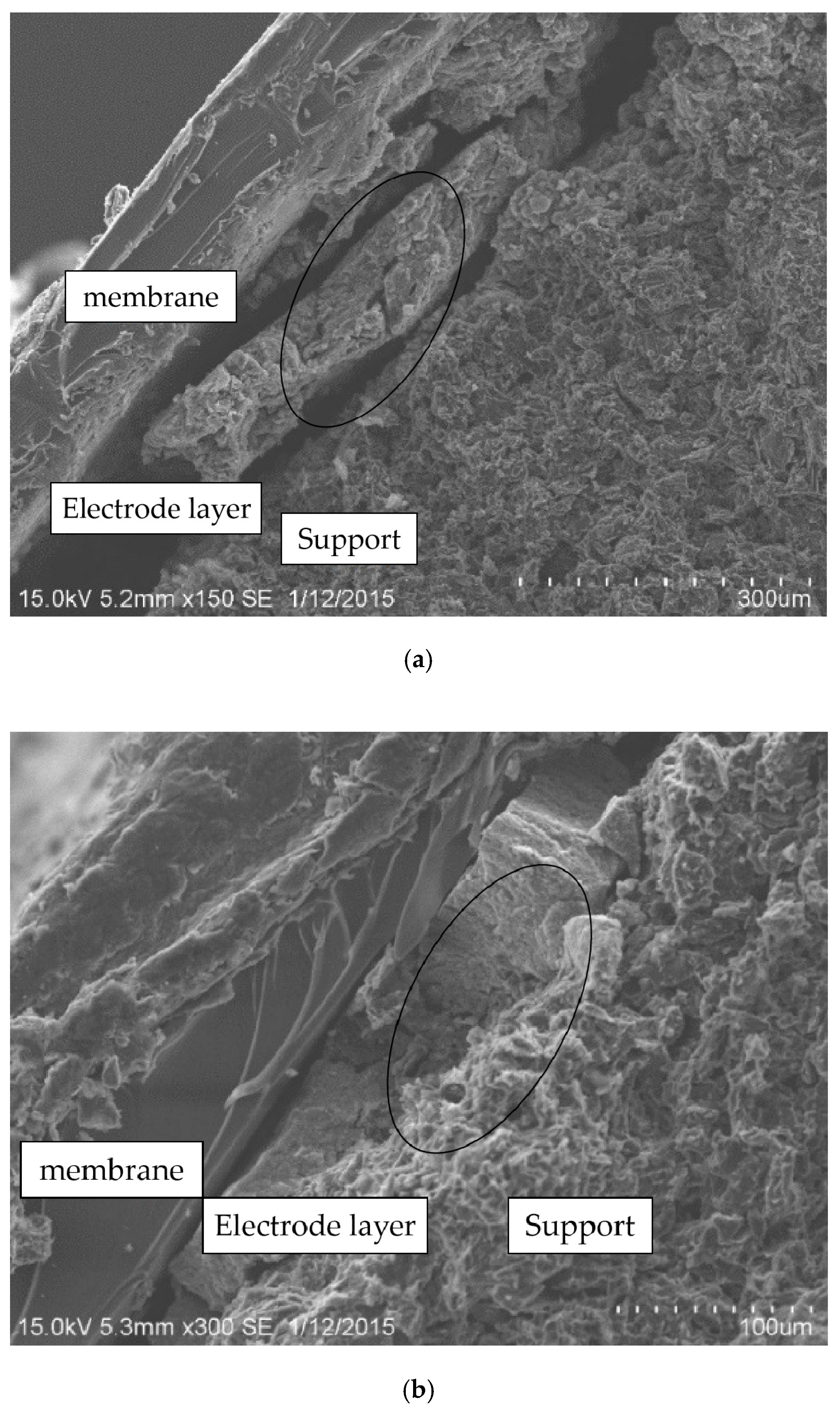
A scanning electron microscope (SEM, the S-3400 type, produced by Hitachi, Ltd., Tokyo, Japan) was used to scan the cross-section of the coated electrode, and the SEM images [37] were obtained as shown in Figure 14. It can be seen from Figure 14 that the structure of the electrode layer coated manually is loose. The bonding force between the electrode layer material and the support material is insufficient, and there is a clear gap between the two layers, which causes peeling. However, the electrode layer coated by the self-made device has a compact structure, the bonding force between the electrode layer material and the support material is strong, and there is no obvious gap between the two layers.

3.2.4. Comparison of Electrochemical Performance

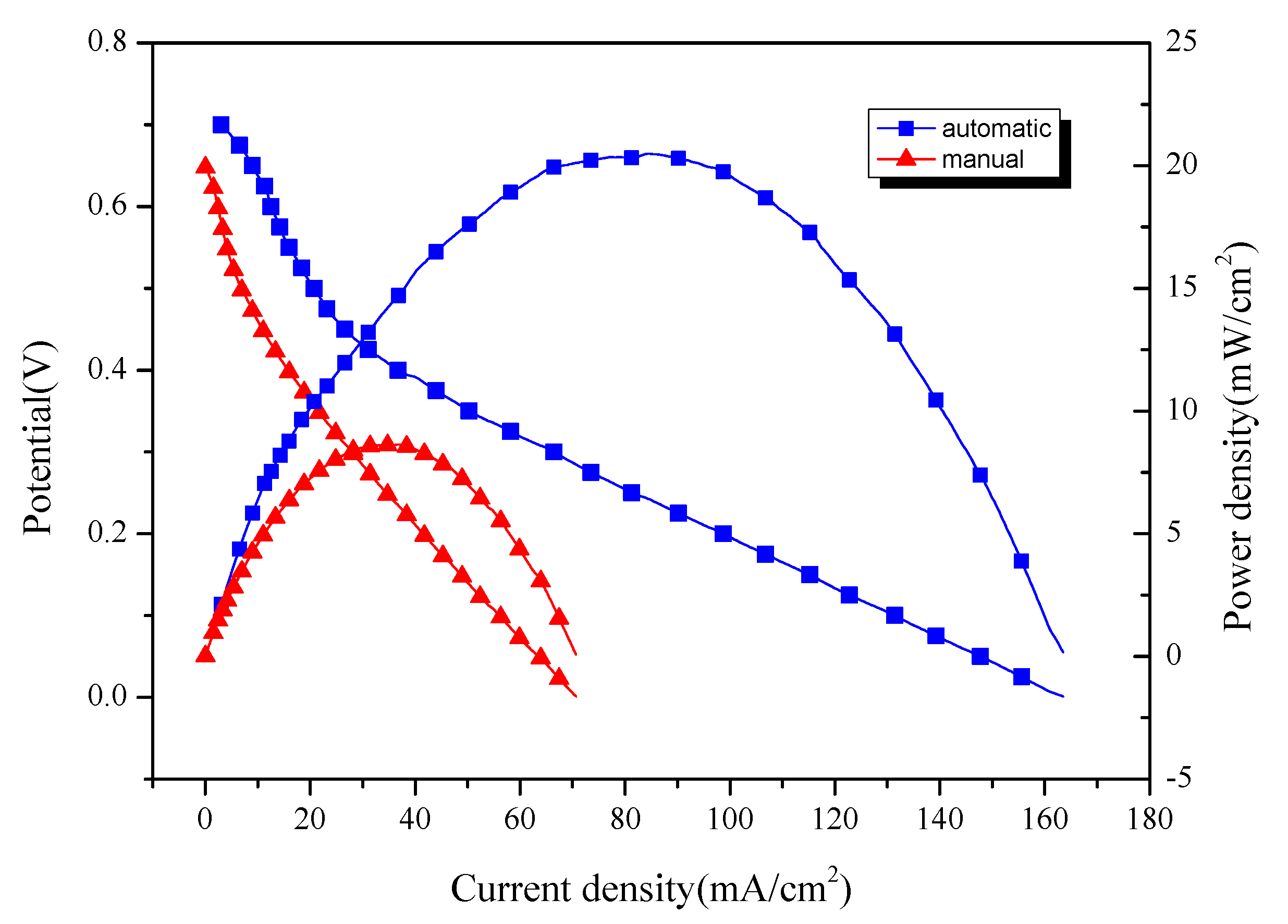
The electrodes coated by the manual and device were assembled, respectively, and the electrochemical performance test was performed. A 1 mol/L H2SO4 + 0.5 mol/L CH3OH solution was used as the anolyte, a Nafion 117 membrane was selected as the proton exchange membrane and 100 mL/min O2 was passed into the structure as an oxidant. A constant temperature water bath was used to heat the bath to ensure that the operating temperature is stable, then the power density of the single cell was measured. The results are shown in Figure 15. It can be seen that the power density of the electrode generated by the self-made device can reach 20.50 mW/cm2. Under the same conditions, the power density of the manually coated electrode is only 8.63 mW/cm2. The power density of the DMFC obtained using the self-made device is 2.4 times that of the manual coating.

4. Conclusions

(1)
A device was designed and fabricated for coating tubular electrodes, and thermal stress coupling experiments were conducted by using ANSYS software, and the optimal coating process of the device was determined by comparing the actual coating data. The optimal coating environment temperature is 30–40 °C, and the better coating speed is 6.67 r/min.
(2)
In terms of macroscopic morphology, the surface uniformity of electrodes coated by self-made devices is better than the electrodes coated manually. The structure of manually coated electrode layers are loose, and are separated from the electrode support and the PEM. Electrode layers coated by the self-made device have a compact structure and a good fit with the electrode support and the PEM.
(3)
Through different comparative tests, the optimal power generation experiment conditions are determined as: the PEM is Nafion 117, the electrolyte is 1 mol/L H2SO4 + 0.5 mol/L CH3OH, and the reaction temperature is stable. The power generation experiment shows that the power density of the electrode coated by the self-made device can reach 20.50 mW/cm2, which is about 2.4 times that of the electrode coated manually.

5. Patents

The author has been engaged in fuel cell related work for many years, and the three Chinese invention patents related to this article have been granted, and the patent numbers are CN103418530B, CN103427093B and CN100590923C.

Author Contributions

Conceptualization, H.N. and F.L.; methodology, S.L.; validation, J.Z. and Y.P.; formal analysis, H.N. and S.L.; investigation, J.Z. and X.W.; resources, H.N. and F.L.; writing—original draft, J.Z.; writing—review and editing, H.N.; visualization, J.Z.; supervision, H.N. All authors have read and agreed to the published version of the manuscript.

Funding

This research was supported by A Priority Academic Program Development of Jiangsu Higher Education Institutions (PAPD), Nantong Applied Research Project, grant number JC2018115 and JC2019129, Ministry of Education’s Cooperative Education Project, grant number 201901189019.

Conflicts of Interest

The authors declare no conflict of interest.

References

  1. Omer, A.M. Energy, environment and sustainable development. Renew. Sustain. Energy Rev. 2008, 12, 2265–2300. [Google Scholar] [CrossRef]
  2. Ni, H.; Zhang, J.; Lv, S.; Wang, X.; Zhu, Y.; Gu, T. Preparation and Performance Optimization of Original Aluminum Ash Coating Based on Plasma Spraying. Coatings 2019, 9, 770. [Google Scholar] [CrossRef] [Green Version]
  3. Shuaishuai, L.; Jiaqiao, Z.; Hongjun, N.; Xingxing, W.; Yu, Z.; Tao, G. Study on Preparation of Aluminum Ash Coating Based on Plasma Spray. Appl. Sci. 2019, 9, 4980. [Google Scholar]
  4. Lv, S.; Zhang, J.; Ni, H.; Wang, X.; Zhu, Y.; Chen, L. Study on the Coupling Relationship of Low Temperature Fluidity and Oxidation Stability of Biodiesel. Appl. Sci. 2020, 10, 1757. [Google Scholar] [CrossRef] [Green Version]
  5. Liu, H.; Song, C.; Zhang, L.; Zhang, J.; Wang, H.; Wilkinson, D.P. A review of anode catalysis in the direct methanol fuel cell. J. Power Sources 2006, 155, 95–110. [Google Scholar] [CrossRef]
  6. Li, L.; Zhang, J.; Wang, Y. Sulfonated poly (ether ether ketone) membranes for direct methanol fuel cell. J. Membr. Sci. 2003, 226, 159–167. [Google Scholar] [CrossRef]
  7. Nguyen, N.T.; Chan, S.H. Micromachined polymer electrolyte membrane and direct methanol fuel cells—A review. J. Micromechanics Microengineering 2006, 16, R1. [Google Scholar] [CrossRef]
  8. Martinaiou, I.; Videla, A.H.A.M.; Weidler, N. Activity and degradation study of an Fe-NC catalyst for ORR in Direct Methanol Fuel Cell (DMFC). Appl. Catal. B Environ. 2020, 262, 118217. [Google Scholar] [CrossRef]
  9. Xing, L.; Shi, W.; Su, H.; Xu, O.; Das, P.K.; Mao, B.; Scott, K. Membrane electrode assemblies for PEM fuel cells: A review of functional graded design and optimization. Energy 2019, 177, 445–464. [Google Scholar] [CrossRef]
  10. Holzapfel, P.; Bühler, M.; Van, P.C. Directly coated membrane electrode assemblies for proton exchange membrane water electrolysis. Electrochem. Commun. 2020, 110, 106640. [Google Scholar] [CrossRef]
  11. Ni, H.; Wang, K.; Lv, S.; Wang, X.; Zhuo, L.; Zhang, J. Effects of Concentration Variations on the Performance and Microbial Community in Microbial Fuel Cell Using Swine Wastewater. Energies 2020, 13, 2231. [Google Scholar] [CrossRef]
  12. Khamseh, S.; Alibakhshi, E.; Ramezanzadeh, B.; Saria, M.G. A tailored pulsed substrate bias voltage deposited (aC: Nb) thin-film coating on GTD-450 stainless steel: Enhancing mechanical and corrosion protection characteristics. Chem. Eng. J. 2020, 404, 126490. [Google Scholar] [CrossRef]
  13. Xu, P.; Meng, G.; Pershin, L.; Mostaghimi, J.; Coyle, T.W. Control of the hydrophobicity of rare earth oxide coatings deposited by solution precursor plasma spray by hydrocarbon adsorption. J. Mater. Sci. Technol. 2020, 62, 107–118. [Google Scholar] [CrossRef]
  14. De Crescenzo, C.; Karatza, D.; Musmarra, D.; Chianese, S.; Baxevanis, T.; Dalla, P.T.; Exarchos, D.A.; Dassios, K.G.; Matikas, T.E. Ni-Ti shape memory alloy coatings for structural applications: Optimization of HVOF spraying parameters. Adv. Mater. Sci. Eng. 2018, 7867302. [Google Scholar] [CrossRef] [Green Version]
  15. Ni, H.; Zhang, J.; Lv, S.; Wang, X.; Zhang, S.; Zhao, N.; Gu, H.; Li, B.; Jiang, J. Design and Study on a Self-Controlled Walking Car. In Proceedings of the 2018 3rd International Conference on Mechanical, Control and Computer Engineering (ICMCCE), Huhhot, China, 14–16 September 2018; pp. 281–285. [Google Scholar] [CrossRef]
  16. Ni, H.; Pei, Y.; Lv, S.; Ma, J.; Wang, X. Design of Coating Device for Circular Direct Methanol Fuel Cell Cathode. J. Nantong Univ. 2013, 12, 26–28. (In Chinese) [Google Scholar]
  17. Shin, H.J.; Oytun, F.; Kim, J.W. Cost-effective centrifuge coating method for silver nanowire-based transparent conducting electrode. Electrochim. Acta 2020, 337, 135839. [Google Scholar] [CrossRef]
  18. Mellbring, O.; Kihlman Øiseth, S.; Krozer, A. Spin coating and characterization of thin high-density polyethylene films. Macromolecules 2001, 34, 7496–7503. [Google Scholar] [CrossRef]
  19. Fierro, S.; Comninellis, C. Kinetic study of formic acid oxidation on Ti/IrO2 electrodes prepared using the spin coating deposition technique. Electrochim. Acta 2010, 55, 7067–7073. [Google Scholar] [CrossRef]
  20. Haselrieder, W.; Westphal, B.; Bockholt, H. Measuring the coating adhesion strength of electrodes for lithium-ion batteries. Int. J. Adhes. Adhes. 2015, 60, 1–8. [Google Scholar] [CrossRef]
  21. Pennestrı, E.; Valentini, P.P. A review of formulas for the mechanical efficiency analysis of two degrees-of-freedom epicyclic gear trains. J. Mech. Des. 2003, 125, 602–608. [Google Scholar] [CrossRef]
  22. Liu, X.; Yang, Y.; Zhang, J. Effects of tooth-crack-induced mesh stiffness on fault signals of a planetary gear train. Procedia Comput. Sci. 2017, 109, 785–792. [Google Scholar] [CrossRef]
  23. Behle, S.; Lüettringhaus-Henkel, A.; Eimann, P. Process and Apparatus for the Plasma Coating of Workpieces with Spectral Evaluation of the Process Parameters. U.S. Patent 8,397,667, 19 March 2013. [Google Scholar]
  24. Janqour, L.M.; Sarabi, A.A. Optimization of coating process parameters and surface characterization for vanadium-based conversion coating on 2024 aluminum alloy. Prog. Org. Coat. 2019, 133, 33–43. [Google Scholar] [CrossRef]
  25. Röder, F.; Braatz, R.D.; Krewer, U. Direct coupling of continuum and kinetic Monte Carlo models for multiscale simulation of electrochemical systems. Comput. Chem. Eng. 2019, 121, 722–735. [Google Scholar] [CrossRef]
  26. Wu, D.; Zhong, W. A new strategy for anchoring a functionalized graphene hydrogel in a carbon cloth network to support a lignosulfonate/polyaniline hydrogel as an integrated electrode for flexible high areal-capacitance supercapacitors. J. Mater. Chem. A 2019, 7, 5819–5830. [Google Scholar] [CrossRef]
  27. Li, F.; Xing, J.; Liu, Y. Thermal Analysis and Stress Analysis of the Heat-Exchange Pipe Based on ANSYS. In Proceedings of the 2011 Fourth International Conference on Information and Computing, Phuket Island, Thailand, 25–27 April 2011; IEEE: New York, NY, USA, 2011; pp. 283–285. [Google Scholar]
  28. Ni, H.; Zhang, J.; Zhao, N.; Wang, C.; Lv, S.; Ren, F.; Wang, X. Design on the Winter Jujubes Harvesting and Sorting Device. Appl. Sci. 2019, 9, 5546. [Google Scholar] [CrossRef] [Green Version]
  29. Gao, J.L.; Du, Q.G.; Zhang, X.D. Thermal stress analysis and structure parameter selection for a Bi2Te3-based thermoelectric module. J. Electron. Mater. 2011, 40, 884–888. [Google Scholar] [CrossRef]
  30. Tyona, M.D. A comprehensive study of spin coating as a thin film deposition technique and spin coating equipment. Adv. Mater. Res. 2013, 2, 181. [Google Scholar] [CrossRef] [Green Version]
  31. Zhang, J.D.; Hao, N.; Lu, L. High-efficient preparation and screening of electrocatalysts using a closed bipolar electrode array system. J. Electroanal. Chem. 2019, 832, 1–6. [Google Scholar] [CrossRef]
  32. DeBonis, D.; Mayer, M.; Omosebi, A. Analysis of mechanism of Nafion® conductivity change due to hot pressing treatment. Renew. Energy 2016, 89, 200–206. [Google Scholar] [CrossRef]
  33. Govindarasu, R.; Somasundaram, S. Studies on Influence of Cell Temperature in Direct Methanol Fuel Cell Operation. Processes 2020, 8, 353. [Google Scholar] [CrossRef] [Green Version]
  34. Colpan, C.O.; Ouellette, D.; Glüsen, A. Reduction of methanol crossover in a flowing electrolyte-direct methanol fuel cell. Int. J. Hydrog. Energy 2017, 42, 21530–21545. [Google Scholar] [CrossRef]
  35. Abrego-Martínez, J.C.; Moreno-Zuria, A.; Wang, Y. Fabrication and evaluation of passive alkaline membraneless microfluidic DMFC. Int. J. Hydrog. Energy 2017, 42, 21969–21975. [Google Scholar] [CrossRef]
  36. Vasile, N.S.; Videla, A.H.A.M.; Simari, C. Influence of membrane-type and flow field design on methanol crossover on a single-cell DMFC: An experimental and multi-physics modeling study. Int. J. Hydrog. Energy 2017, 42, 27995–28010. [Google Scholar] [CrossRef]
  37. Mushtaq, M.; Wasim, M.; Naeem, M.A.; Khan, M.R.; Yue, S.; Saba, H.; Hussain, T.; Siddiqui, M.Q.; Farooq, A.; Wei, Q. Composite of PLA Nanofiber and Hexadecyl Trimethyl-Ammonium Chloride-Modified Montmorillonite Clay: Fabrication and Morphology. Coatings 2020, 10, 484. [Google Scholar] [CrossRef]
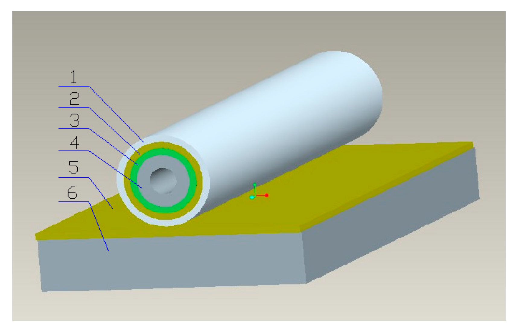
Figure 1. Three-dimensional structure of tubular electrode of direct methanol fuel cell (DMFC).
Coatings 10 00830 g001
Figure 2. Coating device: (a) Three-dimensional design drawing of the device; (b) Physical picture of the device.
Coatings 10 00830 g002
Figure 3. Transmission mechanism of the coating device.
Coatings 10 00830 g003
Figure 4. Simulation of coating deformation at different temperatures: (a) 25 °C; (b) 30 °C; (c) 35 °C; (d) 40 °C; (e) 45 °C; (f) 50 °C.
Coatings 10 00830 g004aCoatings 10 00830 g004b
Figure 5. Deformation of the electrode at different temperatures.
Coatings 10 00830 g005
Figure 6. The weight of the electrode in each period under the influence of different coating speeds: (a) No. 1 electrode; (b) No. 2 electrode; (c) No. 3 electrode.
Coatings 10 00830 g006
Figure 7. The electrode preparation process.
Coatings 10 00830 g007
Figure 8. The membrane electrode assembly (MEA) of a single cell of tubular DMFC.
Coatings 10 00830 g008
Figure 9. Polarization curves of the DMFC in different electrolytes.
Coatings 10 00830 g009
Figure 10. Polarization curve of DMFC under different oxidants.
Coatings 10 00830 g010
Figure 11. Polarization curves of DMFC with different proton exchange membranes (PEMs).
Coatings 10 00830 g011
Figure 12. Coating of the diffusion layer: (a) the diffusion layer coated manually; (b) the diffusion layer coated by self-made device.
Coatings 10 00830 g012
Figure 13. Coating of the catalytic layer: (a) the catalytic layer coated manually; (b) the catalytic layer coated by self-made device.
Coatings 10 00830 g013
Figure 14. SEM image of electrode cross-section: (a) the electrode coated manually (b) the electrode coated by self-made device.
Coatings 10 00830 g014
Figure 15. Power density curves of single cells obtained by different coating methods.
Coatings 10 00830 g015
Table 1. Main raw materials and reagents.
Raw MaterialType or ParameterManufacturer
Graphite tubePurity: 99.999%Beijing Jixing Shengan Industry and Trade Co., Ltd. (Beijing, China)
MCMB/G tubePorosity: 40%Laboratory self-made
TonerC, Vulcan XC-72RCabot corporation (Boston, MA, USA)
PTFE emulsion (analytical grade)60 wt.% PTFEDuPont (Wilmington, DE, USA)
Pt/C catalystPt/CShanghai Hesen Electric Co., Ltd. (Shanghai, China)
Nafionemulsion (analytical grade)5 wt.% NafionDuPont (Wilmington, DE, USA)
Graphite platePurity: 99.99%Beijing Jixing Shengan Industry and Trade Co., Ltd. (Beijing, China)
PtRu/C catalystPtRu/CShanghai Hesen Electric Co., Ltd. (Shanghai, China)
Table 2. Material performance parameters.
ParametersFunctional Layers
Electrode SupportElectrode LayerPEM
Elastic moduli/Pa10.8 × 1066.13 × 10680 × 106
Thermal expansion coefficient5.49 × 10−622 × 10−6520 × 10−6
Thickness/mm1.50.20.183
Table 3. Weight gain per unit time at different coating speeds.
No.Coating Speed (r/min)Average Weight Gain (mg)
16.673.00 ± 1.43
102.53 ± 1.34
26.673.08 ± 1.17
102.45 ± 1.64
36.673.06 ± 1.20
101.67 ± 0.96
Table 4. Optimal experimental parameters.
NameParameters
Temperature80 °C
Electrolyte1 mol/L H2SO4 + 0.5 mol/L CH3OH solution
OxidantO2, access rate 100 mL/min
PEMNafion 117