Article

Nonlinear Characteristics of Complementary Resistive Switching in HfAlOx-Based Memristor for High-Density Cross-Point Array Structure

Division of Electronics and Electrical Engineering, Dongguk University, Seoul 04620, Korea
*
Author to whom correspondence should be addressed.
Coatings 2020, 10(8), 765; https://doi.org/10.3390/coatings10080765
Submission received: 16 July 2020 / Revised: 2 August 2020 / Accepted: 4 August 2020 / Published: 6 August 2020
(This article belongs to the Section Thin Films)

Abstract

:
In this work, we present the nonlinear current–voltage (IV) characteristics of a complementary resistive switching (CRS)-like curve from a HfAlOx-based memristor, used to implement a high-density cross-point array. A Pt/HfAlOx/TiN device has lower on-current and larger selectivity compared to Pt/HfO2/TiN or Pt/Al2O3/TiN devices. It has been shown that the on-current and first reset peak current after the forming process are crucial in obtaining a CRS-like curve. We demonstrate transient CRS-like characteristics with high nonlinearity under pulse response for practical applications. Finally, after finding the optimal conditions for high selectivity, the calculated read margin proves that a Pt/HfAlOx/TiN device with a CRS-like curve is most suitable for use in a high-density cross-point array. Our results suggest that the built-in selector properties in a Pt/HfAlOx/TiN single layer device offer considerable potential in terms of the simplicity of the processes involved in the cross-point structure.

1. Introduction

Memristors, in the context of cross-point array structure, have received great attention recently with a view to explore fast switching speed, high endurance, long retention, high-density memory, and low-power operation [1,2,3]. Especially, the resistive switching memory (RRAM) provides diverse resistive switching types depending on the resistive switching material and electrodes. In unipolar resistive switching (URS), the set and reset processes happen in the same polarity. The reset process occurs by Joule heating at high current [4]. On the other hand, in bipolar resistive switching (BRS), the set and reset processes occur in opposite polarity. Reset switching is dominantly driven by the electric field [5]. In CRS, the reset process occurs after the set process at both polarities [6]. In a cross-point array structure, a memristor and selector element can be vertically integrated, making them an ideal candidate for 4F2 (F is feature size). If the feature size (F) can be reduced during device size scaling, this is the most efficient design in terms of cell density [7]. Recently, structures that can stack cross-point structures up to the second floor and the fourth floor have been introduced [8], so a vertical memristor structure is possible, like a 3D vertical type NAND flash for ultra high-density memory [9]. Moreover, a cross-point memristor array could be used in a synaptic array in a hardware-based neuromorphic system [10,11,12,13,14]. The synaptic weight (i.e., conductance) of the memristor can be updated according to an applied pulse signal. A memristor array has the advantage of being capable of running at low voltages with good speed, thereby enabling low energy operation for synapse applications [10,11,12,13,14]. However, the cross-point structure cannot avoid the problem of a sneak current path when using a memory cell with linear IV, which limits the size of the array [15,16,17,18]. The main portion of sneak current paths are those that flow through the on-state memory cell. Therefore, in order to prevent this, the nonlinear IV characteristics should be addressed. Therefore, connecting a selector element to each memory cell to ensure nonlinear IV characteristics is one solution to mitigate the sneak current path problem [19,20,21,22]. There are several candidates for an individual selector device. The ovonic threshold switching (OTS) type shows good cycle endurance but selectivity is not high enough and is a little complicated for integration with a complementary metal–oxide–semiconductor (CMOS) process [23]. The insulator–metal transition type such as VO2 operates as a selector at only high temperature [24]. The Si PN diode type selector has disadvantages in terms of the difficulty of the process in 3D type and the compatibility with only URS type memristors [25]. Another way is to achieve nonlinear characteristics in the memristor cell itself without a selector connection [26,27,28,29,30,31]. This approach has the advantage of being simple without needing a connection to a selector. In fact, since the integration of a selector on the memory device requires the insertion of a barrier metal in the middle, the etching process can be complicated [32]. However, the selectivity in the metal–insulator–metal (MIM) structure is not enough in comparison with independent selector connection.
In this paper, we study the nonlinear and stable CRS-like characteristics of a HfAlOx-based RRAM device. Pt/HfAlOx/TiN devices have the advantage that their CRS-like characteristics are available in a single insulator layer structure (metal–insulator–metal, MIM) compared to the anti-serial structure that arises due to the fabrication process with metal–insulator–metal–insulator–metal (MIMIM) devices. Until now, CRS characteristics from MIM or metal–insulator–insulator–metal (MIIM) structure devices without a middle metal layer have only been reported very rarely [33,34,35,36]; in addition, pulse operation in CRS has also only been very rarely verified. In this study, CRS characteristics are demonstrated in a HfAlOx thin film formed by well controlled atomic layer deposition (ALD). Moreover, lower current and higher nonlinear operation were achieved in the Pt/HfAlOx/TiN device compared to Pt/HfO2/TiN devices. Finally, we demonstrate the pulse operation for CRS after finding two important switching parameters to differentiate BRS and CRS.

2. Experimental Procedure

We fabricated three types of high-k dielectric-based memristor devices with Pt/HfO2/TiN, Pt/Al2O3/TiN, and Pt/HfAlOx/TiN structures in the following manner. A 100-nm-thick TiN layer was prepared on a SiO2/Si wafer using a physical vapor deposition system. All high-k films with 7-nm thickness were accurately deposited by ALD. The HfO2 film was reacted with tetrakis-ethylmethylamino hafnium (TEMAHf) and H2O as precursors at 280 °C. In total, 105 cycles were conducted for 7 nm deposition, where one cycle was composed of TEMAHf (0.5 s)-purge (35 s)-H2O (0.3 s)- and purge (35 s). Al2O3 was reacted with trimethylaluminum (TMA) and H2O at 200 °C. A total of 60 cycles were performed for 7 nm film thickness, where one cycle was composed of TMA (0.2 s)-purge (15 s)-H2O (0.2 s)- and purge (15 s). For the HfAlOx film, 1 cycle of (TMA + H2O), then, 2 cycles of (TEMAH + H2O) were alternately deposited a total 28 times for 7 nm thickness. Here, the ratio between two materials (Hf and Al) can be controlled by cycling number. The Pt top electrode with a thickness of 100 nm was deposited by an electron beam (e-beam) evaporator and patterned by a shadow mask containing circular patterns with a diameter of 100 μm. The electrical properties were characterized in DC mode using a Keithley 4200-SCS semiconductor parameter analyzer (Keithley, Beaverton, OR, USA) and in pulse mode using a 4225-PMU ultrafast module. During the measurements, a bias voltage and pulse were applied to the Pt top electrode, while the TiN bottom electrode was grounded. The cross-sectional transmission electron microscopy (TEM) images, which were prepared by a common focus ion beam method, utilizing FEI Quanta 3D FEG dual-beam instrument (Irvine Materials Research Institute, Irvine, CA, USA), were conducted by JEOL JEM-2100F TEM (Irvine Materials Research Institute, Irvine, CA, USA).

3. Results and Discussion

Figure 1a shows a TEM image of the Pt/HfAlOx/TiN device; the thin film thickness of about 7 nm is confirmed. The polycrystalline TiN and amorphous HfAlOx are observed in the TEM image. Additionally, the elements (Ti, N, Hf, Al, O, and Pt) were detected in each layer of the Pt/HfAlOx/TiN device using an energy dispersive spectroscopy (EDS) depth profile. It is noted that some overlap between each element is observed, due to the very thin HfAlOx layer. The ratio between Hf and Al cannot be varied by controlling the cycling numbers of TEMAHf and TMA during the ALD deposition. If the Al content is increased, the insulated properties are strengthened due to the high band gap of Al2O3.
Figure 2a–c show the repeated IV characteristics of Pt/HfO2/TiN, Pt/Al2O3/TiN, and Pt/HfAlOx/TiN devices after the electroforming and first reset in the first cycle. The linear scale of the IV curve is also presented to highlight the nonlinear characteristics for three devices in the inset of Figure 2a–c. The Pt/HfO2/TiN device shows quite a nonlinear curve in the positive region during its on-state in the inset of Figure 2a. This is typical asymmetric conducting filament evolution behavior with the applied bias voltage and polarity from the HfO2 layer [37]. The Pt/Al2O3/TiN device shows BRS with a relatively linear on-state in Figure 2b. The SET process occurs in the negative region where the off-state changes to the on-state for BRS. A self-compliance phenomenon in which the current slowly increases with increasing voltage after the current jumps rapidly to about 1 mA is observed. The reset process occurs under a positive voltage sweep, where the on-state changes to the off-state. The Pt/HfAlOx/TiN device shows a CRS-like curve in the positive region of Figure 2c. We can clearly observe a CRS-like curve on the linear scale (inset) where the current increases then decreases again with increasing voltage after the SET process takes place in the negative region.
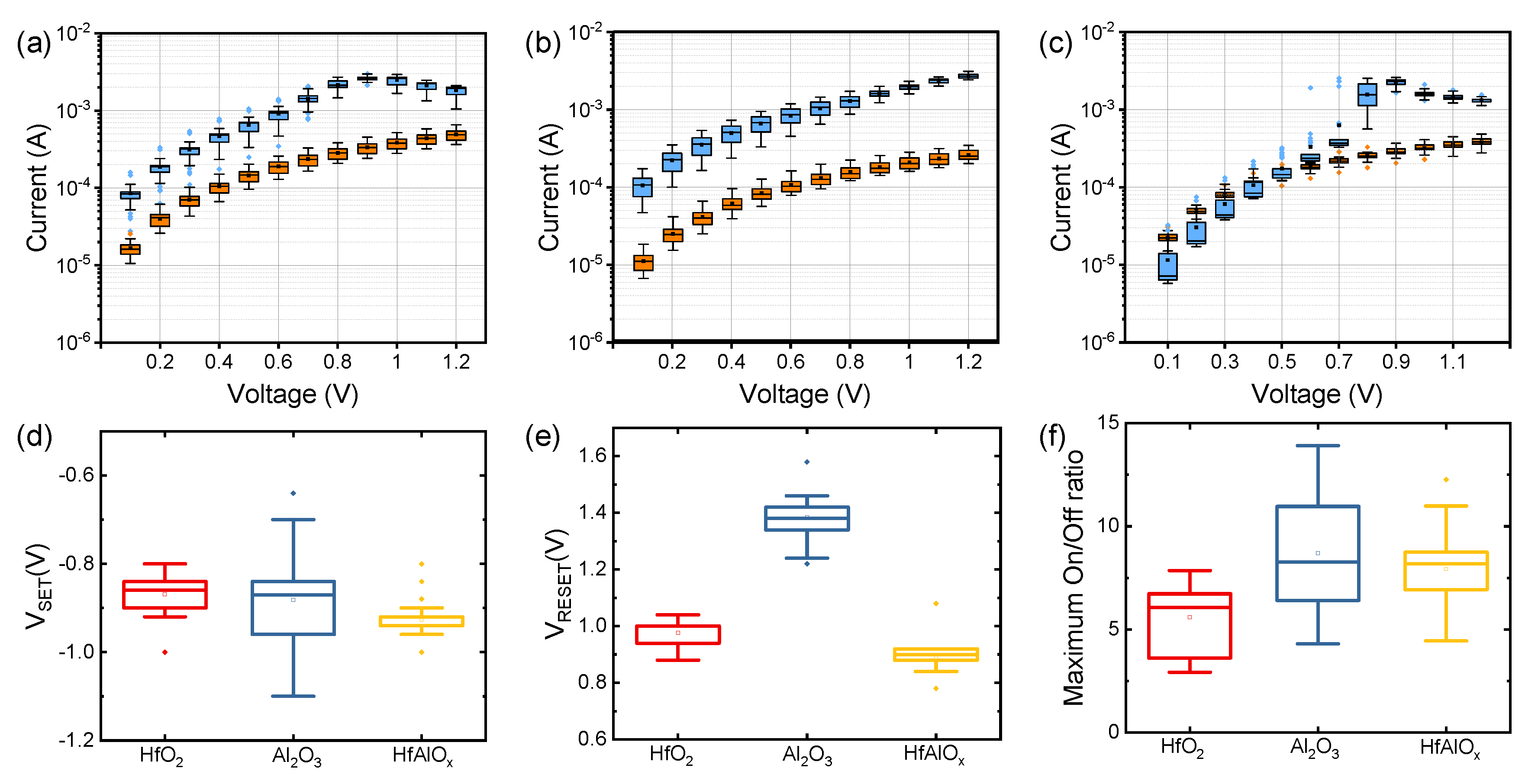
Figure 3a–c show the cycle-to-cycle distribution as a function of voltage for the respective Pt/HfO2/TiN, Pt/Al2O3/TiN, and Pt/HfAlOx/TiN devices. The on-state current of the Al2O3 device with the applied voltage is almost linear characteristic. The HfAlOx device shows a fairly uniform cycle-to-cycle distribution at the read voltage (VREAD), with an even jump of about 0.9 V. The variability of turn-on voltage is very important for setting the VREAD. It is noted that the difference between on-state current and off-state current at the low voltage region is not noticeable due to the suppression of on-state current after the set process. This property is very desirable to implement high-density memory applications and we will discuss this in more depth later. In addition, the HfAlOx device has an on/off ratio, SET voltage (VSET), and RESET voltage (VRESET) that are comparable with the HfO2 and Al2O3 devices in Figure 3d–f. However, relatively high Vread is required to obtain a high on/off ratio in the HfAlOx device.
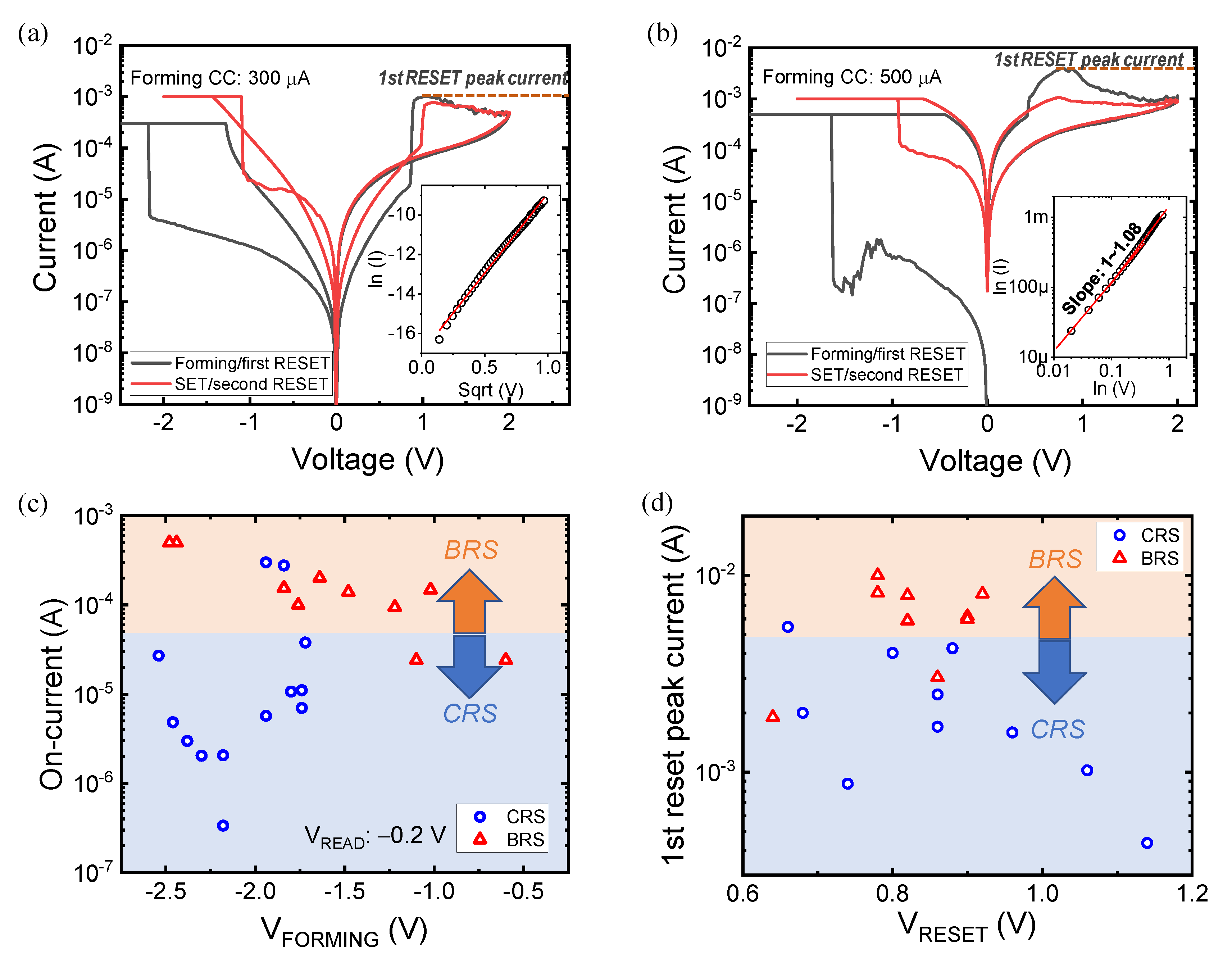
Next, we investigate the conditions for obtaining a stable CRS-like curve in the HfAlOx device. Figure 4a,b show the forming of the first RESET, subsequent SET, and second RESET I–V curves for the Pt/HfAlOx/TiN device at forming compliance currents (CC) of 300 and 500 µA. It should be noted that after forming, additional current rises occur before the RESET process shown in Figure 4a. This curve is similar to the CRS-like curve that is helpful in reducing the sneak current path in cross-point array structures. Figure 4b shows a typical bipolar resistive switching (BRS) curve after the forming and first RESET processes. We found the control parameters that determine CRS and BRS through a statistical approach. Figure 4c shows the on-current at a read voltage of −0.2 V as a function of the forming voltage for the Pt/HfAlOx/TiN device. When a low on-current flows through the insulator after forming, the current rapidly increases before RESET occurs during positive bias. It can be seen indirectly how conducting defects are formed by the on-state current. A CRS-like curve is achieved when weak conducting filament is formed without any severe overshoots during the forming process [31]. Figure 4d shows the first RESET peak current as a function of RESET voltage (VRESET) for the Pt/HfAlOx/TiN device. When a first peak reset current of less than about 4 mA is observed, stable CRS processes tend to be observed from the second curve. This suggests that the high overshoot current creates a lot of defects in the HfAlOx dielectric when the first RESET process occurs, and these can then affect subsequent switching. A high on-current leads to typical BRS from second switching. To find the different properties of the HfAlOx dielectric in the on-state between CRS and BRS, we investigate the conduction mechanism using a fitting process. The inset of Figure 4a shows a linear fitting of a CRS-like IV curve for ln(I) versus V1/2 in the on-state under a positive bias. The fitting result suggests that Schottky emission is the dominant mechanism; this is mainly determined by the interface between the HfAlOx and the TiN bottom electrode. Although electroforming occurs under a negative bias, since a sufficient number of defects were not formed inside the HfAlOx dielectric, the conduction can be determined by the interface according to the difference in work function between the TiN electrode and HfAlOx layer [38]. On the other hand, for BRS, Ohmic conduction is dominant under linear fitting for ln(I) versus ln(V) with a slope of about 1 in the on-state under a positive bias, as shown in the inset of Figure 4b. The fitting results support the theory that a lot of defects are generated inside HfAlOx during electroforming, and that thermally excited electrons move from one isolated state to the next state in the dielectric by hopping conduction [38].
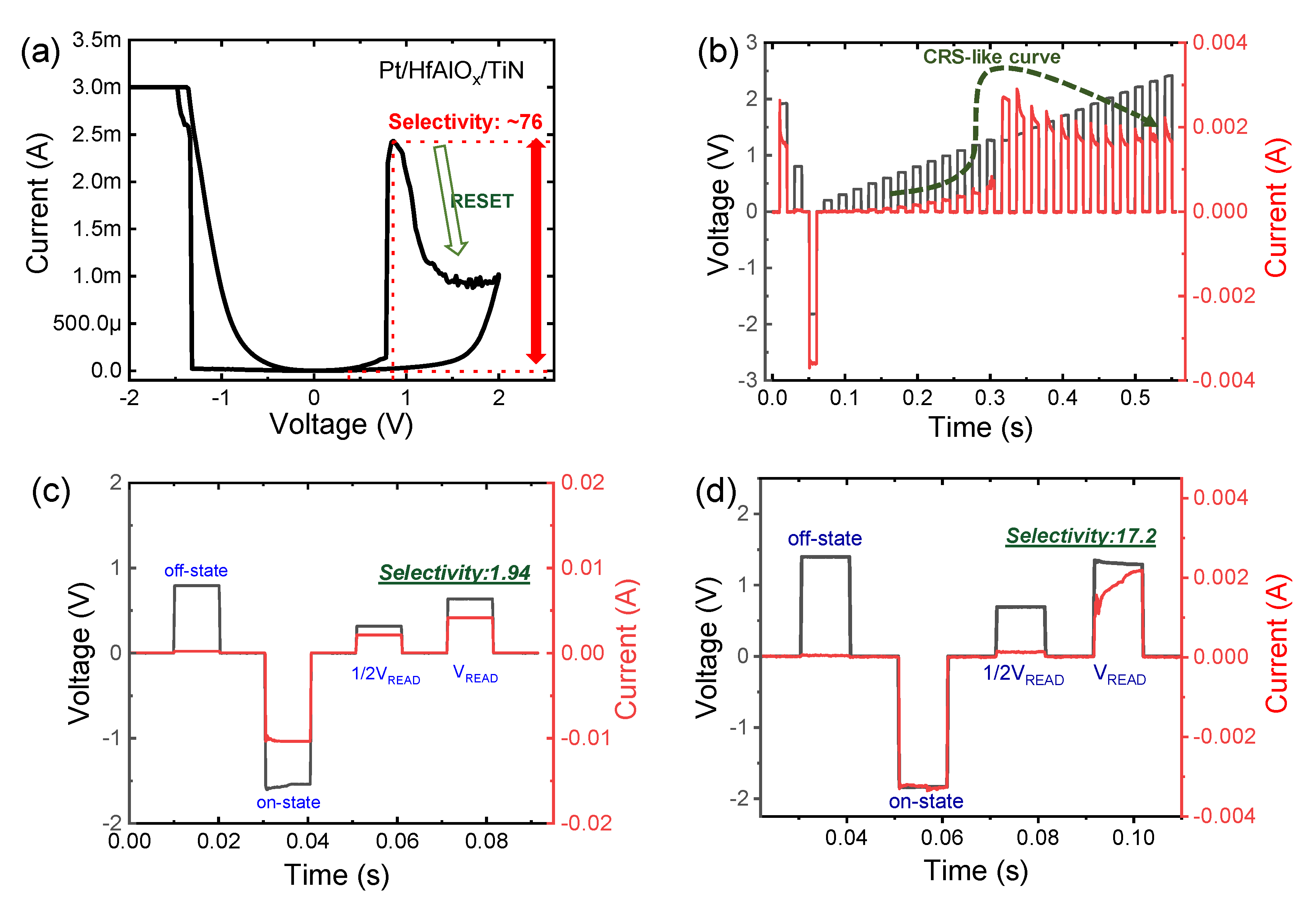
Next, to take advantage of the CRS-like IV curve in the cross-point structure, we take a closer look at the nonlinear characteristics. Figure 5a shows a CRS-like curve on a linear scale where the selectivity can be defined as the ratio between the current at VREAD and the current at 0.5 VREAD. The maximum selectivity is about 76 when we take the peak current to be a VREAD of 0.88 V. The transient characteristics are confirmed by the pulse response during practical operation. In order to obtain CRS-like motion, a series of pulses with different amplitudes and polarity that are organized systematically were applied to the Pt/HfAlOx/TiN device in Figure 5b. After being SET by a pulse with a large amplitude and a negative polarity, a CRS-like curve is observed as the voltage of the positive amplitude gradually increases. A selectivity of about 17.2 was obtained when 1/2 VREAD voltage and VREAD voltage are continuously applied, as shown in Figure 5d. In the Forming/SET process by pulse, a single pulse was applied, so a more stable CRS-like curve with less overshoot than that formed by a DC sweep can be obtained. On the other hand, very low selectivity was observed using a similar pulse scheme after the BRS DC curve in Figure 5c.
To evaluate the nonlinear properties of the devices, we calculate read margin in a cross-point array structure (Figure 6a). A half-bias read scheme and equivalent circuit models are presented, considering the sneak current model in Figure 6b–d. VREAD is applied to the cell to be read, and the voltage of less than half of it is applied to the remaining cells in a half-bias scheme. Three regions consist of the selected cell, Rsneak-1 region that shares the same bit-line and word-line as the selected cell, and Rsneak-2 that does not shares the same bit-line and word-line as the selected cell in Figure 6b. The circuit model, including each equivalent resistance of three regions and Rpu (pull up resistance), is shown in Figure 6c,d. We can calculate the read margin using the following equation.
V V P u ( N )   =   R P u R o n v c e l l 2 R o n V c e l l 2 N 1 + R o n V 0 N 1 2 ) + R P u R P u R o f f v c e l l 2 R o f f V c e l l 2 N 1 + R o n V 0 N 1 2 ) + R P u
where Vcell is the applied voltage on the target cell, Ron and Roff is one resistance and off resistance at read voltage, N is number of word-lines, R0 is considered as the resistance of nearly zero voltage region Rsneak-2 region, and Rpu is the same value with the Ron to maximize the read margin. Figure 6e shows the read margin as a function of the number of word-lines. The read margin of the Pt/HfAlOx/TiN device in CRS-like mode is highest among the Pt/HfAlOx/TiN devices in BRS mode and compared to Pt/HfO2/TiN and Pt/Al2O3/TiN devices with the same number of word-lines. Under the condition of securing a 10% read margin, the CRS-like curve of the HfAlOx device improves the number of word-lines and is more than 3 times than in BRS conditions. With a CRS-like curve, leakage current can be further suppressed when 1/2 VREAD or zero bias is applied to adjacent cells in the on-state, excluding the target cell. Therefore, a CRS-like curve is helpful for increasing the array size for high-density memory. Although there is not enough read margin in one memory cell, if a selector element is connected, a larger array size can be secured.

4. Conclusions

In summary, we closely investigated the nonlinear CRS characteristics of a Pt/HfAlOx/TiN device while comparing to Pt/HfO2/TiN and Pt/Al2O3 /TiN devices. We found that the on-current and 1st RESET peak current after electroforming are important switching parameters to achieve CRS characteristics. In addition, Schottky emission and a hopping conduction mechanism during on-current were confirmed by a fitting process for CRS and BRS. CRS-like transient characteristics were also achieved using multiple pulse responses Finally, we demonstrated that the CRS mode of the Pt/HfAlOx/TiN device has the highest read margin in a cross-point array when compared to Pt/HfO2/TiN and Pt/Al2O3/TiN devices. See the supplementary material for cycle-to-cycle current variation as a function of voltage and maximum on/off ratio at three devices and pulse transient characteristics of the Pt/HfAlOx/TiN device in BRS mode and half-bias scheme at cross-point array.

Author Contributions

J.C. conducted the electrical measurements and wrote the manuscript. S.K. designed the experiment concept and supervised the study. All authors have read and agreed to the published version of the manuscript.

Funding

This work was supported in part by a National Research Foundation of Korea (NRF) grant funded by the Korean government (MSIP) (2018R1C1B5046454) and by the Dongguk University Research Fund of 2020.

Conflicts of Interest

The authors declare that they have no competing interests.

References

  1. Waser, R.; Dittmann, R.; Staikov, C.; Szot, K. Redox-based resistive switching memories nanoionic mechanisms, prospects, and challenges. Adv. Mater. 2009, 21, 2632–2663. [Google Scholar] [CrossRef]
  2. Chang, K.C.; Chang, T.C.; Tsai, T.M.; Zhang, R.; Hung, Y.C.; Syu, Y.E.; Chang, Y.F.; Chen, M.C.; Chu, T.J.; Chen, H.L.; et al. Physical and chemical mechanisms in oxide-based resistance random access memory. Nanoscale Res. Lett. 2015, 10, 120. [Google Scholar] [CrossRef] [PubMed] [Green Version]
  3. Kim, S.; Jung, S.; Kim, M.H.; Cho, S.; Park, B.G. Resistive switching characteristics of Si3N4-based resistive-switching random-access memory cell with tunnel barrier for high density integration and low-power applications. Appl. Phys. Lett. 2015, 106, 212106. [Google Scholar] [CrossRef]
  4. Russo, U.; Ielmini, D.; Cagli, C.; Lacaita, A.L. Self-accelerated thermal dissolution model for reset programming in unipolar resistive-switching memory (RRAM) devices. IEEE Trans. Electron Devices 2009, 56, 193–200. [Google Scholar] [CrossRef]
  5. Larentis, S.; Nardi, F.; Balatti, S.; Gilmer, D.C.; Ielmini, D. Resistive switching by voltage-driven ion migration in bipolar RRAM—Part II: Modeling. IEEE Trans. Electron Devices 2012, 59, 2468–2475. [Google Scholar] [CrossRef]
  6. Schmelzer, S.; Linn, E.; Böttger, U.; Waser., R. Uniform complementary resistive switching in tantalum oxide using current sweeps. IEEE Electron Devices Lett. 2013, 34, 114–116. [Google Scholar] [CrossRef]
  7. Kim, S.; Jung, S.; Kim, M.H.; Chen, Y.C.; Chang, Y.F.; Ryoo, K.C.; Cho, S.; Lee, J.H.; Park, B.G. Scaling effect on silicon nitride memristor with highly doped Si substrate. Small 2018, 14, 1704062. [Google Scholar] [CrossRef]
  8. Yoon, K.J.; Kim, G.H.; Yoo, S.; Bae, W.; Yoon, J.H.; Park, T.H.; Kwon, D.E.; Kwon, Y.J.; Kim, H.J.; Kim, Y.M.; et al. Next-generation memory: Double-layer-stacked one diode-one resistive switching memory crossbar array with an extremely high rectification ratio of 109. Adv. Electron. Mater. 2017, 3, 1700152. [Google Scholar] [CrossRef]
  9. Yoon, K.J.; Kim, Y.; Hwang, C.S. What will come after V-NAND—Vertical resistive switching memory? Adv. Electron. Mater. 2019, 5, 1800914. [Google Scholar] [CrossRef]
  10. Yang, X.; Fang, Y.; Yu, Z.; Wang, Z.; Zhang, T.; Yin, M.; Lin, M.; Yang, Y.; Cai, Y.; Huang, R. Nonassociative learning implementation by a single memristor-based multi-terminal synaptic device. Nanoscale 2016, 8, 18897–18904. [Google Scholar] [CrossRef]
  11. Gao, B.; Bi, Y.; Chen, H.Y.; Liu, R.; Huang, P.; Chen, B.; Liu, L.; Liu, X.; Yu, S.; Wong, H.S.P.; et al. Ultra-low-energy three-dimensional oxide-based electronic synapses for implementation of robust high-accuracy neuromorphic computation systems. ACS Nano 2014, 8, 6998–7004. [Google Scholar] [CrossRef] [PubMed]
  12. Pan, R.; Li, J.; Zhuge, F.; Zhu, L.; Liang, L.; Zhang, H.; Gao, J.; Cao, H.; Fu, B.; Li, K. Synaptic devices based on purely electronic memristors. Appl. Phys. Lett. 2016, 108, 013504. [Google Scholar] [CrossRef]
  13. Kim, S.; Kim, H.; Hwang, S.; Kim, M.H.; Chang, Y.F.; Park, B.G. Analog synaptic behavior of a silicon nitride memristor. ACS Appl. Mater. Interfaces 2017, 9, 40420–40427. [Google Scholar] [CrossRef] [PubMed]
  14. Kim, S.; Chen, J.; Chen, Y.C.; Kim, M.H.; Kim, H.; Kwon, M.W.; Hwang, S.; Ismail, M.; Li, Y.; Miao, X.S.; et al. Neuronal dynamics in HfOx/AlOy-based homeothermic synaptic memristors with low-power and homogeneous resistive switching. Nanoscale 2019, 11, 237. [Google Scholar] [CrossRef] [PubMed] [Green Version]
  15. Linn, E.; Rosezin, R.; Kügeler, C.; Waser, R. Complementary resistive switches for passive nanocrossbar memories. Nat. Mater. 2010, 9, 403–406. [Google Scholar] [CrossRef]
  16. Ahn, H.W.; Jeong, D.S.; Cheong, B.K.; Kim, S.D.; Shin, S.Y.; Lim, H.; Kim, D.; Lee, S. A study on the scalability of a selector device using threshold switching in Pt/GeSe/Pt. ECS Solid State Lett. 2013, 2, N31–N33. [Google Scholar] [CrossRef]
  17. Burr, G.W.; Shenoy, R.S.; Virwani, K.; Narayanan, P.; Padilla, A.; Kurdi, B.; Hwang, H. Access devices for 3D crosspoint memory. J. Vac. Sci. Technol. B Microelectron. Nanometer Struct. 2014, 32, 040802. [Google Scholar] [CrossRef] [Green Version]
  18. Gao, L.; Chen, P.Y.; Liu, R.; Yu, S. Physical unclonable function exploiting sneak paths in resistive cross-point array. IEEE Trans. Electron. Devices 2016, 63, 3109–3115. [Google Scholar] [CrossRef]
  19. Jo, S.H.; Kumar, T.; Narayanan, S.; Nazarian, H. Cross-point resistive RAM based on field-assisted superlinear threshold selector. IEEE Trans. Electron Devices 2015, 62, 3477–3481. [Google Scholar] [CrossRef]
  20. Zhang, L.; Cosemans, S.; Wouters, D.J.; Groeseneken, G.; Jurczak, M.; Govoreanu, B. On the optimal on/off resistance ratio for resistive switching element in one-selector one-resistor crosspoint arrays. IEEE Electron Device Lett. 2015, 36, 570–572. [Google Scholar] [CrossRef]
  21. Huang, J.J.; Tseng, Y.M.; Hsu, C.W.; Hou, T.H. Bipolar nonlinear Ni/TiO2/Ni selector for 1S1R crossbar array applications. IEEE Electron Device Lett. 2011, 32, 1427–1429. [Google Scholar] [CrossRef]
  22. Yoon, S.J.; Ryu, J.H.; Ismail, M.; Chen, Y.C.; Chang, Y.F.; Yun, M.J.; Kim, H.D.; Kim, S. Compliance current and temperature effects on non-volatile memory switching and volatile switching dynamics in a Cu/SiOx/p++-Si device. Appl. Phys. Lett. 2019, 115, 212102. [Google Scholar] [CrossRef]
  23. Song, B.; Xu, H.; Liu, S.; Liu, H.; Liu, Q.; Li, Q. An ovonic threshold switching selector based on Se-rich GeSe chalcogenide. Appl. Phys. A 2019, 772, 125. [Google Scholar] [CrossRef]
  24. Nirantar, S.; Mayes, E.; Rahman, M.A.; Ahmed, T.; Taha, M.; Bhaskaran, M.; Walia, S.; Sriram, S. In situ nanostructural analysis of volatile threshold switching and non-volatile bipolar resistive switching in mixed-phased a-VOx asymmetric crossbars. Adv. Electron. Mater. 2019, 5, 1900605. [Google Scholar] [CrossRef]
  25. Shauang, Y.; Hatayama, S.; An, J.; Hong, J.; Ando, D.; Song, Y.; Sutou, Y. Bidirectional selector utilizing hybrid diodes for PCRAM applications. Sci. Rep. 2019, 9, 20209. [Google Scholar] [CrossRef] [PubMed]
  26. Kim, S.; Cho, S.; Park, B.G. Fully Si compatible SiN resistive switching memory with large self-rectification ratio. AIP Adv. 2016, 6, 015021. [Google Scholar] [CrossRef]
  27. Kim, S.; Park, B.G. Nonlinear and multilevel resistive switching memory in Ni/Si3N4/Al2O3/TiN structure. Appl. Phys. Lett. 2016, 108, 212103. [Google Scholar] [CrossRef]
  28. Chen, Y.C.; Lin, C.C.; Hu, S.T.; Lin, C.Y.; Fowler, B.; Lee, J. A novel resistive switching identification method through relaxation characteristics for sneak-path-constrained selectorless RRAM application. Sci. Rep. 2019, 9, 12420. [Google Scholar] [CrossRef] [Green Version]
  29. Yoon, M.J.; Kim, S.; Kim, S.; Kim, H.D. Memory state protected from leakage current in Ti/SiN/NiN/Pt bilayer resistive random-access memory devices for array applications. Semicond. Sci. Technol. 2019, 34, 075030. [Google Scholar] [CrossRef]
  30. Kim, H.D.; Yun, M.; Kim, S. Self-rectifying resistive switching behavior observed in Si3N4-based resistive random access memory devices. J. Alloy. Compd. 2015, 651, 340–343. [Google Scholar] [CrossRef]
  31. Gao, S.; Zeng, F.; Li, F.; Wang, M.; Mao, H.; Wang, G.; Song, C.; Pan, F. Forming-free and self-rectifying resistive switching of the simple Pt/TaOx/n-Si structure for access device-free high-density memory application. Nanoscale 2015, 7, 6031–6038. [Google Scholar] [CrossRef] [PubMed]
  32. Kau, D.; Tang, S.; Karpov, I.V.; Dodge, R.; Klehn, B.; Kalb, J.A.; Strand, J.; Diaz, A.; Leung, N.; Wu, J.; et al. A stackable cross point phase change memory. In Proceedings of the Technical Digest—International Electron Devices Meeting, Baltimore, MD, USA, 7–9 December 2009. [Google Scholar] [CrossRef]
  33. Yang, Y.; Sheridan, P.; Lu, W. Complementary resistive switching in tantalum oxide-based resistive memory devices. Appl. Phys. Lett. 2012, 100, 203112. [Google Scholar] [CrossRef]
  34. Jana, D.; Samanta, S.; Maikap, S.; Cheng, H.M. Evolution of complementary resistive switching characteristics using IrOx/GdOx/Al2O3/TiN structure. Appl. Phys. Lett. 2016, 108, 011605. [Google Scholar] [CrossRef] [Green Version]
  35. Nardi, F.; Balatti, S.; Larentis, S.; Gilmer, D.C.; Ielmini, D. Complementary switching in oxide-based bipolar resistive-switching random memory. IEEE Trans. Electron Devices 2013, 60, 70–77. [Google Scholar] [CrossRef]
  36. Chen, X.; Hu, W.; Li, Y.; Wu, S.; Bao, D. Complementary resistive switching behaviors evolved from bipolar TiN/HfO2/Pt device. Appl. Phys. Lett. 2016, 108, 053504. [Google Scholar] [CrossRef]
  37. Kim, M.H.; Kim, S.; Bang, S.; Kim, T.H.; Lee, D.K.; Cho, S.; Park, B.G. Uniformity improvement of SiNx-based resistive switching memory by suppressed internal overshoot current. IEEE Trans. Nanotechnol. 2018, 17, 824–828. [Google Scholar] [CrossRef]
  38. Chiang, T.H.; Wager, J.F. Electronic conduction mechanisms in insulators. IEEE Trans. Electron Devices 2018, 65, 223–230. [Google Scholar] [CrossRef]
Figure 1. (a) TEM image and (b) EDS depth profile for Pt/HfAlOx/TiN device.
Coatings 10 00765 g001
Figure 2. IV characteristics: (a) Pt/HfO2/TiN; (b) Pt/Al2O3/TiN and (c) Pt/HfAlOx/TiN devices after first cycle; inset is linear scale to make it easier to compare nonlinear characteristics among three devices.
Coatings 10 00765 g002
Figure 3. Cycle-to-cycle current variation as a function of voltage for (a) HfO2; (b) Al2O3; (c) HfAlOx devices. (d) SET voltage; (e) RESET voltage; (f) maximum on/off ratio at three devices.
Coatings 10 00765 g003
Figure 4. IV characteristics including the forming process for (a) CRS and (b) BRS modes in the Pt/HfAlOx/TiN device. Ln(I) versus sqrt(V) and ln(I) versus ln(V) fitting (inset); (c) on-current as a function of forming voltage and (d) first reset peak current as a function of reset voltage for Pt/HfAlOx/TiN device.
Coatings 10 00765 g004
Figure 5. (a) Selectivity definition for Pt/HfAlOx/TiN device; (b) Transient characteristics of CRS-like curve in Pt/HfAlOx/TiN device; Selectivity by pulse transient in Pt/HfAlOx/TiN device for bipolar mode (c) and CRS-like mode (d).
Coatings 10 00765 g005
Figure 6. (a) Cross-point architecture including sneak current and selected current; (b) Half-bias scheme at cross-point array; (c) Three regions for simple circuit model; (d) Equivalent circuit model; (e) Read margin as a function of number of word-lines in Pt/HfO2/TiN, Pt/Al2O3/TiN, and Pt/HfAlOx/TiN devices.
Coatings 10 00765 g006