1. Introduction
The aim of the application of coatings created by high-velocity oxy-fuel is the modification or restoration of functional surfaces with specific properties on machine parts while reducing production and operating costs [
1,
2,
3]. This technology remains of interest for many researchers, although it is 40 years old. It is possible to use this technology in the field of primary production, as well as in the field of repairs and renovations. During the coating process, the base material is heated to a temperature close to 100 °C, in exceptional cases, up to 150 °C. Thus, there is neither deformation of the coated part nor degradation of the structure of the base material. The first published work on warm spraying was found in 2006 [
4]. In general, the thermal spray coating process can be characterized as the melting of additive material (in the form of a powder, wire, or rod), the particles of which are accelerated and applied to a preprepared, degreased, and blasted surface of the base material [
5]. Upon impact with the substrate, the individually incident particles are partially or entirely deformed; they cool down very rapidly, solidify, and form a typical heterogeneous coating structure, which is gradually homogenized. Commonly available coating thicknesses range from 0.1 mm to several millimetres, depending on the technology used.
Coatings created by thermal spraying technology can be applied to all common construction materials (ferrous and nonferrous metals). Thus, when applying materials using the thermal spraying technology, neither the chemical composition of the basic material of the repaired part or the part whose protection we are monitoring, nor its condition are significant.
During the process of coating using the thermal spraying technology [
6], the base material is not heated above 100 °C, in exceptional cases, it is heated to 150 °C, i.e., during the application of the coating material, there is neither deformation of the coated part nor degradation of the structure due to thermal effects on the base material.
Always should be taken into account the selection of coatings according to the specific needs and conditions of use. Most corrosion- and heat-resistant alloys rely on the formation of an oxide film to provide corrosion resistance. Chromium oxide is the most common of such films. NiCrBSi coatings have been developed for applications requiring excellent wear and corrosion resistance with service temperatures up to 850 °C. Nowadays, high-temperature corrosion is a severe problem in the field of energy equipment design. Several different measures are used in the “fight” against high-temperature corrosion. However, it can be stated that most of them either prevent high-temperature corrosion or reduce it only partially and temporarily. The application of protective coatings created by HVOF technology, therefore, appears to be one of the most effective options for protecting components against such attack.
Many research studies have been done to examine NiCrBSi coatings produced by the HVOF technique. Most of them are focused on the study of NiCrBSi microstructure, Vickers hardness, friction, and wear performance. Planche et al. [
7] made a comparison of NiCrBSi coatings made by different thermal spraying processes (plasma, flame, HVOF). Properties such as hardness, porosity or Young modulus were found better for the HVOF coatings and were strongly dependent on the in-flight velocities of the particles. A similar study was made by Modi at al [
8]. The XRD analysis showed differences in the phase composition when using HVOF and spray and fuse technology. The explanation of the role of plastic deformation during wear has been explained by Garrido et al. [
9]. Description of phase transformation NiCrBSi–WC coatings prepared by electric arc spray can be found in [
10]. Zouari et al. [
11], Miguel et al. [
12] and Gonzalez [
13] described the differences in tribological properties of NiCrBSi coatings prepared by different technologies.
An interesting comparison was made by Houdková et al. [
14]. They studied the mechanical properties, microstructure, wear and friction properties of thermally sprayed NiCrBSi coatings with consequent post-heat-treatment by different technologies. The process of remelting had a positive effect on wear and corrosion resistance due to the improvement of coating adhesion. However, it was observed that there was little effect on sliding wear (independent of used remelting technology). Chaliampalias et al. [
15] studied the microstructure and morphology of NiCrBSi coatings prepared by flame spraying technology. Low carbon steel was used as a substrate. Except for the presence of Ni and Ni–Cr phases, it was also observed a layer of Cr
2O
3 in the thickness of a few nanometers. There is another interesting study [
16] of the NiCrBSi coatings with a different extent of tungsten carbide particles prepared by the flame method on spring steel. By adding WC into the coating, the wear resistance, and the hardness of NiCrBSi matrix were increased.
Mechanical special parts and components like gears, or rolling bearings are subjected to high wear due to surface damage generated by rolling contact, which affects the life of the components. Therefore, it is essential to investigate the effect of coatings on the substrate and to find out what type of coatings should be used for certain applications and under different conditions. Practical solutions for coatings are found [
17].
Coatings are used to have friction and wear under control in all kinds of contacts. In many industrial processes, for special applications, spherical surface parts are often used. For these parts, advanced knowledge of coating technology is necessary because the process of obtaining excellent results in coatings is more complicated than on a flat surfaces. The substrate/coating interface at the spherical contact during loading was studied by several authors. Zhang et al. [
18] were trying to develop the coating thickness prediction for a spherical contact. Their model can be used in practice for the robotic thermal spray system to predict the coating thickness on nonholonomic spherical surfaces.
The coated spherical contact was of interest also for other researchers [
19,
20]. There are some models being developed, which allow a thorough understanding of the spherical coated surface under different loading modes. The research teams of [
21,
22] also discussed the problems of coating thickness evolution and uniformity on a spherical surface in the case of integrated circuit manufacturing.
A real coating cannot be perfectly homogeneous or compact because the very nature of the formation of the coating creates the conditions for the formation of pores, or other accompanying phenomena (such as oxides), occurring during the thermal spraying of some metallic materials (iron-based) in a standard atmosphere. The state-of-the-art coating method—high-speed continuous detonation deposition—makes it possible to create coatings whose structure can be assessed as relatively homogeneous, with high values of cohesion and adhesion to the substrate and with low porosity values (below 1%) [
23,
24]. It means that due to the applied method of thermal spraying technology, technological parameters, the type and form of material used, the structure of the applied coating and thus also the basic properties of the coating differ significantly. The following parameters can be included among the basic properties of coatings: adhesion of the coating to the base material (adhesion), the cohesion of the coating (cohesion), the porosity of the coating, Vickers hardness, fracture toughness, thermal expansion, electrical properties.
When verifying the above properties, it is decisive whether the tests are performed on testing machines, possibly directly under operating conditions, or on experimental equipment that only simulates the operating conditions and effects on the coating. With these experimental devices, it is complicated to simulate the specific working conditions in a given device, so the results obtained when comparing different types of materials can be misleading in some cases.
Hot spraying generates a characteristic structure of the coating material that differs significantly from homogeneous materials. The quality of the homogenization of the transition from the substrate to the coating from a mechanical point of view mainly depends on the topographic parameters of the substrate surface. Based on experimental knowledge, new methods of exact selection of a combination of cutting parameters for controlling the desired surface condition of both the substrate and the spraying are proposed in the presented work. The intensity of the adhesive stress and adhesive forces is determined by the quality of the homogenization of the transition between the substrate and the coating.
Based on literature research, we can conclude that there is a limited number of published papers dealing with the determination of the machining parameters of NiCrBSi coatings sprayed on surfaces with complex geometries. The presented publication was created in order to improve the surface properties of a spherical steel surface after HVOF spraying of a nickel alloy, which is subsequently machined by milling.
2. Materials and Methods
2.1. Base Material—Steel EN 10060
Steel EN 10060 (34CrNiMo6) was chosen as the base material, which is used for highly stressed machine parts with an emphasis on the required toughness, strength, and Vickers hardness of the material. This material was purchased to make the ball and socket assembly.
Table 1 shows the chemical composition of the base material used at 23 °C.
Table 2 lists the key parameters of the sample from the base material used according to the tensile diagram made after the standardized tensile test, namely yield strength, contraction, ductility as quantified plastic deformability before reaching the yield strength, and material yield strength.
2.2. Spray Material—NiCrBSi Alloy
The coating of the examined sample was applied to the prepared substrate, according to the required experimental conditions:
additional material: NiCrBSi, Vickers hardness 58–60 HRC, grain size 20–53 μm;
machining of the generated surface by milling.
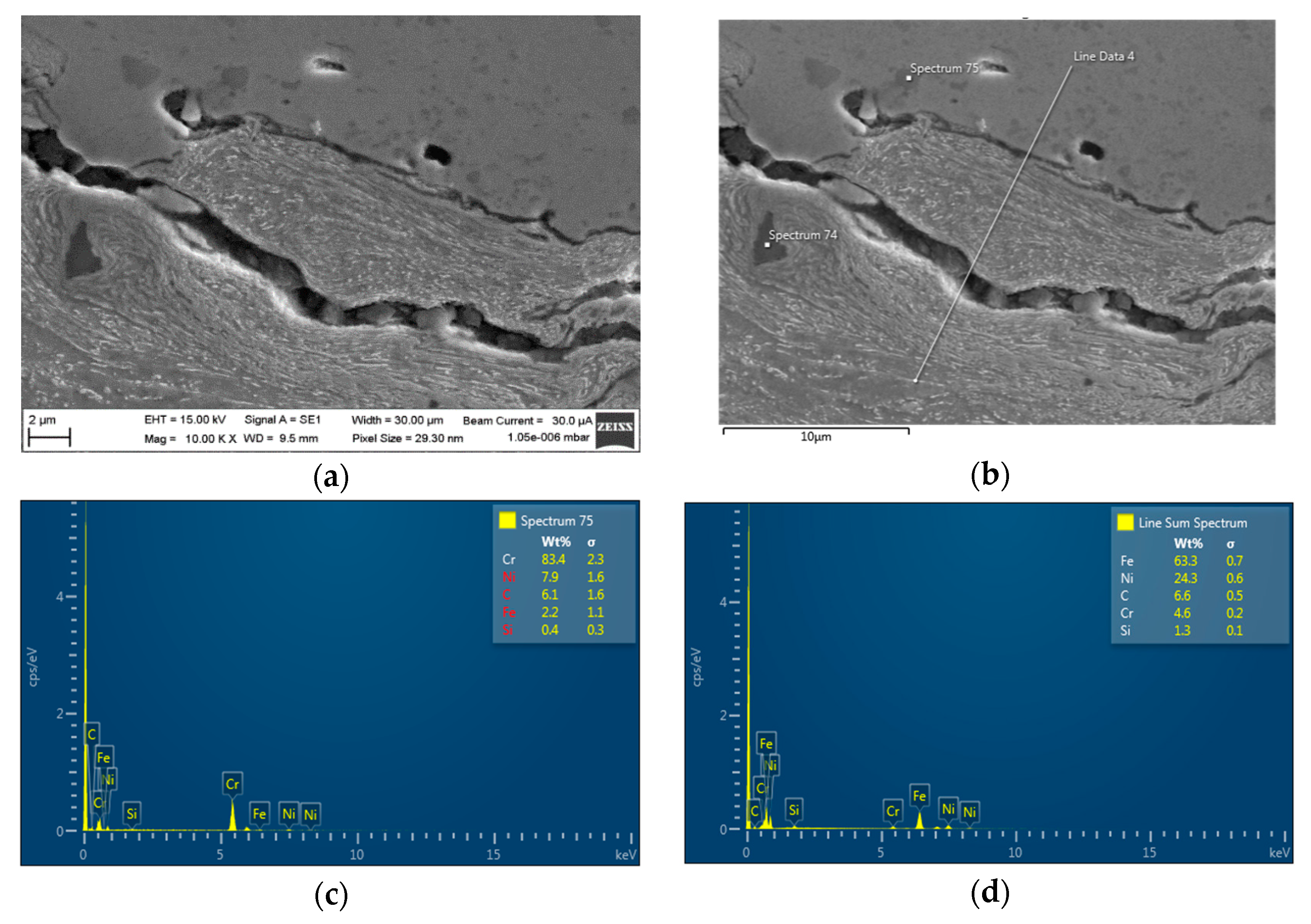
Figure 1 presents the morphological results of NiCrBSi powder spraying obtained by scanning electron microscopy (SEM, Semilab Germany GmbH, Braunschweig, Germany) (
Figure 1a,b) and analysis of this spraying by Energy dispersive X-Ray (EDX) technique (Bruker, Ewing, NJ, USA), commonly used in electron microscopy (
Figure 1c,d).
2.3. Milling the Surface of the Base Material after Spraying
The experiment is based on the results of direct measurements of three basic cutting parameters (
Table 3), namely: speed of cut
vc (m·min
−1), feed per tooth
fz (mm), and the depth of cut
ap (mm). The machining parameters mentioned above can be considered as technologically basic because they express the machined volume of material, the structure and texture of the machined surface, as well as its instantaneous stress-strain state. In addition to the final surface topography, they describe the stress-strain volume of the affected material at the contact of the cutting knife with the disintegrated material. The quality of homogenization of this transition determines the intensity of the adhesive stress and the action of the adhesive forces. The milling of the surface of the EN 10060 material after NiCrBSi spraying was performed on a linear milling centre DMU 40 eV olinear (DMU 40 eV olinear (DMG MORI, Pfronten, Bavaria, Germany). It is a new generation DMU eVo machine with a perfect interaction of the performance potential of the universal milling cutter and the vertical machining centre.
In order to examine the influence of the choice of cutting parameters, it can be stated that the combinations of selected parameters were selected arbitrarily and, to a large extent, subjectively, because even in current technical practice, there are still no relations of targeted, exactly continuous choice. The individual combinations of cutting parameters are listed in
Table 3 under
Section 2.3.
For the required depth of cut, workpiece width, tool diameter and the number of teeth, the recommended cutting conditions can be found commonly in machine tables, but only for machining relatively simple surfaces, most often planar. For complex surfaces, which spherical surfaces undoubtedly are, such optimization guidelines do not yet exist. Therefore, we applied an empirical approach when milling a specific coating, i.e., so that the machining of difficult-to-machine surfaces is feasible.
The experimental part of the paper is focused on investigating the influence of specifically defined combinations of cutting parameters in the machining of selected materials (NiCrBSi alloy and EN 100 60 metal). In the experiments, a total of 15 cuts were made by milling on a sprayed coating layer of NiCrBSi alloy.
The primary goal for milling the studied coating is to generate a homogeneous coating of constant thickness, with the desired adhesiveness, Vickers hardness, and surface roughness. However, the production process is not only about setting the optimal technological parameters (speed of cut, feed per tooth and depth of cut), but also about the efficient use of the cutting insert. The cutting insert edge must be changed because it heats up and wears out during milling. For this reason, 15 experiments on 15 spherical workpiece surfaces were divided into three groups, each consisting of 5 experiments, with just one cutting edge being used in one experiment.
For a group of experiments 1–5 of A section, optimal technological parameters were searched. At higher speeds of cut (above 500 m·min−1), the cutting edge even jammed, at lower speeds of cut (below 500 m·min−1) the surface was machined unevenly to a significant degree, so there were relatively deep irregularly spaced holes or larger hollows.
For a group of experiments 6–15, the optimally found speed of cut of 500 m·min−1 was used, and the remaining values of technological parameters were combined so that the feed per tooth and the depth of cut were measured in an empirically verified interval of 0.1 to 0.3 mm with a step of 0.05 mm. The relative machinability parameter Rmp showed an information value for the comparison of the results in terms of the necessary roughness and adhesive stress of the generated coatings. According to this newly introduced decision criterion, experiments 6–10 of B section were classified as the section with satisfactory surface roughness for the desired adhesion, and experiments 11–15 of C section were classified as the section with excellent surface roughness for the desired adhesion.
2.4. Measurement of Roughness and Vickers Hardness
The microtexture of the machined area was measured with an ALICONA non-contact-optical profilometer (Alicona Imaging GmbH, Raaba, Austria). A lens with 50× magnification was used to scan the planar and surface roughness of the surface.
The Vickers hardness of the machined area was measured after imprints using a Vickers hardness tester (M-400-A, LECO, St. Joseph, MI, USA), at a selected value of a loading force of 300 gf. The Vickers hardness value was calculated using the measured lengths of the imprint diagonals (the boundary lines located in the ocular were set to be located at the opposite corners of the imprint). The maximum accuracy of length measurement was 7 μm; specifically, in the case of steel 5 to 6 μm, in the case of NiCrBSi coating about 4 μm. Because the Vickers hardness varies depending on the cutting directions due to the characteristic anisotropy of the microstructure of thermal sprays, the Vickers hardness of the substrate and the spraying were measured on metallographic cuts perpendicular to the surface of the coatings.
The average Vickers hardness was calculated [
25,
26] for each sample according to Equation (1):
where
HV is the Vickers hardness,
F is the applied force (N), α is the mean angle between the opposite faces at the vertex of the pyramidal indenter (for the nominal angle α = 136°),
d is the arithmetic mean of the two diagonal lengths
d1 and
d2 (mm), and
g is the gravitational acceleration (m·s
−2) 9.807.
The distribution functions of selected cutting parameters for the calculation of the parameters Rmp and Rmp0 were related to the depth of cut ap.
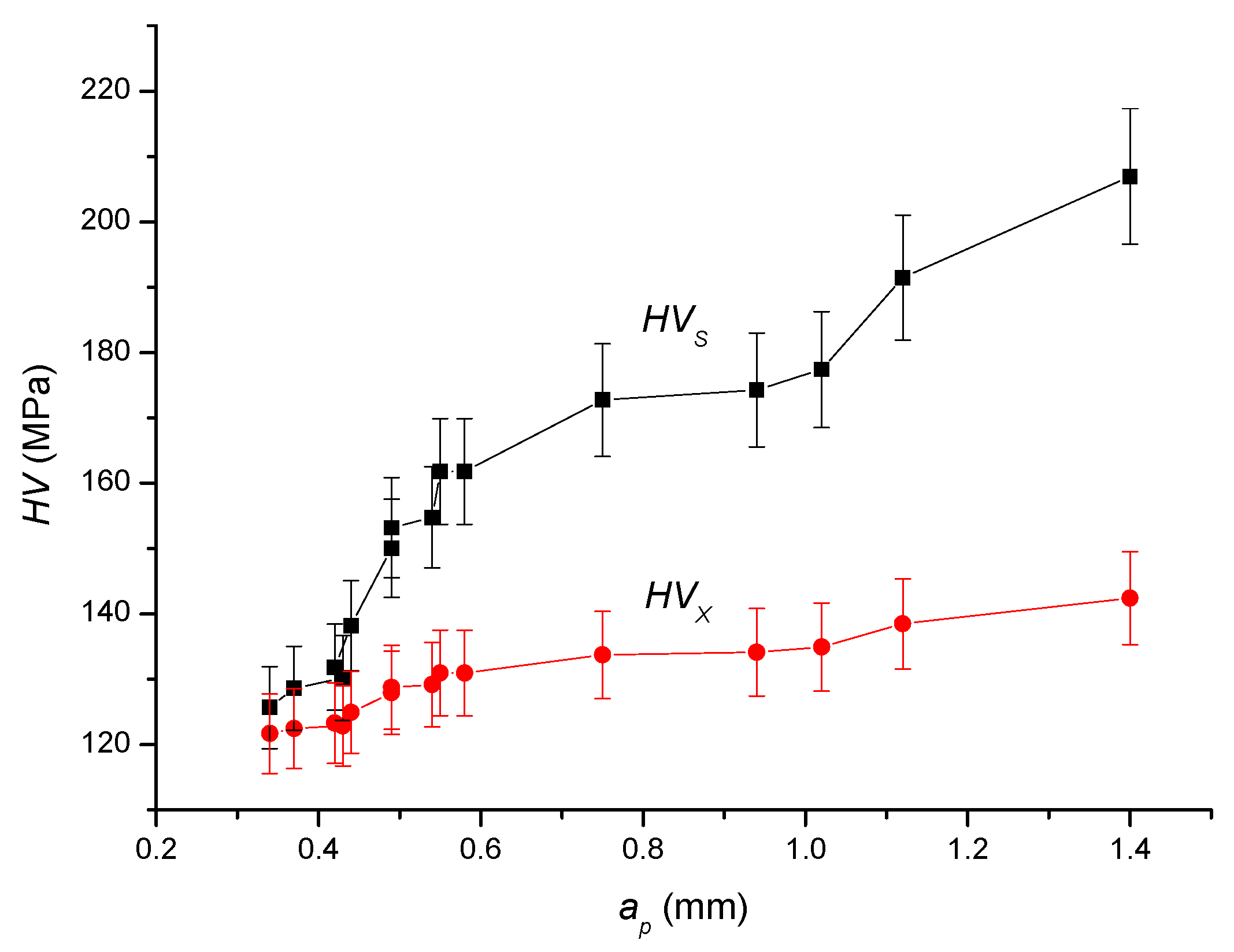
Figure 2 describes the dependence of the Vickers hardness of the substrate and the coating on the depth of cut, according to the approximation relations (2) and (3).
Equation (2) applies to substrate Vickers hardness and Equation (3) applies to spray Vickers hardness at a depth of cut with an accuracy of
R2 = 0.93:
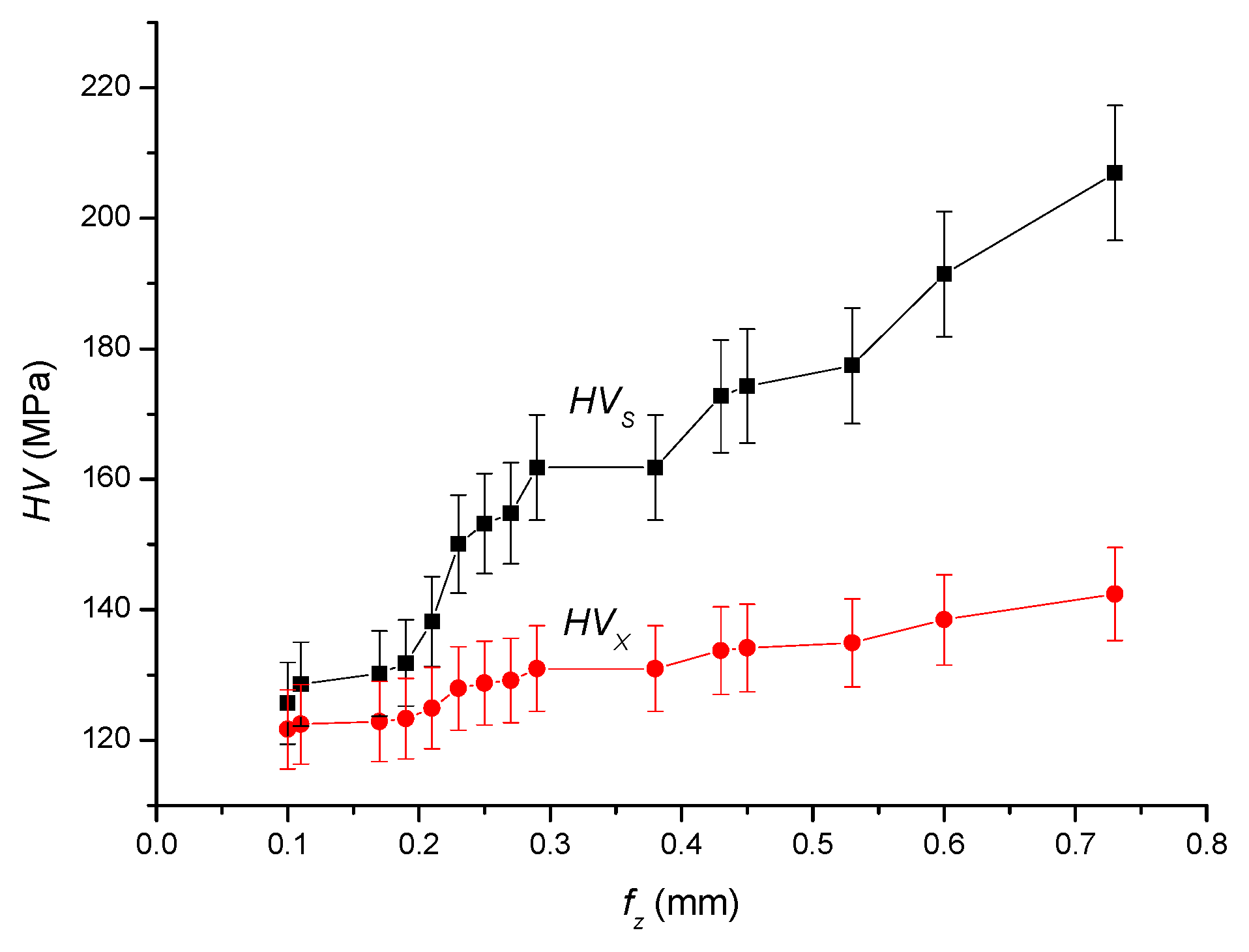
Figure 3 describes the dependence of the Vickers hardness of the substrate and the coating on the feed per tooth, according to the approximation relations (4) and (5).
Equation (4) applies to substrate Vickers hardness and Equation (5) applies to spray Vickers hardness at the feed per tooth with an accuracy of
R2 = 0.96:
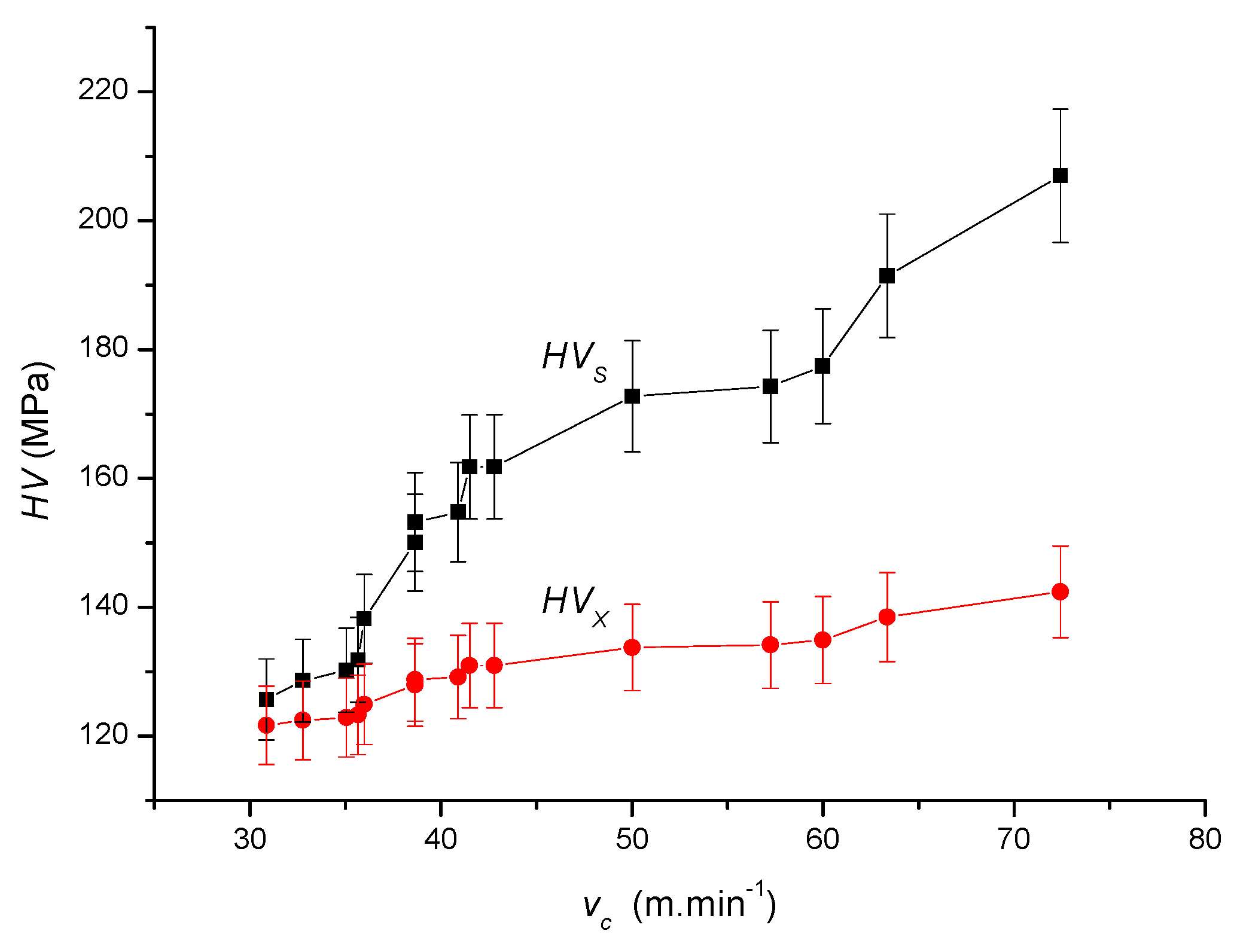
Figure 4 describes the dependence of substrate Vickers hardness and the coating on the speed of cut, according to the approximation relations (6) and (7).
Equation (6) applies for substrate Vickers hardness and Equation (7) applies to spray Vickers hardness on cutting speed with an accuracy of
R2 = 0.94:
3. Results and Discussion
3.1. Ratio of Machining Parameter
In the context of the relative parameter ratio of the machining parameter
Rmp (8), the following parameters were newly introduced: the ratio of the surface roughness machining parameter
(9), predicted surface roughness
(10), the ratio of the machining parameter to adhesion stress
(11), and finally adhesion stress
Adh (13). It is an integrated evaluation of the complex influence of cutting parameters on the mechanical state in the cut and, at the same time, also on the topographic state of the final surface after cutting.
In the case of , it is the ratio of the currently selected cutting parameters and the parameters calculated or graphically constructed for the neutral plane at a depth of cut on the neutral plane ap0. The parameters feed per tooth on the neutral plane fz0, speed of cut on the neutral plane vc0, the depth of cut on the neutral plane ap0, surface roughness on the neutral plane Ra0, and others are material parameters, i.e., and . These are ratios of currently selected values and values of given material parameters. Therefore, the derived parameters and can accurately express the instantaneous state of the mechanical tool−material interaction in the contact area, according to (9), (11). In principle, it is physically the ratio of the material cut to the volume of the theoretical material removal, precisely at the neutral depth of cut on the neutral plane ap0. The values of the ratio of the machining parameter on the neutral plane Rmp0 (in the area where the values of tensile and compressive stress are equal) must be calculated specifically for each material in conjunction with the neutral values vc0, fz0, ap0. However, the surface roughness on the neutral plane is the same for all materials: Ra0 = 3.70 μm. In the presented measurements, the following applies to the neutral plane of steel EN 10060: vc0 = 103.31 m·min−1, fz0 = 0.74 mm, ap0 = 0.22 mm.
The newly introduced parameters
Rmp and
integrate the complex influence of the set of selected cutting parameters on the mechanical state in the cut and, at the same time, also on the topographic state of the final surface after the cut. In the case of the parameter
RmpX (product of selected cutting parameters), it is the ratio of the currently selected cutting parameters and the parameters calculated or graphically constructed for the neutral plane
Rmp0 at a depth of cut on the neutral plane
ap0 (12).
The relative machining parameter related to the neutral plane, i.e., in the area where the values of tensile and compressive stress are equal, is Rmp0 = 1.
3.2. Adhesive Stress
For the newly presented relation (13) of a simple, discrete evaluation of the adhesive stress
Adh (based on the input technological parameters), an adequate relation (14) (based on the surface morphology) applies [
19]. This relation is based on simple mechanics, where it is a suitable/adequate ratio between the surface roughness of the machined substrate
Ra (µm) and the structural grain size
Dgr (µm) of the coating.
The values of the parameters in the relation (14) can be determined relatively simply and discretely:
Adh adhesive stress, i.e., the adhesive stress acting on the grain area of the coating [MPa],
Dgr size/diameter of the structural grain of the coating [µm],
EmSUB Young’s modulus of elasticity of the substrate material [MPa],
EmCOV Young’s modulus of elasticity of the coating material [MPa],
kpor degree of porosity of the coating according to the spraying technique [–].
By evaluating the relation (14), it is possible to express the adhesion on the neutral plane
h0, or in the depth of cut on the neutral plane
ap0, i.e., to express the user-desired adhesion between the substrate used (steel EN 100 60) and the coating used (nickel alloy NiCrBSi), at the value
kpor = 1 (15):
Therefore, adhesive stress
Adh0 on the neutral plane
h0, or in the depth of cut on the neutral plane
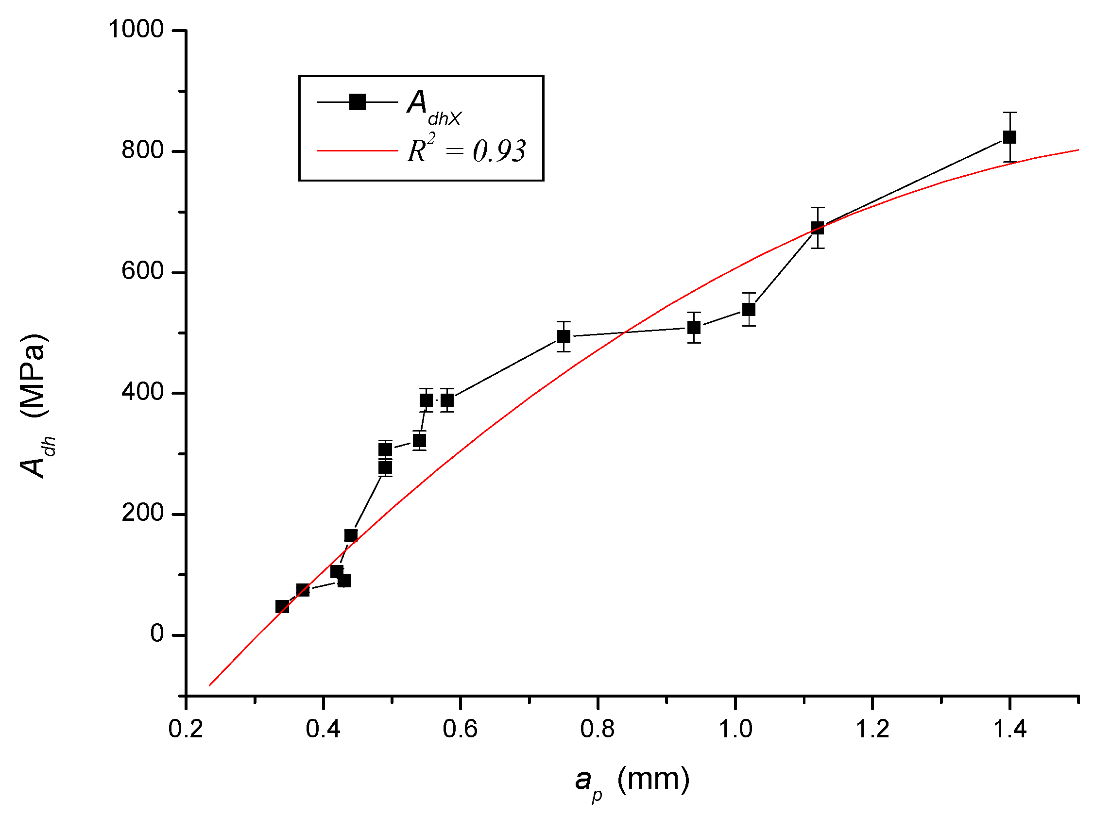
ap0, has a specific value of 401.4 MPa. The dependence of the adhesive stress
AdhX on the depth of cut is described in
Figure 5, according to the approximation relation (16), with excellent accuracy of measurement (0.93).
Now the solution can be assumed as follows:
(a) Utilizing other advantages of the newly derived parameter Rmp (mm3·min−1), it is possible to evaluate analogically and illustrate direct connections to specific cutting parameters, or to other parameters according to the presented implicit expression Adh = f·(fz, vc, ap…).
(b) Based on the above findings, the “adhesive potential of the substrate” can also be newly designed for the needs of applied research (17):
Based on such an accurately evaluated adhesion potential of the substrate, the most suitable coating material can be precisely selected from the point of view of the need to obtain solid adhesion. The adhesive potential of the substrate AdhS0 on the neutral plane h0, or in the depth of cut on the neutral plane ap0 after substituting the values of the subject parameters (kpor = 1, EmSUB = 347,050 MPa) into the relation (17) is 476.1 MPa. In conclusion, it can be stated that the specific value of the adhesive potential of the investigated substrate has a comparative information value from the point of view of industrial needs.
3.3. Comparison and Verification of Adhesion Measurement Results
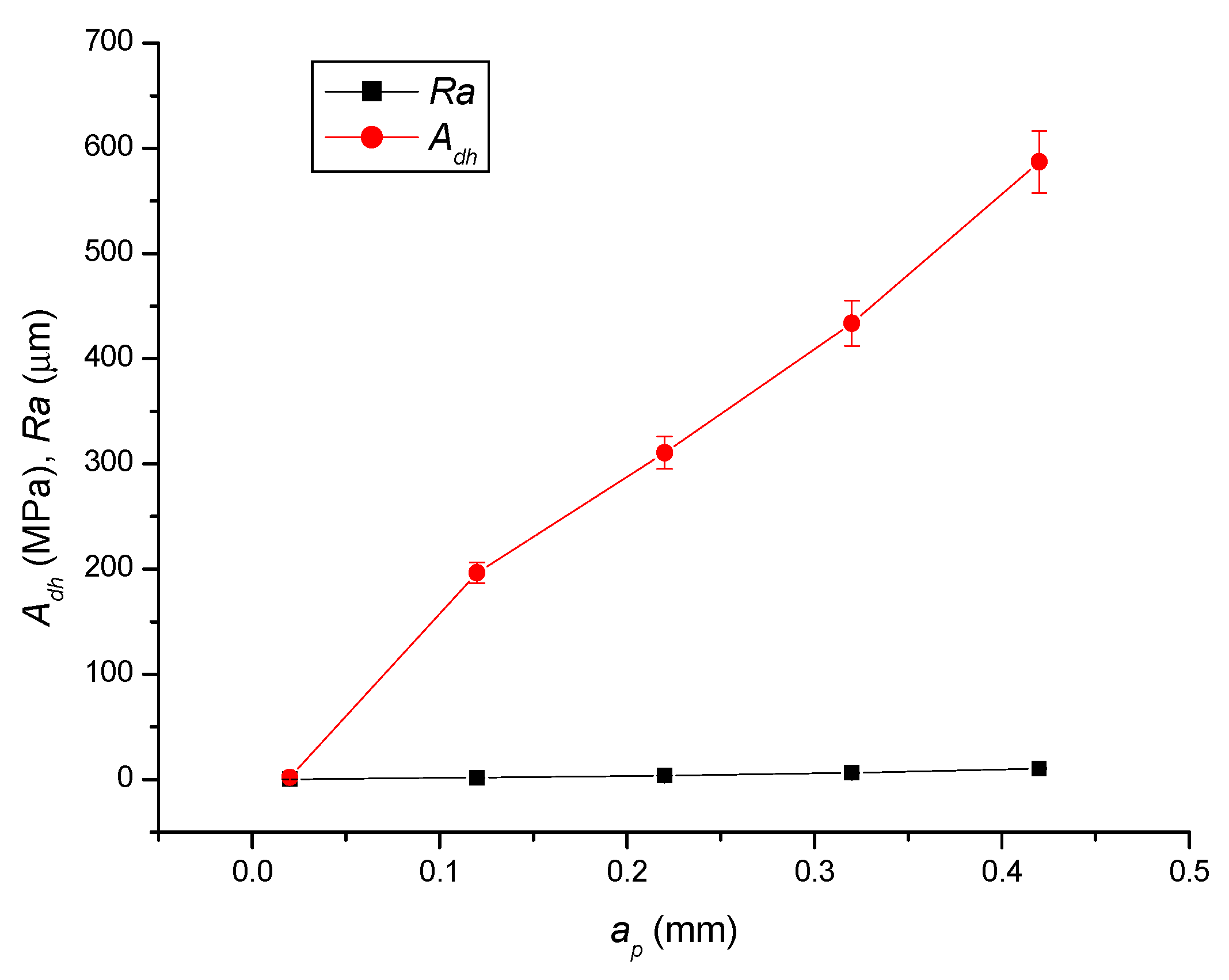
The calculated values of the adhesiveness
Adh and the corresponding measured surface roughness
Ra was given in relation to the measured depths of cut
ap. In particular, it can be seen from
Figure 6 that with the depth of cut, the surface adhesion increases relatively steeply, while the surface roughness of the coating is approximately constant. What plays an important role for the adhesion of the coating surface in the cut depth of a given depth is not only the roughness of the coating but also the roughness of the substrate, especially in the region of the depth of cut approaching the thickness of the coating. The adhesion of the coating surface has a specific comparative information value about the adhesion forces as attractive intermolecular chemical and physical forces in the irregularities and pores of the coating surface of the investigated material.
3.4. Vickers Hardness
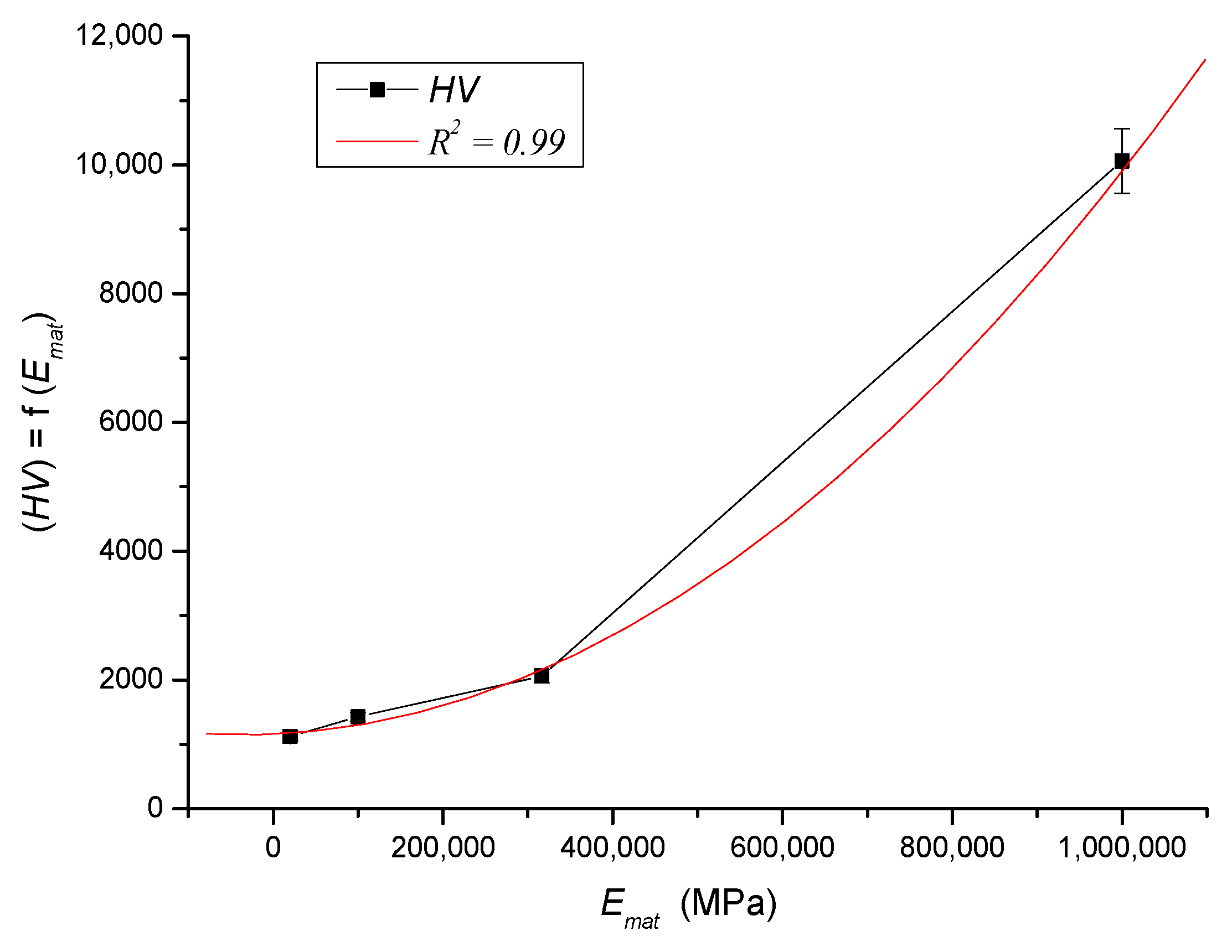
In connection with the measurement of Vickers hardness, reference can be made to the derivation of the approximation for the dependence of the Vickers hardness on Young’s modulus of elasticity
HV =
f·(
Emat). The obtained approximation (
Figure 7) is derived according to the Mohs hardness scale leading to the relation (18):
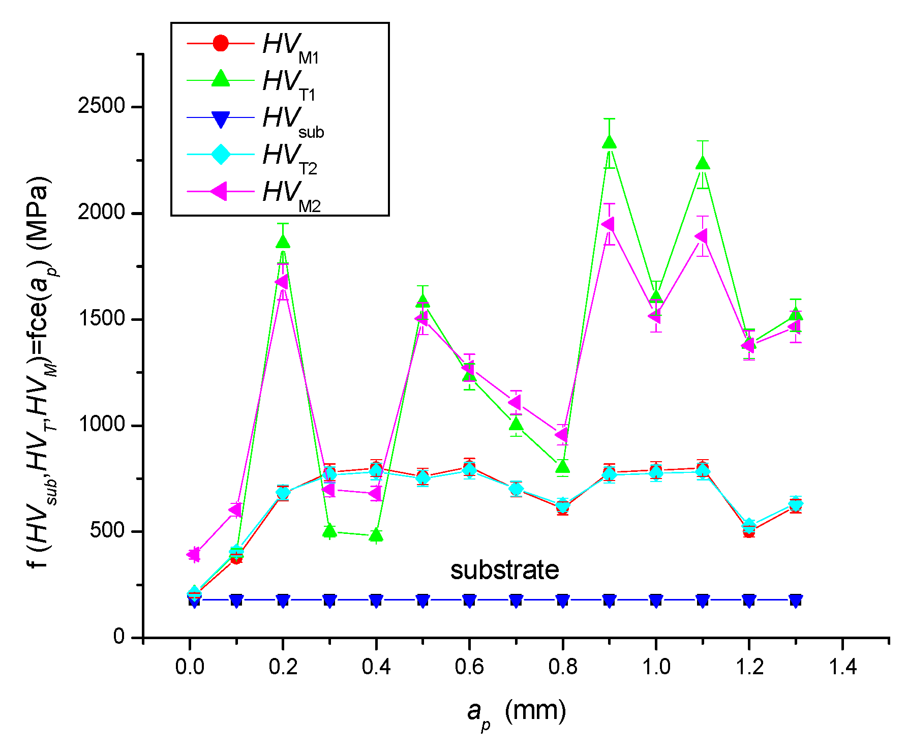
3.5. Comparison and Verification of Vickers Hardness Measurement Results
Comparisons and verifications of
HV Vickers hardness values were performed.
Table 4 shows the numerical comparison and verification of the obtained data and
Figure 8 shows their adequate graphical comparison, where the individual parameters are:
HVsub substrate Vickers hardness,
HVT theoretically calculated Vickers hardness according to Equation (18), and
HVM measured Vickers hardness.
3.6. Tensile Stress
Based on the relation (1), own measurement results, analyses and interpretations of obtained measurement results, a parameter characterizing tensile stress σ
rz can be introduced, which can be expressed by the relation (19) after modifications [
27,
28].
The parameter σ
rz can be expressed using the above parameter
Rmp, which is related to the technological parameters of milling, according to the relation (20):
where the relation (21) applies:
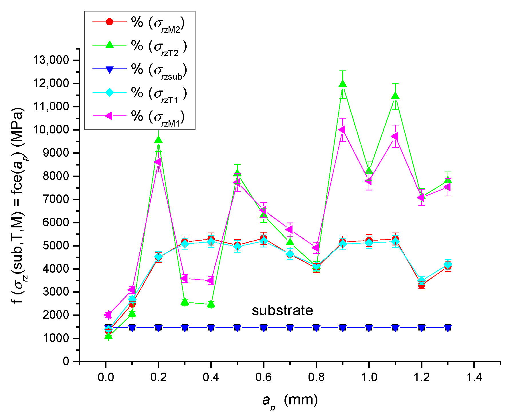
3.7. Comparison and Verification of Tensile Stress Measurement Results
Figure 9 presents a comparison of stress changes along with the depth of cut
ap of a steel substrate, NiCrBSi and NiCrBSi–WC coatings.
4. Interpretation of Data Using Adhesiveness and Relative Machining Parameter
Based on the measured data and their analysis, new prediction Equations (8)–(13) and (17) were created.
Table 5 illustratively shows the calculated values of
roughness,
Adh adhesion stress and
RmpX relative machining parameter, in the context of the measured
Rasub values
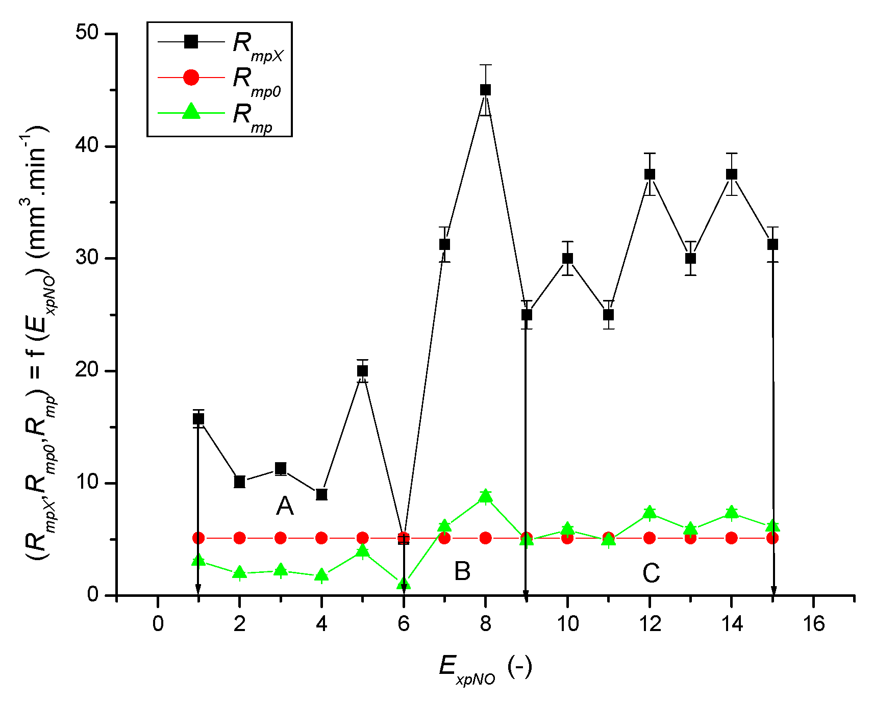
Based on the subject data analysis, classification into individual sections of adhesiveness was possible, based on the relative machining parameter
Rmp (
Figure 10):
section A (ExpNO 1–6) insufficient surface roughness for the required adhesion,
section B (ExpNO 7–9) suitable surface roughness for the required adhesion,
section C (ExpNO 10–15) excellent surface roughness for the required adhesion.
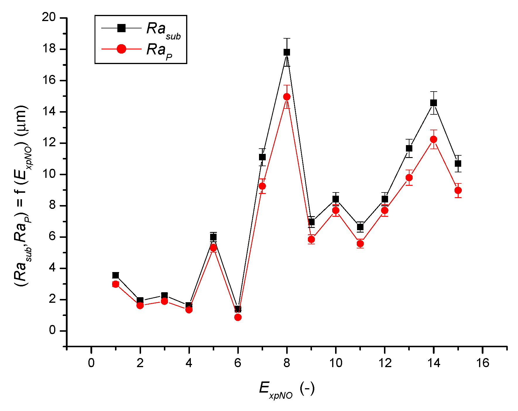
As an example of the calculation of surface roughness
Ra =
f·(
ExpNO) for EN 10060 substrate and spraying material NiCrBSi alloy to use the parameter
Rmp, a graph of the distribution of discrete values
Ra according to
Figure 11 can be presented, which depends on the direct relation to individual cutting parameters according to
Table 3, see also
Table 5. The calculation of the values of the graph in
Figure 11 was performed according to the above-declared relations (9) and (10).
The surface roughness parameter
Ra is a significant parameter for us and is also frequently used in our application calculations and in our newly derived relations. The importance of
Ra roughness for application calculations is elaborated in great detail in our patent specifications [
29,
30]. This article deals, for example, with the calculation of adhesion
Adh (14), with the applied calculation of roughness
=
f (
Rmp,
vc,
fz,
ap) (10), as well as with the calculation of surface stresses σ
rz =
f (
Ra,
Ra0,
Emat) (19). Equation (19) declares a new relation to the Vickers hardness
HV =
f (
Ra, σ
rz), which has been compared and verified with the literature [
29,
30], as presented in
Section 3.
The new relations mentioned above describing the relationships between technological, textural, stress-strain parameters and optimal parameters characterizing the milling technology (
ap, fz, vc) are based on the newly introduced parameter
Rmp, which is applied in various modifications, namely in relations (8) to (11), (13) and (21). Using this relative technological parameter
Rmp, it was also possible to reclassify the adhesive sections (
Figure 10).


 ,
, 


