Article

Microstructure and Wear-Resistant Properties of Ni80Al20-MoS2 Composite Coating on Sled Track Slippers

1
School of Aeronautics, Northwestern Polytechnical University, Xi’an 710072, China
2
China Aerospace Life-Support Industries, Ltd., Xiangyang 441003, China
*
Author to whom correspondence should be addressed.
Coatings 2020, 10(7), 651; https://doi.org/10.3390/coatings10070651
Submission received: 28 April 2020 / Revised: 10 June 2020 / Accepted: 10 June 2020 / Published: 6 July 2020
(This article belongs to the Section Corrosion, Wear and Erosion)

Abstract

:
In order to increase the surface hardness and wear-resistance property of sled track slippers, a Ni80Al20-MoS2 composite coating was fabricated on the surface of a stainless steel 0Cr18Ni9Ti sled track slipper via atmospheric spray and hot dipping. The microstructure, composition and surface hardness of coatings under different spraying powers were characterized and measured. The wear-resistant properties of the slipper substrate and the coating were also checked. The results showed that the higher the spraying power was, the greater the smoothness, density and hardness was of the Ni80Al20 coating, while the thickness initially increased and then decreased. When the spraying power was 18 kW, the thickness was 342.5 μm, the surface hardness was 304.1 Hv0.2, and the coating was composed of Ni, Al, Ni3Al, NiAl and a little Al2O3. The friction coefficient of the slipper substrate against GCr15 balls at room temperature in air was 0.7, while the coated substrate with MoS2 lubrication film was 0.3 and the volume wear rate declined by 1/5. The friction coefficient of the Ni80Al20 coating was 0.5 and the Ni80Al20-MoS2 composite coating was 0.15, while the volume wear rate declined by 1/4 and 1/3.

1. Introduction

The sled-track test system is a kind of ground testing facility which uses a sled rocket as the propulsion power to drive the sled running on a high-precision sled track under high velocities [1,2,3]. Studies on various aircraft moving under high velocities and high loads can be carried out by this facility. As the attachment between the sled and the track, the slippers must bear loads such as the rocket thrust, contact force, aerodynamic force and impact force during the sled track test, so they are always being worn because of the direct contact and relative movement to the track [4,5]. Therefore, the material for the track slipper must be highly wear-resistant and attrition-reducing. Research on the wear-resistant coating of the sled track slipper is rarely published, with only some publications on wear-out failure [6,7]. T.J. Watt found that during sled track testing, tiny cracks formed on the surfaces of the sled track and slippers first, and gradually became pits, eventually causing failures of the sled track and slippers [8]. M.J. Siopis considered that during high-speed rubbing, the wear surface of the slipper was almost molten, and the fusant functioned as the solid lubricant [9]. Wang Xiaohe studied the wear-out failure behaviors of slippers made, and the result indicated that the failure of the slippers was mainly caused by a heating effect generated by rubbing [10]. The author previously analyzed a frictional wear failure mechanism for 0Cr18Ni9Ti slippers under the supersonic speed of 938 m/s and a large payload of 850 kg, and found that under combined actions of payload and friction heat, typical wear such as abrasive wear, adhesive wear, oxidative wear, and fatigue wear coexisted on the surface of the slipper [11]. Given that failure caused by frictional wear on the surface of the material always leads to fatal damage to the workpiece, an attrition-reduction protective coating formed on the surface of the slipper is beneficial for improving the wear-resistant properties.
NiAl coating is a typical wear-resistant coating with a low density, high elastic modulus, high melting point and thermal conductivity, as well as excellent wear-resistant properties and oxidation resistance at high temperatures. M.C. Galetz researched the microstructural degradation and interdiffusion behavior of the NiAl coating on a 602 CA alloy, and the results showed that the coating was of structural integrity and highly protective [12]. O. Poliarus reported on NiAl coatings fabricated by the atmospheric plasma spray technique and its wear behavior [13]. Moreover, MoS2 can be used as a solid anti-attrition and lubricating coating because of its good self-lubricating and friction-reduction performances. L.R. Kumar studied the wear behavior of AA2219-MoS2 metal matrix composites in dry and lubricated conditions, and the results showed that its wear behavior was much lower [14]. M. Rouhi found that the introduction of MoS2 could improve the abrasion resistance of steel observably [15].
Therefore, in this paper, a Ni80Al20 coating is fabricated on a stainless steel 0Cr18Ni9Ti sled track slipper by atmospheric spray and then the microstructure and compositions, as well as the surface hardness of the coatings under different spraying power, are characterized and measured. After optimization of the spraying power, a coat of MoS2 lubrication film is covered on the Ni80Al20 coating by hot dipping. Ni80Al20 coatings under different spraying powers have been characterized and calculated for the friction coefficient, wear scar micromorphology, and wear rate. Tribological behavior of the Ni80Al20-MoS2 composite coating has been analyzed as well. The slipper material employed in this study is commonly used by Chinese sled track testing bases, so the results are reliable to the studies on slipper attrition reduction and are of great significance to increasing the sled test velocities and meeting the test requirements.

2. Test Materials and Research Methods

2.1. Test Materials

In this paper, stainless steel 0Cr18Ni9Ti was chosen as the material of the slipper substrate, of which the elements and contents are shown in Table 1. All samples were machined into a size of 30 mm × 20 mm × 10 mm by electro-discharge machining. Al coated Ni powder type KF-2, in which the nominal contents of Ni and Al are 80% and 20%, respectively, was used as the powder of the atmospheric spray. Figure 1 shows the micromorphology of the Ni80Al20 alloy powder, and Figure 2 shows the XRD test spectrum for the powder.
As shown in Figure 1a, the Ni80Al20 powder was composed of well-dispersed and even particles, of which the diameter was 30–50 μm. Figure 1b and Figure 2 show the partially enlarged details of powder particles and the element analysis results of EDS, respectively. It can be deduced from the pictures that the Al cores were wrapped and covered by the Ni coating layer. The content of Ni atoms in the Ni coating layer was 97.5% and that of Al atoms in Al cores was 95.9%, by EDS quantitative analysis.
An XRD test was conducted on the Ni80Al20 alloy powder, and the result is shown in Figure 3. It can be deduced from the XRD test spectrum that the Ni80Al20 alloy powder was composed of crystalline Ni and Al. In order to keep the alloy powder well-dispersed and dry, before spraying, it should be placed under atmosphere environment with a temperature of 200 °C to air dry for 2 h.

2.2. Coating Preparation

Before atmospheric spray, the slipper substrate should be sandblasted to improve the bonding strength between the coating and substrate material. In this paper, we sandblasted the substrate at a distance of 20 cm, an angle of 50°, and a pressure of 1.0 MPa. The blasting time was 10 min and the surface roughness of the blasted substrate was about 15.6 μm, and then the surface was pre-heated to above 200 °C.
The Ni80Al20 coating was made with XM-80SK atmospheric spray equipment (Shanghai Xiuma Spraying Machinery Co., Ltd., Shanghai, China). The distance for spraying was 10 cm. Take Ar with a flow of 3000 L/h as the main gas, H2 with a flow of 300 L/h as the shielding gas and N2 with a flow of 500 L/h as the powder feeding gas. The spraying current was 300 A, with the voltages set to 40, 50, and 60 V in turn, corresponding to the spraying powers, and the spraying time was 5 min. We placed the sprayed slipper samples in the MoS2-polysilane organic dispersant for 30 min and then dried it under atmospheric conditions at a temperature of 220 °C for 2 h. Consequently, the MoS2 film of 10 μm was formed on the surface of the Ni80Al20 coating.

2.3. Coating Characteristics and Property Testing

Several tests have been conducted on the Ni80Al20 alloy powder and different Ni80Al20 coatings: firstly, micromorphology and chemical compositions and contents were characterized by FESEM (Verios G4, FEI, Thermo Fisher Scientific, Waltham, MA, USA) and matching EDS; secondly, phase composition was analyzed by XRD (XRD-7000, Shinadzu, Kyoto, Japan). We used a Cu target with a scanning angle of 20°–80° (2θ) and scanning precision of ±0.0001° (θ). Then, surface hardness of the slipper substrate and coatings was measured with Vickers. Roughness of all samples was tested by the surface roughness measuring instrument. Ball-on-disc friction tests with a GCr15 ball for the slipper substrate, slipper with MoS2 lubrication film, with Ni80Al20 coating sprayed under 18 kW, and Ni80Al20-MoS2 composite coating, were carried out under atmosphere conditions with a HT-1000 high-temperature frictional wear tester (Lanzhou Huahui Instrument Technology Co., LTD., Lanzhou, China). As shown in Figure 4, GCr15 balls acted as friction pairs and grinded with the surface of coated samples, while the load was 10 N, the rotation rate was 224 r/min, the diameter was 10 mm and the duration was 30 min. Lastly, the surface profiles of the wear scars were measured by a TR300 profilometer and the volume abrasion rate was calculated based on it.

3. Test Results and Analysis

3.1. Microstructure, Compositions and Hardness of Ni80Al20 Coating

Figure 5 shows different Ni80Al20 coating micromorphologies formed under different spraying powers. From Figure 5a, it can be seen that when the spraying power is 12 kW, the coating is smooth with some depressions and prominences, and there are lots of unmelted powder particles. From Figure 5b, it is found that the uniform coating has an average thickness of 187.5 μm, and the surface roughness was 5.4 μm. There are many micropores in the sectional structure and small holes at the bonding interface between the coating and the substrate. It is the combined effect of the low spraying power, low ion beam energy and low temperature [13]. The powder particles are not melted at all or are only melted on the surface, so the fusant has bad fluidity [16], which causes a rough surface and loose micro-structure. When spraying on the surface of the substrate sample, the unmelted powder particles present staggered accumulation, which results in an uncompacted microstructure with an abundance of micropores and poor bonding strength between the coating and the substrate. When the spraying power is increased to 15 kW, the coating becomes smoother and thicker, of which the average thickness is 423.0 μm, and the surface roughness is 4.1 μm. Although the depressions and prominences are fewer, and the unmelted powder particles are decreased, plenty of micropores still exist, and porosity of the coating drops from 16% in Figure 5b to 13% in Figure 5d, as shown in Figure 5c,d. This indicates that the ion beam energy is increasing with the increase of the spraying power [13,17]. Under this condition, the fully melted particles, flying at a high speed, impact the surface of the substrate and spread along it, forming a thicker coating. When the spraying power is 18 kW, the coating can be even smoother with few unmelted particles, as shown in Figure 5e. The average thickness was 342.5 μm, the surface roughness was 2.6 μm and the porosity of the coating was 11%, which is lower than that under 15 kW. However, the bonding strength with the substrate is higher. As shown in Figure 5f, there were fewer micro-pores and micro-cracks in the cross-sectional structure, especially at the interface, and it could be concluded that the bonding strength was improved. The literature indicates that the NiAl alloy is a kind of typical exothermic, self-adherent composite material. An exothermic reaction will happen between melted Al and Ni when the spraying power is high enough. Both the density and bonding strength will be improved because the heat released during the reaction heats and melts the coating again [18].
Figure 6 shows the SEM backscattering result and section-distribution result of the elements for the coating section in Figure 6f, and Table 2 displays the EDS analysis of different areas in Figure 6a. There are three different microstructures in the coating section, as shown in Figure 6a. It can be concluded, according to the distribution of Ni and Al in Figure 6b,c, that the light white area in Figure 6a is a Ni rich origination, the grey area is a Ni-Al alloy organization, while the dark color area is an Al rich organization. That means during spraying, a combination reaction happened between Ni and Al.
Figure 7 shows the XRD testing results for Ni80Al20 coating surfaces under different spraying powers. It can be found that, when the power is 12 kW, the coating is formed by a Ni phase, Al phase and some NiAl and Ni3Al phases. When the power is increased to 15 kW, the intensity of diffraction and the absorption peak for NiAl and Ni3Al phases increases as well, which means the relative amount of these two phases is added in the coating. When the power is 18 kW, a new diffraction and absorption peak of Al2O3 occurs in the coating, which means that during the atmospheric spray, some Al is oxidized into Al2O3 by O2 in the air [19].
The Vickers hardness curve of the slipper substrate and Ni80Al20 coating surfaces formed under different spraying powers is shown in Figure 8. It can be seen that the surface hardness of the slipper substrate is about 197.0 Hv0.2, which is lower than that of the coating (246.6 Hv0.2) under a spraying power of 12 kW. When the power increases to 15 kW, the average hardness of the coating increases to 254.9 Hv0.2, which benefits from the increase of NiAl and Ni3Al phases in the coating, analyzed according to the XRD spectrum. Correspondingly, the average hardness increases significantly to 304.1 Hv0.2 under the spraying power of 18 kW; the reasons for this are that NiAl and Ni3Al phases in the coating increase on one hand, and on the other hand, the Al2O3 hard phase appears in the coating.

3.2. Wear-Resistant Properties for Various Samples

The friction coefficient curses of samples are shown in Figure 9. When rubbing with a GCr15 ball, the running-in period of the slipper substrate is so short that its friction coefficient is 0.7 after rubbing for 30 min, while with a MoS2 lubrication film, the coefficient is reduced to 0.3, which means MoS2 particles function as a kind of lubricant to the slipper substrate. For the Ni80Al20 coating, the friction coefficient changes from increased to decreased; that is, the coefficient is 0.7 when rubbing for 5 min, and then lowers to 0.5 after another 25 min. It is lower than that of the substrate, indicating the Ni80Al20 coating with greater hardness will reduce the friction coefficient of the substrate [20]. Comparably, the coefficient of the Ni80Al20-MoS2 composite coating is 0.15, implying that the MoS2 film lubricates the Ni80Al20 coating significantly.
Figure 10 shows the micromorphology of wear scars on different samples rubbing against the GCr15 ball for 30 min. As shown in Figure 10a, along the rubbing direction, the substrate wear scars present different micromorphologies on the internal and external sides. Local fractures and peel-off on the internal side indicate that fatigue wear occurs, causing plastic deformation on the substrate surface, while adhesive pits on the external side imply adhesive wear [21,22]. Some pits and spots on the external side of wear scars imply abrasive wear, since the debris generated during rubbing adheres on the wear surface to function as abrasive particles. It can be found in Figure 10b that the wear scars on the Ni80Al20 coating surface are mainly broken and peeled-off flakes, which is evidence of fatigue wear on the surface of the coating.
As shown in Figure 10c,d, abrasive wear mainly occurs in the MoS2 lubrication film. An EDS energy spectrum test on the abrasive particles in the scars is carried out, and the result shows the elements in the particles are mainly composed of Mo and S, since MoS2 particles are the majorities in the abrasive particles. It is assumed that during rubbing, the MoS2 lubrication film is cut and crushed into MoS2 particles on the surface of the friction pair, and a new stronger and smoother protective coating is formed on the abrasive surface by MoS2 particles. The thin flake of crushed MoS2 particles adheres to the friction surface to function as a solid lubricant [14,15]. So that direct contact between the sample and the friction pair is minimized, the friction coefficient is reduced greatly and the wear on the surface of the friction pair is less [23]. Meanwhile, the MoS2 particle size in the wear scars of the MoS2 lubrication film covering the surface of the substrate is larger, while for the MoS2 lubrication film on the Ni80Al20 coating, there is a neat gap at the edge of the wear scar, meaning good bonding strength and a synergistic effect between MoS2 and the NiAl alloy [24].
The profiles and volume abrasion rates of different samples are shown in Figure 11 and Figure 12. As shown in Figure 11, the scar profiles of both the slipper substrate and the Ni80Al20 coating present an approximate “V” shape. However, the depth and width of the substrate scars are larger than those of the Ni80Al20 coating scars. The predicted volume abrasion rate of the Ni80Al20 coating is 3.62 (10−6 mm−3·N−1·m−1); compared with 4.85 (10−6 mm−3·N−1·m−1) of the substrate, it is lowered by about 1/4. As the friction pair, the GCr15 ball has a greater hardness of 750 Hv0.2, so V-shaped scars are made on the substrate and Ni80Al20 coating during rubbing against it. However, the hardness of the Ni80Al20 coating composed of NiAl, Ni3Al and Al2O3 phases is greater than that of the substrate, which results in a lower friction coefficient and volume abrasion rate because of less cutting during rubbing with the GCr15 ball. After coating with the MoS2 lubrication film, the scar profile of the sample presents a “U” shape, with a little more depth and width of the scar than those of the Ni80Al20 coating. The mean volume abrasion rates of the slipper substrate covered with MoS2 film and Ni80Al20-MoS2 composite coating are 4.06 (10−6 mm−3·N−1·m−1) and 3.23 (10−6 mm−3·N−1·m−1), respectively, which is lowered by 1/5 and 1/3 compared with that of the bare substrate. It should be noted that, after covering the MoS2 film, both the profiles of the wear scars and the volume abrasion rates are calculated based on the reference of the thickness of the film. As shown in Figure 10, with the EDS element test for wear scars, MoS2 particles are the majority in the abrasive particles, indicating no wear or tiny wear to the substrate and coating during rubbing. Moreover, the friction coefficients of the slipper substrate and the Ni80Al20 coating in Figure 9 were undulating, while the friction coefficients of the substrate with MoS2 film and the Ni80Al20-MoS2 composite coating were much smoother. As in conjunction with Figure 10 and Figure 11, the MoS2 lubrication film lubricated the wear behavior and caused the smooth friction coefficients and U-shaped scars.

4. Conclusions

  • The higher the spraying power is, the greater the smoothness, density and hardness are for the Ni80Al20 coating, while the thickness changes from increased to decreased. When the spraying power is 18 kW, the thickness of the coating made up of Ni, Al, Ni3Al, NiAl and a little Al2O3 is 342.5 μm, with a surface hardness of 304.1 Hv0.2.
  • When rubbing with a GCr15 ball under normal temperature, the friction coefficient of the slipper substrate is 0.7, which decreased to 0.3 after being coated with the MoS2 lubrication film, and the volume abrasion rate is cut down by about 1/5. The friction coefficient of the slipper with Ni80Al20 coating is 0.5 and with Ni80Al20-MoS2 composite coating is 0.15, comparatively. The volume abrasion rate decreases by about 1/4 and 1/3, respectively, with these two kinds of coating, compared to the bare slipper substrate.
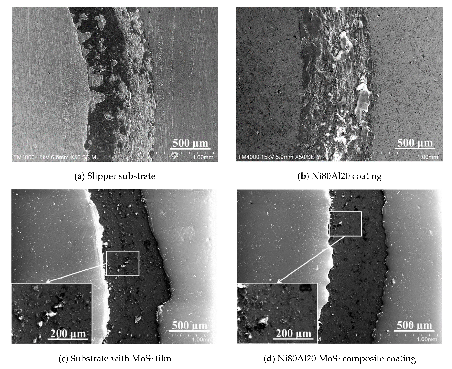
  • Abrasive wear mainly occurs on the slipper sample covered with the MoS2 lubrication film. The particles generated by a crushed MoS2 film lubricate the friction surface so as to reduce the friction coefficient and volume abrasion rate effectively. Moreover, the MoS2 lubrication film lubricates the wear behavior and causes smoother friction coefficients and U-shaped scars of the substrate with the MoS2 film and the Ni80Al20-MoS2 composite coating.

Author Contributions

W.W., Methodology, Investigation, Data curation. F.X., Writing—original draft, Writing—review & editing. X.W., Conceptualization, Validation, Formal analysis. Z.Z., Supervision. S.W., Validation, Formal analysis, Investigation, Resources, Data curation. T.L., Writing—review & editing. All authors have read and agreed to the published version of the manuscript.

Funding

This work was financially supported by The Science and Technology Program for Research and Development of Shaanxi Province (2018JZ5004).

Conflicts of Interest

The authors declare no conflict of interest.

References

  1. Cameron, G.; Palazotto, A. An evaluation of high velocity wear. Wear 2008, 265, 1066–1075. [Google Scholar] [CrossRef]
  2. Wuertemberger, L.; Palazotto, A.N. Evaluation of flow and failure properties of treated 4130 steel. J. Dyn. Behav. Mater. 2016, 2, 207–222. [Google Scholar] [CrossRef] [Green Version]
  3. Chmiel, A.J. Finite Element Simulation Methods for Dry Sliding Wear. Available online: https://pdfs.semanticscholar.org/6363/d1d178f628b5bcf181997afd02552a69d0b7.pdf (accessed on 28 April 2020).
  4. Burton, C.A. A Finite Element Study of Sliding Friction between Rough Surfaces. 2009. Available online: https://ecommons.udayton.edu/cgi/viewcontent.cgi?article=2855&context=graduate_theses (accessed on 28 April 2020).
  5. Burton Chad, A.; Brockman Robert, A. Frictional Interactions in High speed Sliding Contact. In Proceedings of the 50th AIAA/ASME/ASCE/AHS/ASC Structures, Structural Dynamics and Materials Conference, Palm Springs, CA, USA, 4–7 May 2009. [Google Scholar]
  6. Hale Chad, S. Consideration of Wear Rates at High Velocities, AFIT/DS/ENY/10-08. Ph.D. Thesis, Air Force Institute of Technology, Wright Patterson AFB, Greene County, OH, USA, 2009. [Google Scholar]
  7. Cinnamon John, D.; Palazotto Anthony, N. Analysis and simulation of hypervelocity gouging impacts for a high speed sled test. Int. J. Impact Eng. 2009, 36, 254–262. [Google Scholar] [CrossRef]
  8. Watt, T.J.; Clay, C.E.; Bassett, P.M.; Bourell, D.L. The effect of surface indentations on gouging in railguns. Wear 2014, 310, 41–50. [Google Scholar] [CrossRef]
  9. Siopis, M.J.; Neu, R.W. The effect of tribomaterial pairings on wear of an aluminum slider under high sliding speeds and high contact pressure. Wear 2016, 352, 180–187. [Google Scholar] [CrossRef] [Green Version]
  10. Wang, X.-H.; Liu, B.; Xiao, J. Investigation on friction and wear topography features and failure mechanism of slide of rocket sled. Surf. Technol. 2019, 3, 141–148. (In Chinese) [Google Scholar]
  11. Wang, W.-H.; Xie, F.-Q.; Wu, X.-Q.; Wang, S.-Q.; Lv, T. Investigation on Friction and Wear Failure Mechanism of Rocket Sled Slide at Supersonic and under High Load. Cailiao Daobao 2020, 8. in press (In Chinese) [Google Scholar]
  12. Galetz, M.C.; Oskay, C.; Madloch, S. Microstructural degradation and interdiffusion behavior of NiAl and Ge-modified NiAl coatings deposited on Alloy 602 CA. Surf. Coat. Technol. 2019, 364, 211–217. [Google Scholar] [CrossRef]
  13. Poliarus, O.; Morgiel, J.; Umanskyi, O.; Pomorska, M.; Bobrowski, P.; Szczerba, M.; Kostenko, O. Microstructure and wear of thermal sprayed composite NiAl-based coatings. Arch. Civ. Mech. Eng. 2019, 19, 1095–1103. [Google Scholar] [CrossRef]
  14. Kumar, L.R.; Saravanakumara, A.; Bhuvaneswari, V.; Gokul, G.; Kumar, D.D.; Karunan, M.J. Optimization of wear behaviour for AA2219-MoS2 metal matrix composites in dry and lubricated condition. Mater. Today 2019, in press. [Google Scholar]
  15. Rouhi, M.; Goundarzi, M.M.; Ardestani, M. Comparison of effect of SiC and MoS2 on wear behavior of Al matrix composites. Trans. Nonferrous Met. Soc. China 2019, 29, 1169–1183. [Google Scholar] [CrossRef]
  16. Gao, Y.-L.; Jie, M.; Liu, Y. Mechanical properties of Al2O3 ceramic coatings prepared by plasma spraying on magnesium alloy. Surf. Coat. Technol. 2017, 315, 214–219. [Google Scholar] [CrossRef]
  17. Deng, W.; Li, S.; Hou, G.; Liu, X.; Zhao, X.; An, Y.; Zhou, H.; Chen, J. Comparative study on wear behavior of plasma sprayed Al2O3 coatings sliding against different counterparts. Ceram. Int. 2017, 43, 6976–6986. [Google Scholar] [CrossRef]
  18. Bolelli, G.; Cannillo, V.; Lusvarghi, L.; Manfredini, T. Wear behaviour of thermally sprayed ceramic oxide coatings. Wear 2006, 261, 1298–1315. [Google Scholar] [CrossRef]
  19. Tian, W.; Wang, Y.; Zhang, T.; Yang, Y. Sliding wear and electrochemical corrosion behavior of plasma sprayed nanocomposite Al2O3-13%TiO2 coatings. Mater. Chem. Phys. 2009, 118, 37–45. [Google Scholar] [CrossRef]
  20. Yılmaz, Ş. An evaluation of plasma-sprayed coatings based on Al2O3 and Al2O3-13wt.% TiO2 with bond coat on pure titanium substrate. Ceram. Int. 2009, 35, 2017–2022. [Google Scholar] [CrossRef]
  21. Wang, S.-Q.; Xie, F.-Q.; Wu, X.-Q.; Ma, Y.; Du, H.-X.; Wu, G. Cathodic Plasma Electrolytic Deposition of ZrO2/YSZ Doped Al2O3 Ceramic Coating on TiAl Alloy. Ceram. Int. 2019, 45, 18899–18907. [Google Scholar] [CrossRef]
  22. Wang, S.-Q.; Xie, F.-Q.; Wu, X.-Q.; Lv, T.; Ma, Y. Microstructure and high temperature oxidation behavior of the Al2O3 CPED coating on γ-TiAl alloy. J. Alloys Compd. 2020, 828, 154271. [Google Scholar] [CrossRef]
  23. Mahathanabodee, S.; Palathai, T.; Raadnui, S.; Tongsri, R.; Sombatsompop, N. Dry sliding wear behavior of SS316L composites containing h-BN and MoS2 solid lubricants. Wear 2014, 316, 37–42. [Google Scholar] [CrossRef]
  24. Holbery, J.; Pflueger, E.; Savan, A.; Gerbig, Y.; Luo, Q.; Lewis, D.; Münz, W.-D. Alloying MoS2, with Al and Au: Structure and Tribological Performance. Surf. Coat. Technol. 2003, 169, 716–720. [Google Scholar] [CrossRef]
Figure 1. Micromorphology (a) and partially enlarged details (b) of Ni80Al20 alloy powder.
Coatings 10 00651 g001
Figure 2. EDS element contents analysis for different parts (a) Point A and (b) Point B in Figure 1b.
Coatings 10 00651 g002
Figure 3. XRD spectrum of Ni80Al20 alloy powder.
Coatings 10 00651 g003
Figure 4. The diagram of the measuring station for abrasion.
Coatings 10 00651 g004
Figure 5. Micromorphology of Ni80Al20 coatings formed under different spraying powers: (a) Surface-12 kW, (b) Cross-sectional-12 kW, (c) Surface-15 kW, (d) Cross-sectional-15 kW, (e) Surface-18 kW and (f) Cross-sectional-18 kW.
Coatings 10 00651 g005aCoatings 10 00651 g005b
Figure 6. Backscattering result (a) and section-distribution result for elements: (b) Ni and (c) Al for Figure 4f.
Coatings 10 00651 g006aCoatings 10 00651 g006b
Figure 7. XRD spectrum of Ni80Al20 coatings under different spraying powers.
Coatings 10 00651 g007
Figure 8. Surface hardness of slipper substrate and coatings under different spraying powers.
Coatings 10 00651 g008
Figure 9. Friction coefficients of slipper substrate and different coatings: S, Slipper substrate, C, Ni80Al20 coating, S + M, Substrate with MoS2 film and C + M, Ni80Al20-MoS2 composite coating.
Coatings 10 00651 g009
Figure 10. Micromorphology of wear scars on samples rubbing with GCr15 ball, (a) Slipper substrate, (b) Ni80Al20 coating, (c) Substrate with MoS2 film and (d) Ni80Al20-MoS2 composite coating.
Coatings 10 00651 g010
Figure 11. Measurement results for different wear scar profiles: S, Slipper substrate, C, Ni80Al20 coating, S + M, Substrate with MoS2 film and C + M, Ni80Al20-MoS2 composite coating.
Coatings 10 00651 g011
Figure 12. Predicted results of volume abrasion rate of various samples: S, Slipper substrate, C, Ni80Al20 coating, S + M, Substrate with MoS2 film and C + M, Ni80Al20-MoS2 composite coating.
Coatings 10 00651 g012
Table 1. Material elements and contents of stainless steel 0Cr18Ni9Ti slipper (wt.%).
ElementsCSiMnPSNiCrTiFe
Contents≤0.07≤1.00≤2.00≤0.035≤0.0308–1117–195Cremainder
Table 2. EDS analysis of different areas in Figure 6a.
AreasContent (at.%)Error (at.%)
NiAlNiAl
Ni-rich area89.310.76.81.2
Al-rich area65.934.14.64.1
Ni-Al area81.619.45.61.5

