1. Introduction
The industrial manufacturing process predominantly used for contact materials made of Ag–W is the impregnation of sintered porous tungsten bodies infiltrated with liquid silver. The combination of Ag and W connects the thermal and electrical conductivity of Ag with the burn-off resistance of the high-melting W. On the typical industrial scale, these materials with a W content from
= 50%–80% are produced by powder metallurgy as solid impregnation material by sintering [
1]. In electrical contacts, these materials are used as burn-off contacts for circuit breakers and as contacts for molded case circuit breakers. They are also used in high current contactors where resistance to contact welding and arc erosion are required. When used as power electronics for the automotive industry, however, the production costs of the components are of critical importance. This means that a significantly cheaper electroplating process of a thin layer is preferable to the powder metallurgical manufacturing process of a solid component. Moreover, since the sintered materials consist of 2-phase systems due to the immiscibility of Ag and W, the electrodeposition of an alloy or a comparable layer would be equally advantageous, especially since Ag–W contact materials are manufactured in a cost-intensive process. Depending on the desired final composition, the tungsten powder and a small amount of added silver powder are initially pressed to a certain density. After pre-sintering below the silver melting point, the pores of the solid sintered framework are filled up by impregnation with liquid silver in an additional step. This means that the workpiece must always be manufactured as a whole part. Through the electroplating of a cheap and lightweight substrate material, this production process could be made much more effective. Many components can be made from inexpensive and readily available raw materials if they are functionalized by a suitable metallic coating. Such a coating could provide high chemical resistance to reactions at high temperatures, abrasion resistance, and hardness to the surface. The coating could also improve the electrical conductivity. For this purpose, the electrochemical coating of materials from aqueous electrolytes is used. W films are well-known for their outstanding properties. W imparts superior hardness and wear resistance to its layers, and W layers have improved corrosion resistance [
2,
3,
4,
5,
6,
7,
8,
9,
10,
11]. The application of Ag is interesting due to its low bulk resistivity (1.59 μΩ·cm) [
12], relatively high melting point, and higher electromigration resistance compared to Cu, which is widely used in the downscaling of interconnects. Suitable conductivities were reported for Ag fabricated by sputtering [
13,
14] and electroplated thin films [
15], while some drawbacks of Ag, such as corrosion in air and diffusion in SiO
2, could be avoided by using a suitable binary film such as Ag–W instead of pure Ag [
16]. The reduction process of tungstate ions with other metals in aqueous electrolytes is often referred to as induced co-deposition [
17]. To date, tungstate ions can only be deposited in water when co-deposited with other metallic elements that induce the W deposition. Nickel, iron, and cobalt have been shown to be the most effective elements to induce the co-deposition of substantial amounts of W [
17,
18,
19]. Small amounts of W can also be co-deposited with Ag. Patent literature [
20,
21] describes an electrodeposition process using pulse and pulse reverse deposition from an aqueous solution in order to deposit Ag-rich W films. Additionally, the process utilizes complexing agents that are common to other W electrodeposition processes, such as citrate, alongside a brightening agent in a pH range from 6.5 to 8.0 to produce films with a mass fraction of up to
= 8.7%. Kola et al. exhibited thin film deposits from acidic thiourea–citrate electrolytes containing Ag and W deposits of
= 18% [
22].
While the mechanism of the electrochemical deposition is not well understood, there are some notable observations. Aqueous electroless deposition was thoroughly investigated to examine Ag–W thin films [
16,
23,
24,
25,
26]. Shacham-Diamand et al. [
23] examined and compared the effects of W concentration in the electrolyte, the microstructure, and the morphology of Ag and Ag–W thin films on the electrical properties. Inberg et al. [
27,
28,
29] examined the Ag–W electroless deposition system extensively. They found that increasing the W concentration in the electrolyte decreased the deposition rate of Ag, which resulted in smooth and high-quality Ag–W films. A maximum W content of
= 3.2% was achieved when the [WO
42−]/[Ag
+] molar ratio was unity. Higher concentrations of W in the electrolyte did not increase the W mass fraction in the deposit.
To get an electrodeposited film of important metals (e.g., W), deposition potentials are required where water decomposes electrolytically. As an alternative to aqueous electrolytes, the use of ionic liquids (ILs) is possible. ILs are salts with large asymmetrical ions, which are liquid at a temperature below 100 °C. Since the over-voltage for hydrogen evolution on tungsten and on alloys containing a large proportion of tungsten is too low in an aqueous electroplating process, the reduction of water and the resulting preferential evolution of hydrogen interferes with the further deposition of tungsten after the first monolayers. However, since ILs are anhydrous electrolytes, this limitation is not present. As a result, metals with a low overpotential of hydrogen evolution can be deposited from ILs without the decomposition of the electrolyte [
30,
31]. Electrolytes containing aluminum chloride (AlCl
3) and 1-ethyl-3-methylimidazolium chloride ([EMIm]Cl) are widely used as a basic electrolyte for galvanic depositions. In particular, the deposition of Al from these electrolytes has already shown promising results [
32]. These ILs are liquid over a large composition range and possess attractive features such as wide electrochemical potential window, very low vapor pressure, and high electrical conductivity.
However, the handling of the ionic liquids is complicated due to their strong hygroscopic properties. Even small amounts of water from the surrounding atmosphere can lead to unwanted side reactions, such as the release of HCl in chloride-containing ILs. Therefore, working in closed environments (such as a glove box with an inert gas atmosphere) is required. This results in challenges for the production of metallic coatings on the industrial scale. Anhydrous work on an industrial scale is not favored due to high costs and a complex technical realization. The present work is devoted to the replacement of aqueous electrolytes and to developing an electrolyte for the electrodeposition of Ag–W layers with high W content. This paper addresses the pulse pattern and parameters for the Ag–W electrodeposition from ionic liquids outside the glove box.
2. Materials and Methods
The electrolyte consists of Ag(I)-chloride AgCl (99.9%, abcr GmbH, Karlsruhe, Germany), W(VI)-chloride WCl6 (99.9%, abcr GmbH, Germany), and 1-Ethyl-3-methylimidazolium chloride-aluminum chloride [EMIm]Cl:AlCl3 (>98%, Ionic Liquids Technologies GmbH, Heilbronn, Germany) ionic liquid. The investigated molar ratios of [EMIm]Cl:AlCl3 were 1:0.75 to 1:1.5. For using the electrolyte outside the glove box, a special procedure is necessary. Contact between electrolyte and water must be avoided completely. All flasks must be thoroughly flushed with Ar to generate an Ar counterflow above the solution in order to avoid contact with the surrounding air and, thus, undesired water input. In addition, all tools must be dry. The substances are highly hygroscopic and/or release HCl on contact with atmospheric moisture. The preparation of 40 mL of electrolyte took place in a round bottom flask under Ar. Before the experiments, the IL was heated up to 120 °C and dried for 5 h under vacuum at 4 mbar. A PC 3004 Vario vacuum pump (Vacubrand GmbH + Co KG, Wertheim, Germany) was used. Afterward, the flask had to be put back under the protective Ar atmosphere. Subsequently, the WCl6 and the AgCl were added. It was again dried for 2 days under vacuum (15 mbar) at 80–90 °C until the color of the electrolyte was clear brown, which indicated chemical equilibrium. For the galvanostatic deposition, the electrolyte was transferred into an Ar-purged flask. Cu sheets (5 mm × 5 mm) were used as the cathode after appropriate pretreatment. As the anode, a square-bent platinum wire of the same size was used. The electrochemical deposition was carried out at 120 °C under constant stirring (200 rpm) with a magnetic stirring bar in the size of 5 × 2.5 mm2 and Ar counterflow. The plating bath contained 0.24 mol/L WCl6 and 0.08 mol/L AgCl. The potentionstat (Autolab PGSTAT204, Metrohm, Herisau, Switzerland) was used in a galvanostatic mode. A direct and pulsed-like current regime with different effective currents from 0.5 to 10 A/dm2 was investigated. The potential values were not measured. After the deposition, the cathode was immediately removed from the electrolyte and thoroughly cleansed with ethanol and water. Every deposition was carried out in freshly prepared electrolyte. It is not mandatory to use a new electrolyte for each deposition, but the ionic liquid degrades over time due to the high currents and unknown decomposition products of the IL accumulate in the electrolyte. Results that are more consistent can be achieved by always using freshly prepared electrolytes. The deposit morphology and composition were determined with a scanning electron microscope (SEM) with Energy-dispersive X-ray spectroscopy (EDXS) and secondary-electron dectectors with an excitation of 7 kV (NEON40EsB, Zeiss, Oberkochen, Germany) and with inductively coupled plasma optical emission spectroscopy (ICP-OES) (Optima 8300, Perkin Elmer, Waltham, MA, USA). For X-ray diffraction (XRD), a D8 Discover (Bruker AXS, Billerica, MA, USA) with Co Kα radiation (tube parameters: point focus, 40 kV, 40 mA), poly-cap optics, a pinhole aperture with a diameter of 0.5 mm, and a 1D detector LYNXEYE XE with a step size of 0.02° and 17.8 s/step were used. The phase assignment was done using the PDF-2 2014 database. The qualification of the obtained layer was carried out by means of hardness measurements and measurements of the resistivity. The hardness was measured using the nano-indenter (UNAT, asmec, Belgrade, Serbia). A Berkovich indenter with an indentation force of 20 mN was used. The electrical resistance was determined using the 4-point probe method on the Micro-ohmmeter (LoRe, THETA Ingenieurbüro GmbH, Dresden, Germany).
3. Results and Discussion
Based on our previous experiences with the deposition of Al–W layers from [EMIm]Cl:AlCl
3 [
32], the deposition of Ag–W layers, which is described in this article, has to take place in the optimal electrolyte system. Based on findings from the deposition of Al from ionic liquids, the right mixing ratios must be taken into account. In general, the deposition of Al from ionic liquids is only possible from Lewis acid systems [
33]. Since AlCl
3 is a strong Lewis acid, it is possible to adjust the acidity of the electrolyte via its mixing ratios easily. Different mixing ratios of base electrolyte from [EMIm]Cl:AlCl
3 1:0.75 to 1:1.5 were, therefore, investigated by us. Depending on the molar ratio of [EMIm]Cl to AlCl
3, this IL displays adjustable Lewis acidity in a wide range. With a molar ratio of [EMIm]Cl:AlCl
3 less than one, the IL anions are those that can be described as neutral or very weakly basic in the acid/base sense. In this case, the existing anions, mainly in the form of AlCl
4−, exhibit only weak electrostatic interactions with the cation and, thus, impart advantageously low melting points and viscosities. With an increasing molar ratio of [EMIm]Cl:AlCl
3 (i.e., greater than one), a more acidic behavior determines the properties of the electrolyte. The AlCl
4− tends to complex with AlCl
3 forming Al
2Cl
7−, which represents the majority of active anions than form stronger coordinated complexes.
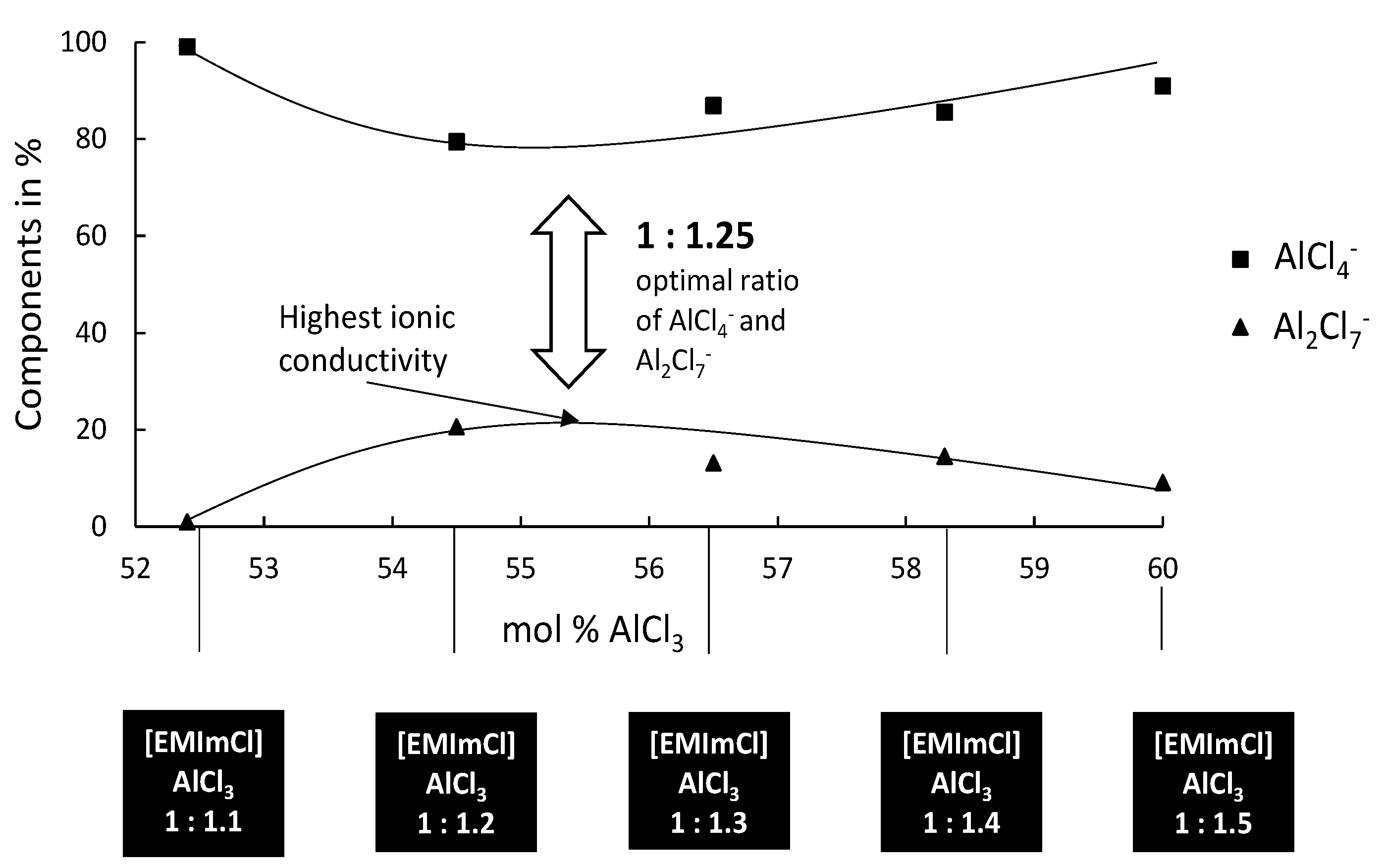
Figure 1 shows the distribution of the active species in the mixing ratio 1:1.1 to 1:1.5. For the Ag–W layers presented in this article, it is important that, in order to deposit films from the previously mentioned electrolyte, no Al may be deposited.
It is known that Al electrodeposits cannot be obtained in basic electrolytes because the organic cations are reduced at less negative potentials than the dominant anions AlCl
4−. In acidic electrolytes, the electroactive species Al
2Cl
7− is responsible for the electrodeposition of Al [
33]. Although the electrochemical reduction of Al from the tetrachloroaluminate complex is possible, there is a parallel decomposition of the organic cation. If we now look at the deposition of an Ag–W layer from our systems ([EMIm]Cl:AlCl
3), the IL should not be too Lewis-acidic as no Al deposition can take place, but has to be Lewis-acidic enough to build sufficiently strong complexes and have a stable chemical equilibrium. Our results show that the Ag–W deposition only succeeds in mixtures of [EMIm]Cl:AlCl
3 in ratios from 1:1 to 1:1.25 even though layer thicknesses and W content are still very low. Results in the literature according to Ferrara et al. [
34] mention an optimum deposition of Al at a ratio of 1: 1.2. Considering the Ag–W depositions from the described mixing ratios, the fact that no Al was found in the prepared layer indicates that Ag and W are preferentially deposited. The reason for this is that the Lewis basicity in the selected mixing ratio of the IL is further shifted into the basic range by the addition of the chloride metal salts, and, thereby, increasing the chloride ion concentration. The deposition under direct-current conditions shows results that resemble the behavior expected in aqueous solutions. As the W content increases, the layer thickness decreases rapidly and vice versa. For layers that would be applicable in the field of contact materials, however, we have not yet been able to achieve the optimum solution with direct-current deposition. Applications in the contact area require layer thicknesses of more than 0.5 µm and a mole fraction of more than
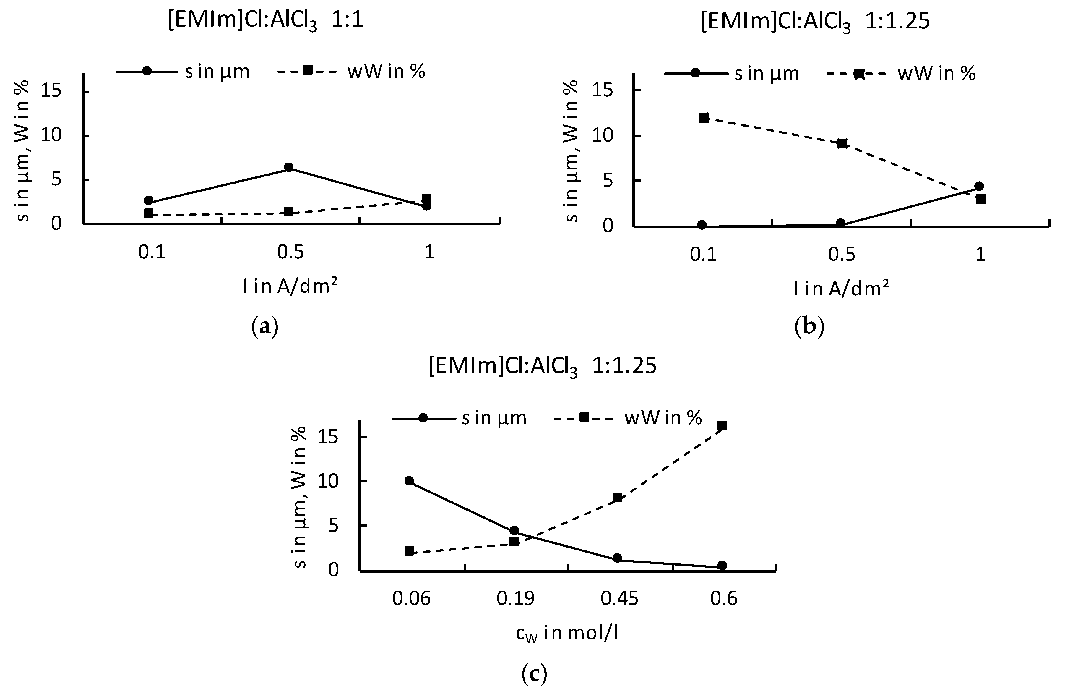
= 50%. However, our experiments showed that, similar to the known behavior on aqueous solutions, higher W content in the electrolyte could also produce a higher W content in the resulting layer. It was found that the mixing ratio [EMIm]Cl:AlCl
3 1:1.25 provides higher layer thicknesses with correspondingly high W contents. However, the direct-current deposits do not provide adequate layer systems. W contents above
= 15% could not be obtained in layers higher than 0.25 μm (
Figure 2).
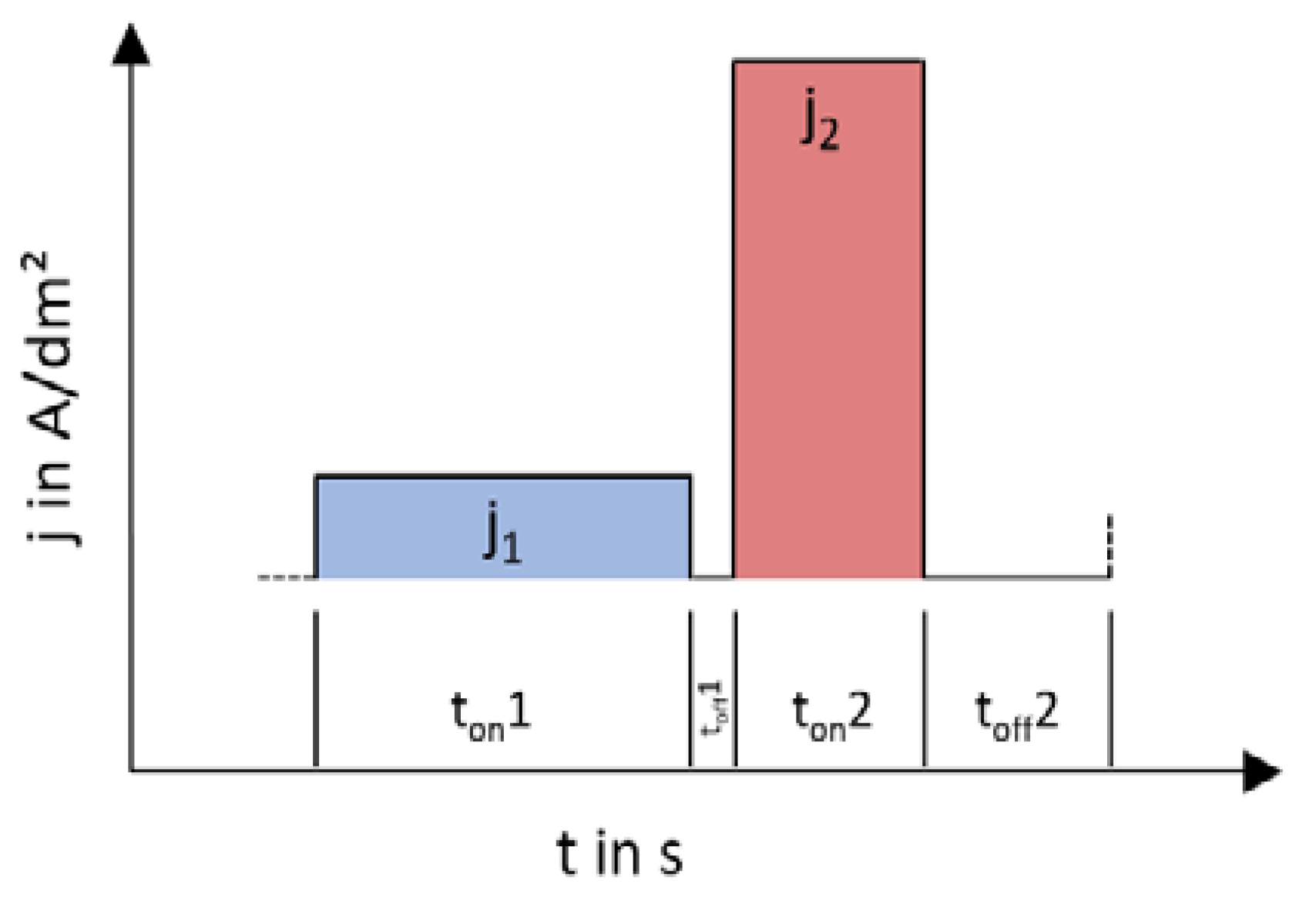
The solution to the problem of low coating thicknesses or low W contents was found to be varying depositions with stepped direct-current. This can achieve higher layer thicknesses and simultaneously higher W contents. Current densities from 0.1 to 10 A/dm
2 and step times from 0.5 to 180 s varied. The layers that can be deposited with the respective current shape are shown in
Figure 3. It is, thus, possible to deposit layers with more than 0.5 μm and more than
= 50%.
Experiments showed that a variation of different current levels, i.e., a double pulse, was successful with a great possible difference. However, a systematic dependence of the different current densities and times could not be determined. Additionally, increasing the layer thickness of the layers, which contain a high amount of W by prolonging the deposition time, has no effect. An explanation for this can be found by considering the resulting double layer at the cathode during the deposition. Unlike aqueous systems, several stages of the electrochemical double layer are formed in ionic liquids. By varying the applied current densities, the diffusion movements at the double layers can be influenced positively and a higher W incorporation rate can be achieved. In order to increase this effect, the pause time between current pulses can be varied further. With this system, it was possible to increase thickness and W content and to produce layers with more than = 50% to 75% W and suitable thickness up to 1 µm. However, the layer thicknesses in the high-W areas are too low to be characterized as galvanic layers. By means of statistical significance analysis, however, it was possible to determine the optimal deposition parameters to get high W percentages and layer thickness over 0.5 µm. The analysis showed that, in DC depositions, only the deposition time is responsible for the resulting layer thickness. Considerations for the single-pulse systems show a layer thickness dependence on ton and toff and an additional dependence of the W content on toff. However, the total deposition time is not relevant to the pulsed deposits in terms of layer thickness or W content. The deposits with the highest W contents and layer thicknesses are conducted with a double pulse. The most important parameters include the effective current density, which should be between 4 and 6 A/dm2, and a deposition time of the first pulse level (ton1) of 10 s.
Optimal conditions seem to prevail by alternating low (
j1 = 1 A/dm
2) and high (
j2 = 10 A/dm
2) current density with
ton1 = 10 s,
ton2 = 5 s, and pause times between pulses of
toff1 = 1 s and
toff2 = 5 s (
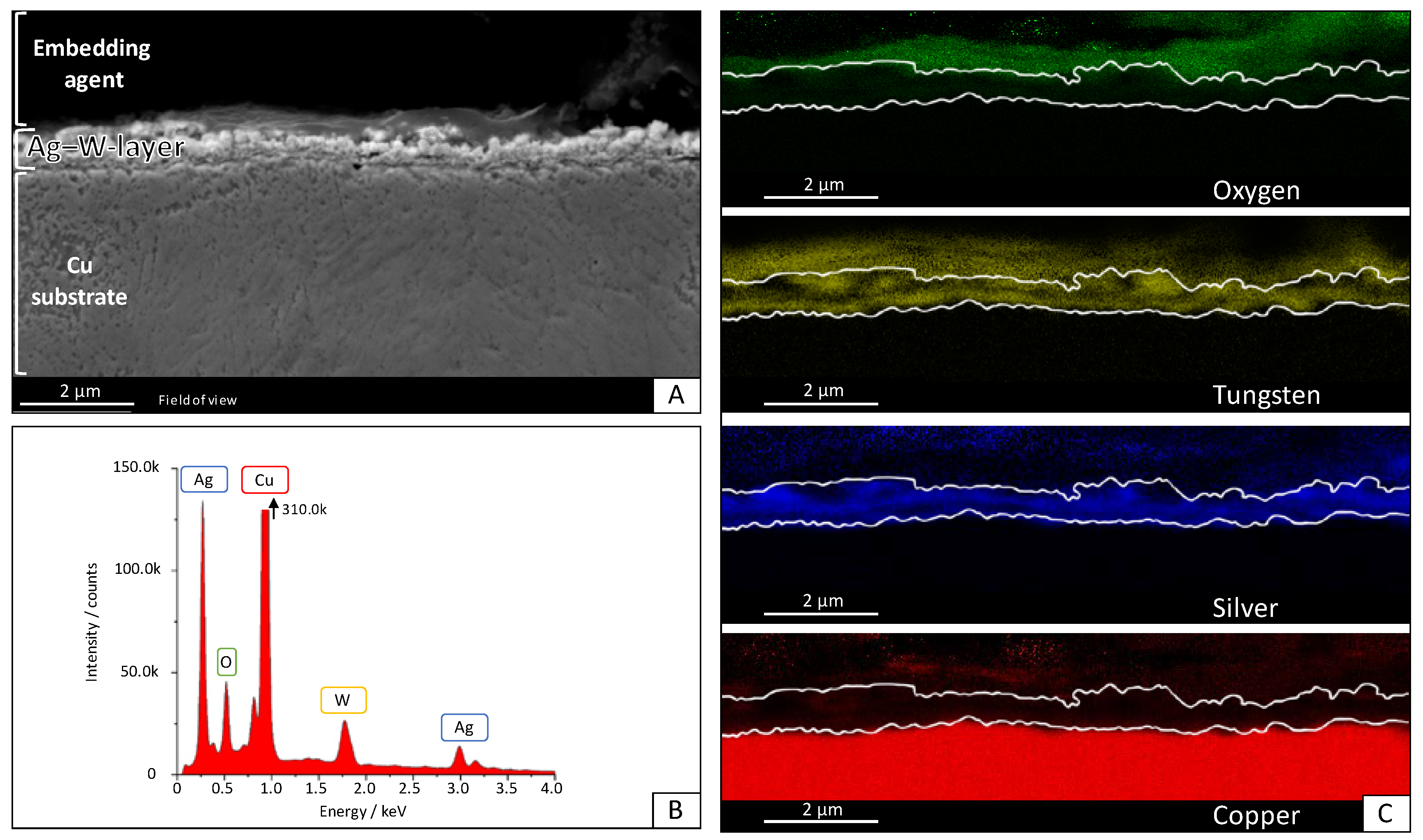
Table 1). An Ag–W layer with
= 50% (measured by ICP-OES) on Cu substrate and 0.5-μm layer thickness is shown in
Figure 4. This layer was deposited by alternating low (
j1 = 1 A/dm
2) and high (
j2 = 10 A/dm
2) current density with
ton1 = 10 s,
ton2 = 5 s, and pause times between pulses of
toff1 = 1 s and
toff2 = 5 s. It has a thickness of 0.5 μm and a W content of
= 50% (
= 36.9%). Another coating, which delivered a layer of
= 5% and was used to measure the resistance, was deposited by alternating low (
j1 = 1.6 A/dm
2) and high (
j2 = 1.1 A/dm
2) current density with
ton1 = 30 s,
ton2 = 24 s, and pause times between pulses of
toff1 = 15 s and
toff2 = 9 s.
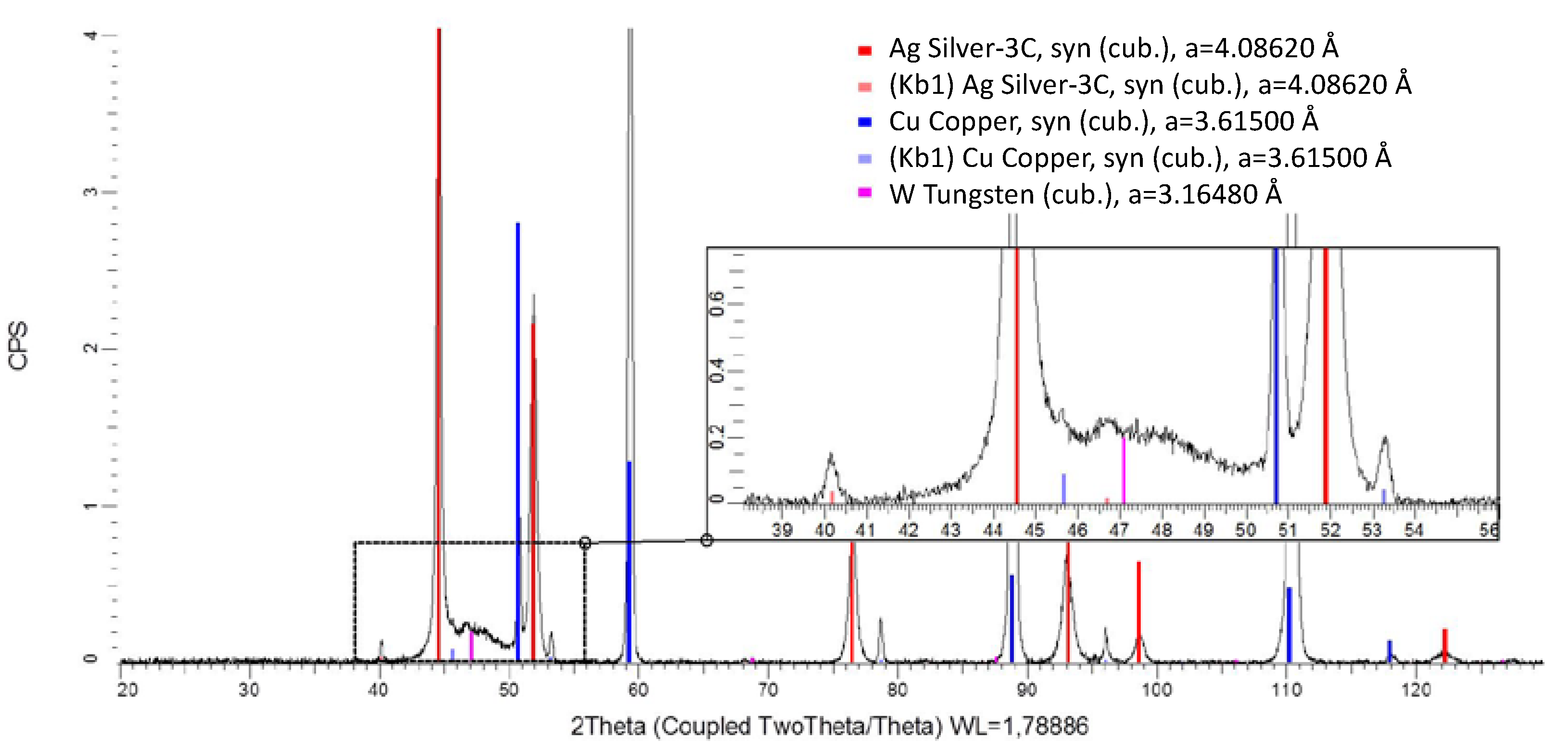
Energy-dispersive X-ray spectroscopy shows that the element distribution is not uniform. It can be seen that, first, an Ag layer grows on the Cu substrate. This confirms the experimental observation that electroless Ag deposition in this electrolyte is a competitive reaction to the initial Ag–W film deposition. However, the possibility of a pure metal layer of Ag and W deposition in this composition by galvanic deposition is novel. Neither Al nor C fragments from the ionic liquid could be found in the layer. C and especially O could only be detected outside the layer in the region of the embedding agent of the cross-section. The oxygen content was measured likewise and must be attributed to fast oxidation during the preparation process. XRD measurements were carried out and a typical diffractogram is shown in
Figure 5. The layer shows at 2θ = 50.7°, 59.2°, 88.8°, 110.1°, and 118° clear peaks for the Cu substrate material. These signals are so prominent because the measured Ag–W layer had a thickness of 0.5 μm, while the information depth of XRD is well above 20 µm. The diffraction peaks at 2θ = 44.5°, 51.8°, 76.2°, 91.3°, 98.6°, and 122.2° can be assigned to crystalline Ag. These signals were expected since the tested layer contains a mass fraction of
= 50% as measured by ICP-OES in the deposition. A peak at 2θ = 47.1° could indicate a nanocrystalline phase. Due to the peak position and width, we suspect W with a grain size below 4 nm. No further peaks were detected in the diffractogram. This suggests that neither Al nor crystalline oxides or fragments of the IL were incorporated into the layer and, therefore, it is a pure Ag–W system, as shown in the scanning electron microscopy (SEM) image. It is also clearly visible in the XRD that there is no solid solution formation. This points to a 2-phase system of the layers obtained.
In order to be able to make a comparison with the existing systems from the sintering processes, hardness measurements were carried out (
Table 2).
The measurements were done with the nano-indenter, as the layers obtained were too thin to measure Vickers hardness in accordance with standards. For comparison to literature data of sintered bulk materiel, the obtained values were converted to Vickers hardness, according to manufacturer specifications. A layer with 50% W and a pure Ag layer were examined. The hardness of the substrate material Cu was also taken into account to rule out that not the layer but the substrate determines the measured values. As a result, it can be seen that the hardness of the Ag–W 50 layer obtained is not in the range of the contact materials produced by powder metallurgy.
Resistivity measurements were carried out for comparison (
Table 3). For this purpose, the layer with
= 50% and one with a very low percentage of W were measured using the four-point probes method.
A comparison with the literature shows that the layers deposited from ionic liquids have a lower resistance than those produced by powder metallurgy. This can be explained by the fact that a more homogeneous distribution of the contained metals was achieved despite the multi-phase system obtained.


