2. Materials and Methods
In the research presented here, the starting solutions were prepared with the application of the following solutions: Tetraethyl orthosilicate (TEOS), purity 99.0%, supplied by Sigma-Aldrich, Poznan, Poland; water; absolute ethanol C2H5OH (EtOH), 99.8%, supplied by Avantor Performance Materials, Gliwice, Poland; and hydrochloric acid, 37%, supplied by Avantor Avantor Performance Materials, Gliwice, Poland and used as a catalyst. The following molar ratios were applied: TEOS:EtOH:H2O:HCl = 1:4:4:0.02. A non-ionic surfactant, Triton X-100, was added to the starting solution in volumetric ratio Triton X-100:TEOS = 0.7. After mixing the components, the sol formation was performed for 3 h in a closed glass vessel at a temperature of 50 °C, using ultrasonic mixing. Then, after cooling down the solutions, they were filtered with the use of syringe filters with a pore size of 0.2 μm. As substrate, polished silicon wafers were used with plane orientation <111> and RMS (Root Mean Square) roughness of σ = 0.7 nm determined from AFM (Atomic Force Microscopy) microscope XE-70 (Park System Corp., Suwon, Korea). The silicon wafers were washed according to the procedure, which included: Mechanical cleaning in water with detergent, rinsing in deionized water, soaking in a 5% ammonia water solution, rinsing in deionized water, rinsing in acetone, and drying. All samples were prepared from the same sol solution. The samples varied in the thickness of SiO2 films, which resulted from the different withdrawal speeds of the substrate from the sol solution. Finally, the fabricated structures were annealed at a temperature of 430 °C over 40 min. In the annealing process, the final properties of the fabricated films were established by the removal of the solvent remains and condensation. Moreover, it is important to note that collapse of the structures occurred as a result of the action of capillary pressure resulting from the high temperature treatment.
The complex refractive index and depolarizing ability of the porous silica films was determined through the ellipsometric method [
13,
14]. The ellipsometry technique uses the light of known polarization, which was incidental on the studied surface. The polarization state of the reflected light was detected. Incidental light was linearly polarized, then the reflected light was usually elliptically polarized. Spectroscopic ellipsometry directly determined two angles, Ψ and Δ. The ellipsometry parameters fulfilled the following Equation (1):
where
i represents imaginary unit, Ψ represents the angle determined from the amplitude ratio between
p- and
s- polarizations, and Δ is the phase shift between the polarized waves. The
rp and
rs are the complex Fresnel reflection coefficients for
p- and
s- polarizations, respectively.
Two types of ellipsometers were used in this study: The multiple angle monochromatic ellipsometer (λ = 632.8 nm) SE400 (Sentech, Berlin, Germany) and the spectroscopic ellipsometer Woollam M-2000 (J.A. Woollam Co., Inc. Lincoln, NE, USA). The thickness
d and refractive index
n of the silica layers were determined through the use of the monochromatic Sentech SE400 ellipsometer. Results obtained by the use of the M2000 ellipsometer enabled determination of the dispersion of the refractive index
n(λ) of the porous silica films. Ellipsometric measurements were conducted in the wavelength range of 190 to 1700 nm. The measurements were performed for three angles of incidence: 60°, 65°, and 70°. The total reflectance measurements on the porous SiO
2 layers were performed by the use of an ILN-472 integrating sphere [
15] covered with a Spectralon [poly(tetra-fluoroethylene)] and UV/VIS/NIR spectrophotometer (V-570 JASCO Co., Tokyo, Japan). The diameter of the sphere was 150 mm. This instrument uses the xenon lamp as a light source, which enables measurement of the reflectance spectra in the 190–2500-nm wavelength range. The sample was illuminated with a light beam of 10-mm diameter and the reflected light signal was collected under an angle of 8° from the normal output port.
The surface roughness of the porous SiO
2 films was determined by using the XE-70 atomic force microscope (Park System Corp., Suwon, Korea). The AFM imaging was performed in the noncontact AFM mode (NC-AFM). The Tip300Al cantilever from Budget Sensors was used. The SEM images were made using the Versa 3D Field Emission Gun (FEI Technologies Inc, Hillsboro, OR, USA) scanning electron microscope. Bidirectional reflection distribution function (BRDF) measurements were conducted with an automatic scatterometer (homemade). It consisted of a 635 nm laser diode as the light source. The charge couple device (CCD, Hamamatsu Photonics, Hamamatsu, Japan) ruler with 512 diode elements was used for the detection of scattered light. The resolution angle per pixel was 0.06, which was considered to be a suitable value for that type of measurement. The scattering angles ranged from 40° to 50°. The measurements were performed in the plane of light incidence. All BRDF measurements were taken in the plane of incidence with the
s-polarized incident beam. In the measurements, the BRDF (θ
s) was determined. The relationship between the measured scattered intensity
Ps (θ
s) and the BRDF function is given by Equation (2):
where
Pi is the intensity of incident radiation, and Ω is the detector angular acceptance. The angular and spectral dependence of scattered radiation from any surfaces (both random and periodical) can be described by scalar theory [
16], from which the roughness and autocorrelation length of the BRDF function can be determined.
3. Results
We present results of optical studies of three porous SiO
2 films with different thicknesses deposited on the Si substrate chosen from the sets of porous SiO
2 layers (named P1, P2, and P3, respectively). During all the measurements, the relative humidity in the room was around 52%.
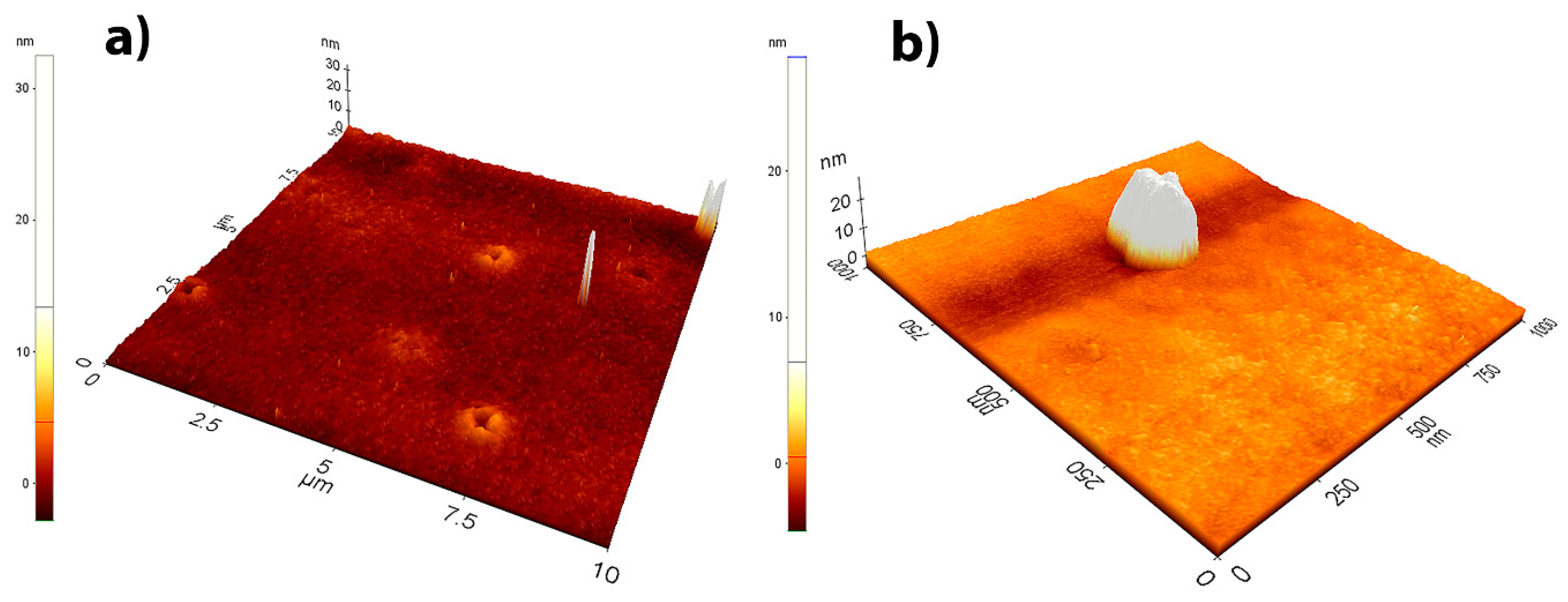
Figure 1 shows the AFM profile of sample P1. The detailed investigation of the films’ surface showed the presence of open pores with a size less than 1 µm (
Figure 1a). Moreover, point defects with a size not exceeding 100 nm occurred occasionally on the surface of the film (
Figure 1b).
Images of the Atomic Force Microscopy (AFM) remaining P2 and P3 samples were very similar so they are not shown in the article. All of the tested samples presented a very flat nature. The roughness values calculated from AFM images are displayed in column 4 of
Table 1. These values are very small and typical of good quality sol-gel-derived films.
Figure 2 and
Figure 3 show SEM images of the surface and cross-sections of the SiO
2 layers on a silicon substrate for samples P1, P2, and P3.
In
Figure 2a, the characteristic defects are clearly visible in the form of cavities with a size of around 1 µm, distributed relatively evenly over the entire surface of porous silicon dioxide film. However, in the cross-section of the film, which is shown in
Figure 2b, one can distinguish brighter areas at intervals of around 1 µm directly adjacent to the ground. Our interpretation is as follows: These areas were defects in the form of open and closed pores, resulting from the thermal decomposition of organic matter during the sol-gel production process. Closed pores were filled with gaseous decomposition products used in the synthesis of substrates.
The measured thickness of the layer was around 500, 600, and 800 nm (
Figure 3a–c). Their values were similar to those determined using an ellipsometer. The surface of the outer pores was negligible in relation to the total surface of the material. The proportion of these defects in the total light scattering was, therefore, small. However, the pores occurring in the layer’s volume were distributed around 100 times more densely and they had a predominant impact on the optical properties of silica films. The decrease in the refractive index was mainly due to the presence of closed pores. The spectral dependences of ellipsometric angles Ψ and
Δ for samples P1, P2, and P3 are shown in
Figure 4a–c, respectively. To analyze the data, we combined all angular spectra and performed the fitting to all data simultaneously. In
Figure 4, ellipsometric parameters fitted from an extended Cauchy model [
17,
18] are presented. The film model assumed the presence of roughness, the values of which were determined from AFM.
The dashed lines in
Figure 4 represent the fitted results. As can be observed, the theoretical model of the porous silica film provided a very good fit. The spectral dispersion of the refractive index
n and extinction coefficient
k are shown in
Figure 5.
Spectral dependence of optical constants showed a normal dispersion, which is typical of dielectric layers [
19]. Thickness
d and the refractive index
n for λ = 632.8 nm determined from ellipsometric measurements are presented in columns 3 and 6 of
Table 1. Solid silica is an almost ideal dielectric and did not show absorption across a very wide spectral range of wavelength from 150 to 3000 nm [
20,
21]. However, in the porous silica films, low optical losses were observed in UV-VIS light. This phenomenon occurred due to elastic scattering and absorption by the porous silica films. The absorption in the UV spectral range can be described by Urbach’s tails’ band [
22,
23]. The part of radiation was scattered elastically (Rayleigh scattering) [
24]. In the real experiment, we determined the so-called pseudo-extinction coefficient, which is the sum of elastic scattering (
ke) and physical absorption coefficient (
ka),
kfull = ke + ka. The
kfull extinction coefficient is shown in
Figure 5b (for dense silica
ke = 0). The values of
d and
n determined from monochromatic laser He-Ne ellipsometer (SENTECH 400) measurements are presented in columns 2 and 5 of
Table 1. The values of refractive indices
n obtained by the use of both ellipsometers were similar. Small differences in thickness can result from performing measurements on various areas of samples (different measurement conditions, especially varying levels of humidity).
The refractive index
n of the porous silica films was strongly related to porosity
p of the films according to following formula, Equation (3):
where
n is the effective refractive index of the film;
nb is refractive index of the dense silica,
nb = 1.457 at 632.8 nm; and
p denotes porosity of the films. The simplified formula (Equation (3)) is used when the light wavelength is much larger than the typical nanocrystal size and the dielectric response of porous silica can be modelled using the effective medium approximation (EMA). In the Bruggeman model, the refractive index of porous silica (
np-sio2) can be presented by Equation (4):
The obtained values of porosity (in %) for porous silica films are shown in column 7 of
Table 1. The total reflectance on porous silica films P1, P2, and P3 are presented in
Figure 6.
In
Figure 6, the spectral dependence of reflection coefficient
RSi(λ) of flat silicon wafer covered by native oxide with a thickness of 2 nm is presented. As can be observed, the spectral reflection from the silicon surface was an envelope for the interference maxima of the reflections from the presented samples in the area of 500–1700 nm. This means that the maxima were equal to the reflection coefficient from the Si substrate, which was in full compliance with the Fresnel theory. For light wavelengths less than 300 nm, the deviation between the classic Fresnel model and experimental results was noticed. It was due to strong Rayleigh scattering. As one could see, for films with higher thickness the light flux attenuation was higher. In ellipsometric analysis, only the coherent part of reflected radiation is considered. The total intensity of scattered radiation from a real surface is the sum of the coherent
Rc (mainly specular reflectance) and the incoherent
Ri scattering (mainly diffusive) [
25]. These two components,
Rc and
Ri, cannot be separated in a single measurement. However, in our experimental studies, it was assumed that the incoherent component was negligible, thus the specular reflected radiation was nearly coherent. The spectrophotometric technique only measures the magnitude of reflectance
R(λ). The optical parameters of a film may be determined by the means of the envelope method [
26]. This consists of plotting two curves enveloping the extrema of the spectrum
R(λ) and analyzing these envelopes. In this work, only the maximum envelope was analyzed. Because the Si substrate has a larger refractive index than silica film, the values of reflection maxima are expressed as Equation (5):
where
NSi(λ) =
nSi(λ) −
kSi(λ)
i is a complex refractive index for silicon substrate. With regard to transparent films, the upper reflectance envelope should only overlap with the reflectance of the substrate. The excellent agreement with the Fresnel theory was observed for wavelengths longer than 600 nm. As can be observed in
Figure 5b, for wavelengths longer than 600 nm, the absorption in p-SiO
2 films practically disappeared. Reflectance for shorter wavelengths gave divergent results with predictions of the Fresnel model, even if we took into account weak absorption in films.
Figure 7 presents the reflection coefficients of porous SiO
2 film (sample P2) and the reflection coefficients for the normal light incidence calculated from the model using the optical and geometrical quantities determined from ellipsometric study.
Maxima of reflectance magnitudes determined from spectrophotometric measurements were lower than calculated from the model with which the weak absorption in film was assumed. The additional absorption was associated with light scattering. Due to elastic scattering on the porous film structure, a proportion of the photons was removed from the specular beam and the reflected light intensity was attenuated. Dense SiO
2 silica was transparent across a broad spectrum of light. Even for wavelengths less than 190 nm, absorption was negligible. However, if the silica had a porous structure, optical losses may have occurred in the ultraviolet, short visible light, range. The presence of pores was the cause of absorption and the elastic scattering in the bulk of films. The losses of the light stream passing through the film were caused by elastic scattering (Rayleigh scattering). Therefore, in optical measurements, the determined extinction coefficient was equal to the elastic scattering coefficient (
ke). Thus,
Figure 5b rather shows a pseudo-extinction coefficient. We estimated the scattering component caused by the surface roughness
σ of porous silica films using following formula, Equation (6):
where
R0 is reflection coefficient of the specularly reflected light.
The expression (Equation (6)) is derived from scalar scattering theory [
27,
28]. Roughness σ was determined from the AFM measurements, yielding roughness values of the studied films lower than 2 nm. Thus, the contribution of the surface scattering to the total reflectance, calculated according to Equation (6), equaled 0.3% for the 300 nm wavelength and 0.01% for 600 nm, respectively. Thus, the surface scattering was neglected in further consideration. Moreover, the specular reflection for bulk scattering layers must differ from an ideal thin film reflectance described by Fresnel theory. The formula for specular reflectance must be modified by scattering factor, μ, for specified diffusive film. Taking into account scattering in bulk, the following formula was derived (Equation (7)):
where
r1 and
r2 are Fresnel coefficients for air-film and film-substrate interfaces, respectively, and β is a phase term associated with the film:
, where
N1 =
n1 −
ik1 is the complex refractive index and
d is the thickness of the film.
Scattering factor
μ is dependent upon film thickness
d and scattering coefficient α
scat which is generally a function of wavelength λ and can be expressed as: μ(λ) = exp[−
αscat(λ)
d]. Taking into account modified reflection, Equation (7), we determined scattering coefficient α
scat(λ). Wavelength dependences of α
scat for the studied films are shown in
Figure 8.
As may be observed, α
scat drops with increases of wavelengths longer than 500 nm. This behavior cannot be related to light absorption in the film. Rather, it concerns elastic light scattering in a non-coherent way. To confirm this hypothesis, we performed combined reflectometric and ellipsometric measurements [
29,
30]. This enabled determination of the attenuation arising from the removal of photons from the light beam. The evidence of light incoherence in reflected radiation can be obtained through studies of the polarization state of reflected radiation. Depolarization is frequently the effect of the appearance of an incoherent light component in specular reflectance [
31]. The phenomenon of incoherent elastic dispersion relates to porous silica layers. In
Figure 9a–c, the spectral reflectance
R(λ) and depolarization
D(λ) coefficients (ratio of the reflected light in depolarized manner to the total reflected beam) in the range of 200 to 300 nm are shown.
The visible extrema observed in the spectral depolarization coefficient were related to interference phenomena appearing in porous films. Wavelength positions of reflectance minima overlapped with maxima of depolarization. This can be explained as follows: When reflection from the film was minimal within porous film, the quasi standing wave arose, which caused amplitude to reach maximum. Light scattering also caused the depolarization to achieve its largest values; additionally, the contribution of incoherent light in reflected specular reflection was at its largest. For wavelengths longer than 500 nm, elastic scattering in the bulk of films disappeared. Furthermore, the scattering from air–film and film–substrate interfaces were practically negligible. Reflectance maxima coincided with the envelope of the spectral curve of reflection from silicon substrate in long wavelength spectra. For wavelengths shorter than 500 nm, the interference maxima were smaller than their Fresnel equivalents because of incomplete coherence in films. This was due to the fact that part of the radiation passing through the layer was diffused in a diffusive manner. The consequence of this was the partial depolarization of the reflected beam. For example, for sample P3 (
Figure 9c), the depolarization coefficient was the highest, which corresponded to lower reflection values in the UV range (
Figure 5). For the purpose of qualitative estimation of the angular scatter of light reflected from porous samples, angular resolved scattering measurements were performed.
In
Figure 10, the angular dependence of the Bidirectional Reflectance Distribution Function (BRDF) function determined for the presented
p-SiO
2 samples and for silicon substrate are shown.
Bidirectional Reflectance Distribution Function (BRDF) values were normalized through dividing them by reflection coefficient values for 650 nm. As a result of this, the relative dispersion observed outside the reflection angles did not depend on the refractive index, which is a function of the pore volume in the film (porosity). Because the pore sizes were small in relation to the wavelength, the scattering was of Rayleigh type, which is expressed by constant coefficient values of scattering outside the specular reflection area. As could be observed, the plateau heights in the BRDF plots increased as the porosity of the layers increased. A much stronger effect of volume scattering can be observed for materials with large porosity, for example, aerogels [
32].


