Fabrication, Wear, and Corrosion Resistance of HVOF Sprayed WC-12Co on ZE41 Magnesium Alloy


Abstract
:1. Introduction
2. Materials and Methods
2.1. Materials
2.2. Spraying Process
2.3. Specimen Examination
2.4. Tribological Test
2.5. Corrosion Test
3. Results and Discussion
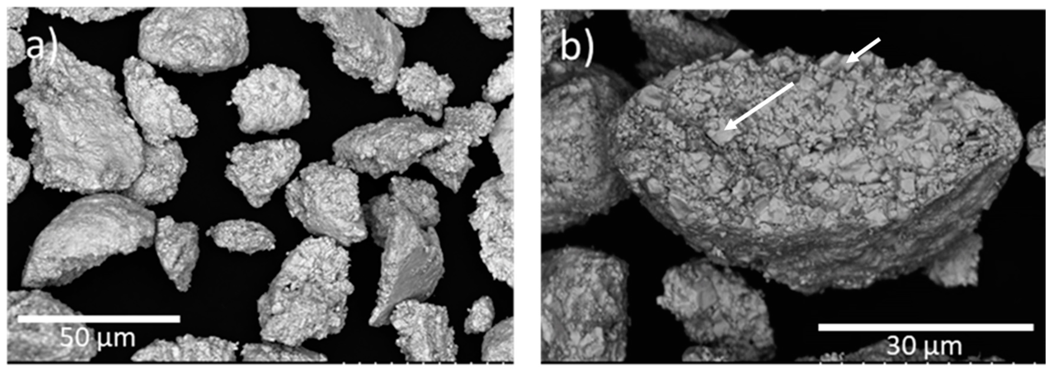
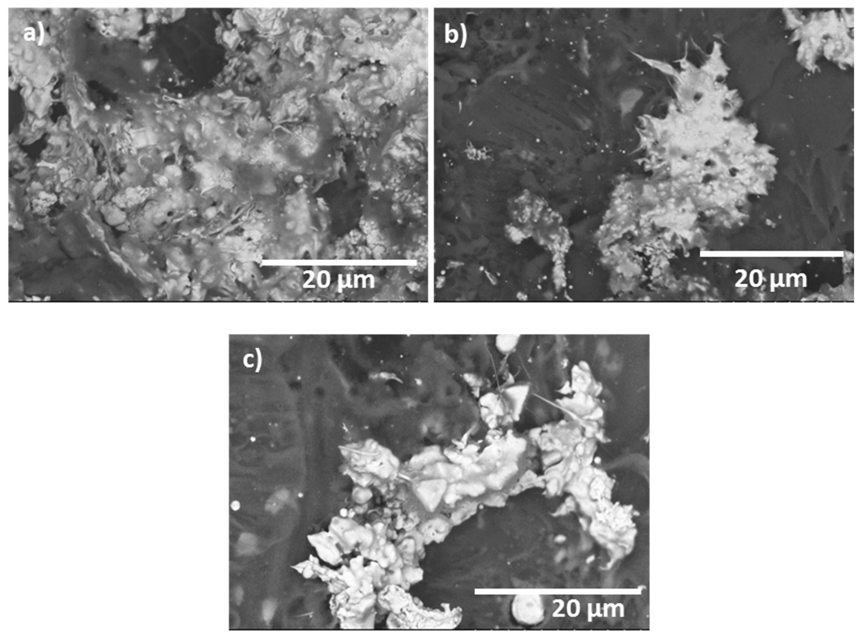
3.1. Powder and Spraying Characterization
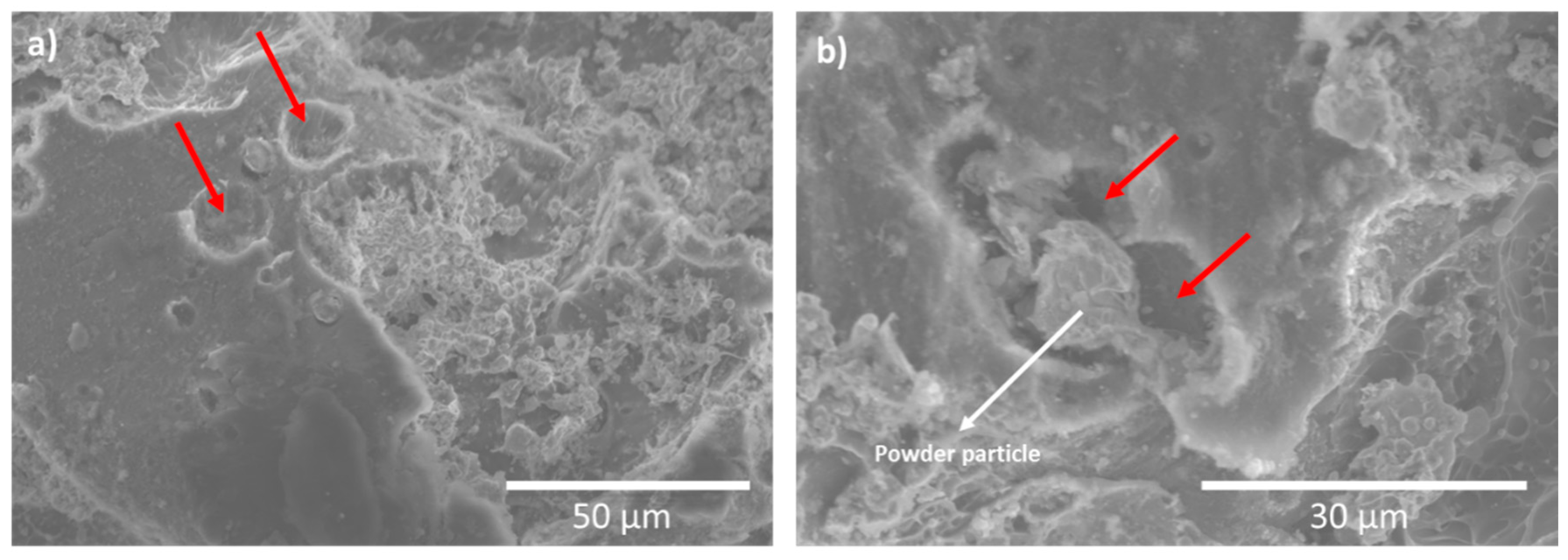
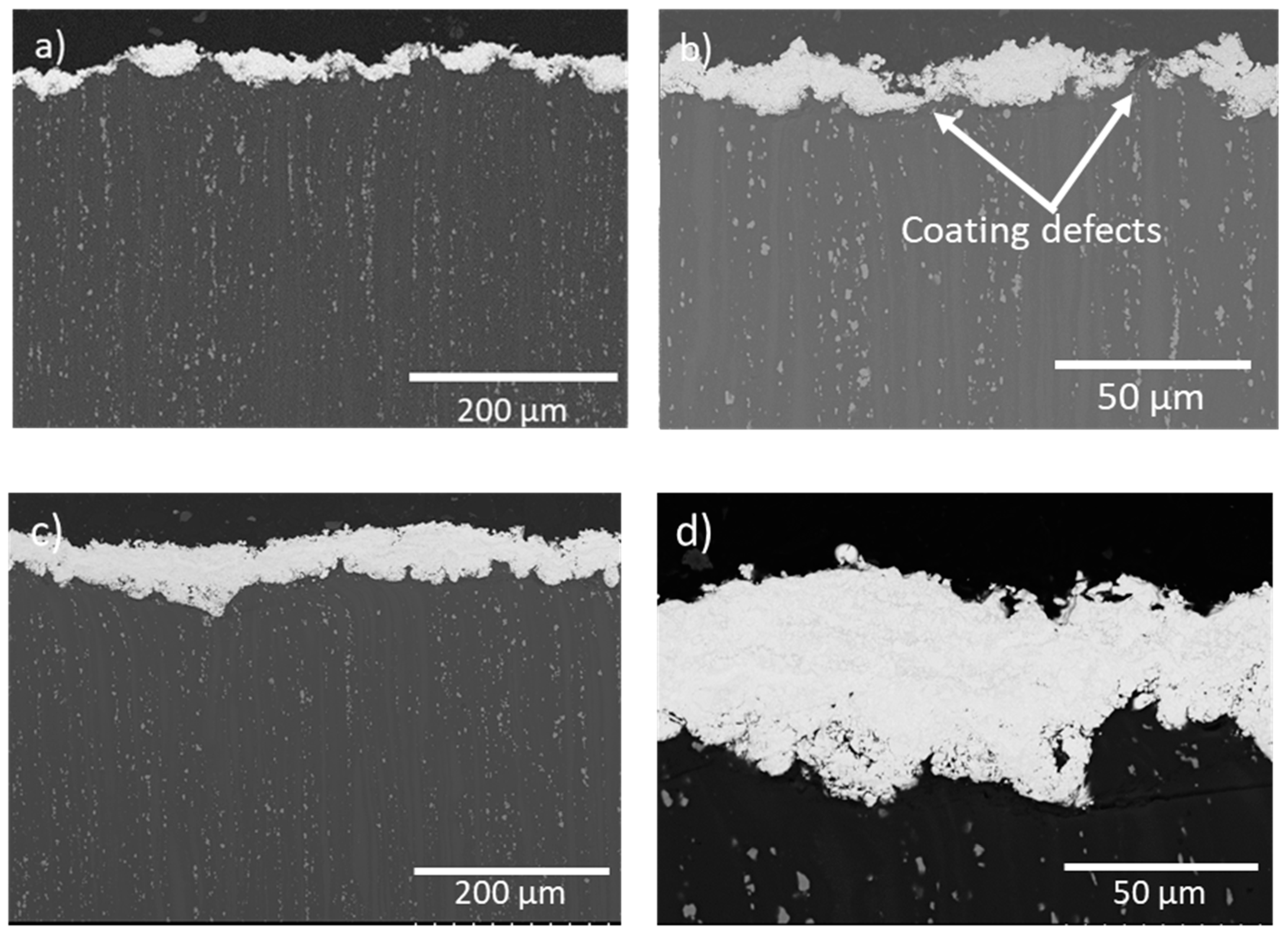
3.2. Coatings Characterization
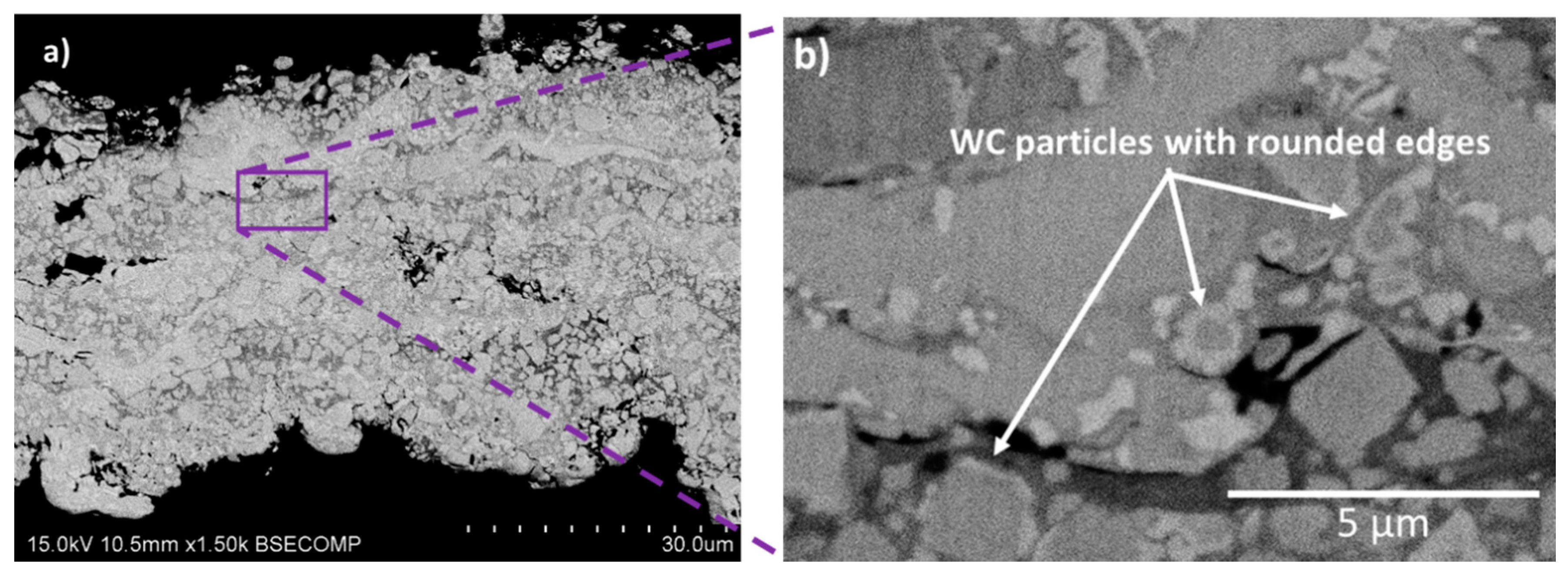
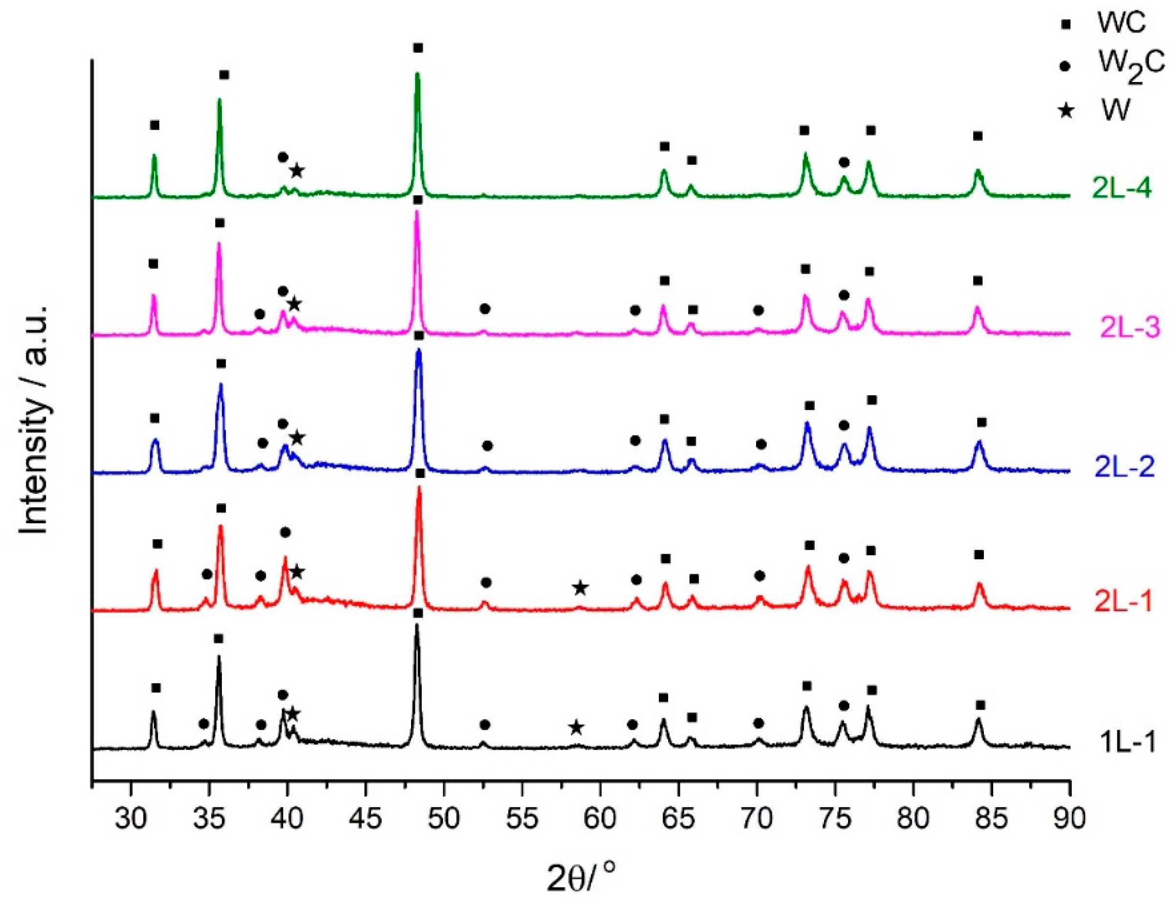
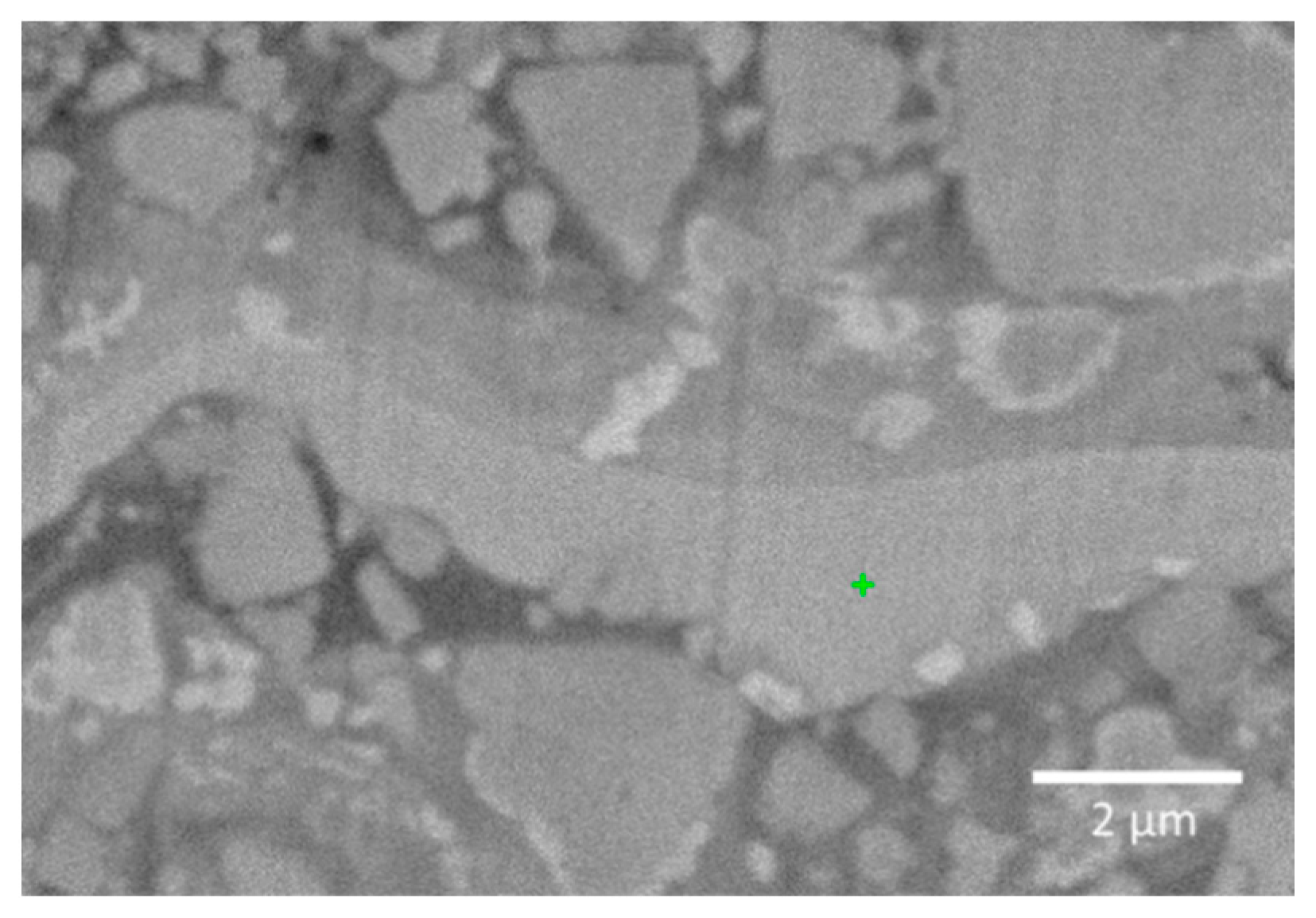
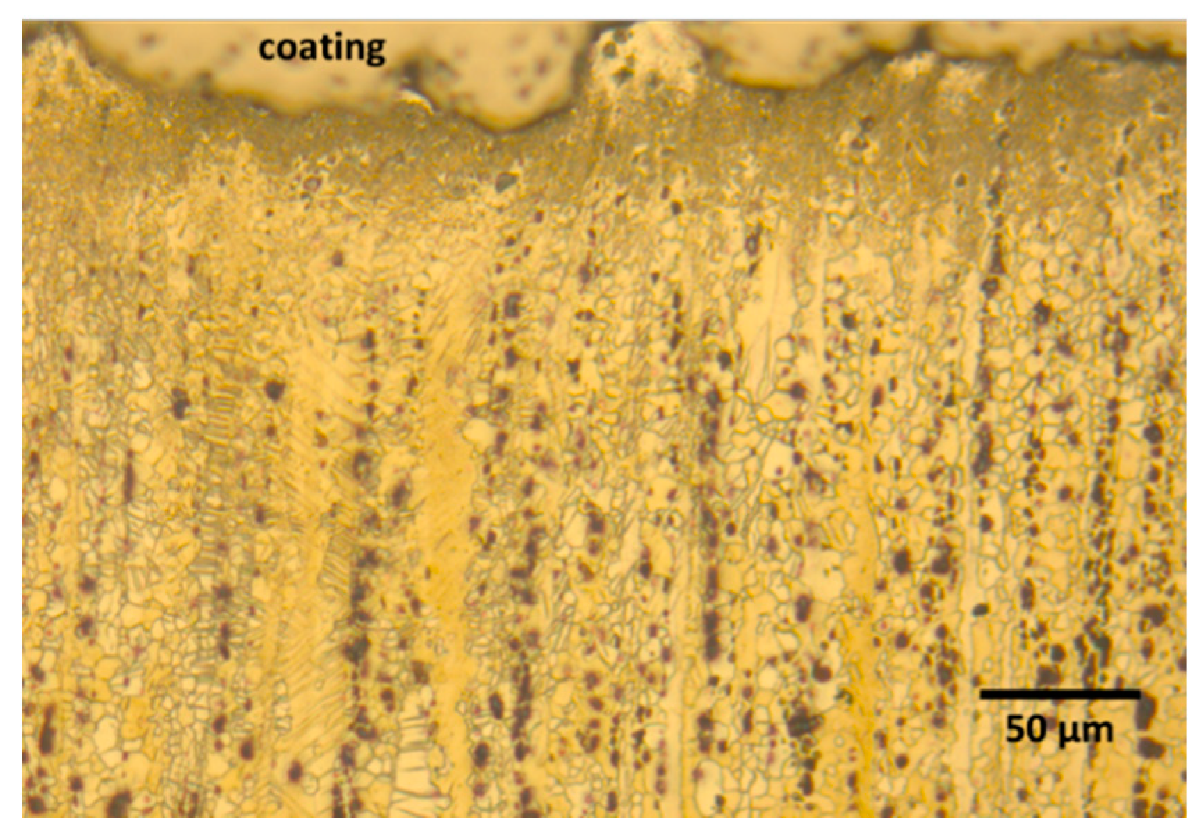
3.3. Coatings Microstructure
2 W2C + O2 ⇆ 2 W2(CO)
W2(CO) ⇆ 2 W + CO
2 WC ⇆ W2C + C
3 Co + 3 WC + O2 ⇆ Co3W3C + 2 CO
12 Co + 12 WC + 5 O2 ⇆ 2 Co6W6C + 10 CO
3.4. Tribological Results
3.5. Electrochemical Test
4. Conclusions
Author Contributions
Funding
Acknowledgments
Conflicts of Interest
References
- Mehta, D.S.; Masood, S.H.; Song, W.Q. Investigation of wear properties of magnesium and aluminum alloys for automotive applications. J. Mater. Process. Technol. 2004, 155, 1526–1531. [Google Scholar] [CrossRef]
- Mordike, B.L.; Ebert, T. Magnesium Properties-applications-potential. Mater. Sci. Eng. A 2001, 302, 37–45. [Google Scholar] [CrossRef]
- Makar, G.L.; Kruger, J. Corrosion of magnesium. Int. Mater. Rev. 1993, 38, 138–153. [Google Scholar] [CrossRef]
- Ardelean, H.; Frateur, I.; Zanna, S.; Atrens, A.; Marcus, P. Corrosion protection of AZ91 magnesium alloy by anodizing in niobium and zirconium-containing electrolytes. Corros. Sci. 2009, 51, 3030–3038. [Google Scholar] [CrossRef]
- Chai, L.; Yu, X.; Yang, Z.; Wang, Y.; Okido, M. Anodizing of magnesium alloy AZ31 in alkaline solutions with silicate under continuous sparking. Corros. Sci. 2008, 50, 3274–3279. [Google Scholar] [CrossRef]
- Pan, F.; Yang, X.; Zhang, D. Chemical nature of phytic acid conversion coating on AZ61 magnesium alloy. Appl. Surf. Sci. 2009, 255, 8363–8371. [Google Scholar] [CrossRef]
- Torres, B.; Taltavull, C.; López, A.J.; Campo, M.; Rams, J. Al/SiCp and Al11Si/SiCp coatings on AZ91 magnesium alloy by HVOF. Surf. Coat. Technol. 2015, 261, 130–140. [Google Scholar] [CrossRef]
- López, A.J.; Rams, J.; Ureña, A. Sol–gel coatings of low sintering temperature for corrosion protection of ZE41 magnesium alloy. Surf. Coat. Technol. 2011, 205, 4183–4191. [Google Scholar] [CrossRef]
- Taltavull, C.; Torres, B.; Lopez, A.J.; Rodrigo, P.; Otero, E.; Atrens, A.; Rams, J. Corrosion behaviour of laser surface melted magnesium alloy AZ91D. Mater. Des. 2014, 57, 40–50. [Google Scholar] [CrossRef]
- Hu, R.-G.; Zhang, S.; Bu, J.-F.; Lin, C.-J.; Song, G.-L. Recent progress in corrosion protection of magnesium alloys by organic coatings. Prog. Org. Coat. 2011, 73, 129–141. [Google Scholar] [CrossRef]
- Zhong, C.; Liu, F.; Wu, Y.; Le, J.; Liu, L.; He, M.; Zhu, J.; Hu, W. Protective diffusion coatings on magnesium alloys: A review of recent developments. J. Alloys Compd. 2012, 520, 11–21. [Google Scholar] [CrossRef]
- Gray, J.E.; Luan, B. Protective coatings on magnesium and its alloys—A critical review. J. Alloys Compd. 2002, 336, 88–113. [Google Scholar] [CrossRef]
- Romanov, D.A.; Goncharova, E.N.; Budovskikh, E.A.; Gromov, V.E.; Ivanov, Y.F.; Teresov, A.D.; Kazimirov, S.A. Structure of electroexplosive TiC–Ni composite coatings on steel after electron-beam treatment. Russ. Metall. 2016, 2016, 1064–1071. [Google Scholar] [CrossRef]
- Budovskikh, E.A.; Gromov, V.E.; Romanov, D.A. The formation mechanism providing high-adhesion properties of an electric-explosive coating on a metal basis. Dokl. Phys. 2013, 58, 82–84. [Google Scholar] [CrossRef]
- Arrabal, R.; Pardo, A.; Merino, M.C.; Mohedano, M.; Casajús, P.; Merino, S. Al/SiC thermal spray coatings for corrosion protection of Mg–Al alloys in humid and saline environments. Surf. Coat. Technol. 2010, 204, 2767–2774. [Google Scholar] [CrossRef]
- Kubatík, T.F.; Pala, Z.; Neufuss, K.; Vilémová, M.; Mušálek, R.; Stoulil, J.; Slepička, P.; Chráska, T. Metallurgical bond between magnesium AZ91 alloy and aluminium plasma sprayed coatings. Surf. Coat. Technol. 2015, 282, 163–170. [Google Scholar] [CrossRef]
- Sidhu, T.S.; Agrawal, R.D.; Prakash, S. Hot corrosion of some superalloys and role of high-velocity oxy-fuel spray coatings-A review. Surf. Coat. Technol. 2005, 198, 441–446. [Google Scholar] [CrossRef]
- Mandal, D.; Viswanathan, S. Effect of heat treatment on microstructure and interface of SiC particle reinforced 2124 Al matrix composite. Mater. Charact. 2013, 85, 73–81. [Google Scholar] [CrossRef]
- Tao, Y.; Xiong, T.; Sun, C.; Kong, L.; Cui, X.; Li, T.; Song, G.-L. Microstructure and corrosion performance of a cold sprayed aluminium coating on AZ91D magnesium alloy. Corros. Sci. 2010, 52, 3191–3197. [Google Scholar] [CrossRef]
- Spencer, K.; Fabijanic, D.M.; Zhang, M.-X. The use of Al–Al2O3 cold spray coatings to improve the surface properties of magnesium alloys. Surf. Coat. Technol. 2009, 204, 336–344. [Google Scholar] [CrossRef]
- Campo, M.; Carboneras, M.; López, M.D.; Torres, B.; Rodrigo, P.; Otero, E.; Rams, J. Corrosion resistance of thermally sprayed Al and Al/SiC coatings on Mg. Surf. Coat. Technol. 2009, 203, 3224–3230. [Google Scholar] [CrossRef]
- Taltavull, C.; Lopez, A.J.; Torres, B.; Atrens, A.; Rams, J. Optimisation of the high velocity oxygen fuel (HVOF) parameters to produce effective corrosion control coatings on AZ91 magnesium alloy. Mater. Corros. 2015, 66, 423–433. [Google Scholar] [CrossRef]
- Tobergte, D.R.; Curtis, S. Handbook of Thermal Spray Technology; ASM International: Cleveland, OH, USA, 2013; Volume 53, ISBN 9788578110796. [Google Scholar]
- García-Rodríguez, S.; Torres, B.; López, A.J.; Otero, E.; Rams, J. Characterization and mechanical properties of stainless steel coatings deposited by HVOF on ZE41 magnesium alloy. Surf. Coat. Technol. 2019, 359, 73–84. [Google Scholar] [CrossRef]
- García-Rodríguez, S.; López, A.J.; Torres, B.; Rams, J. 316L stainless steel coatings on ZE41 magnesium alloy using HVOF thermal spray for corrosion protection. Surf. Coat. Technol. 2016, 287, 9–19. [Google Scholar] [CrossRef]
- García-Rodríguez, S.; Torres, B.; Lopez, A.J.; Rainforth, W.M.; Otero, E.; Muñoz, M.; Rams, J. Wear Resistance of Stainless Steel Coatings on ZE41 Magnesium Alloy. J. Therm. Spray Technol. 2018, 27, 1615–1631. [Google Scholar] [CrossRef]
- Stewart, D.A.; Shipway, P.H.; McCartney, D.G. Microstructural evolution in thermally sprayed WC-Co coatings: Comparison between nanocomposite and conventional starting powders. Acta Mater. 2000, 48, 1593–1604. [Google Scholar] [CrossRef]
- Di Girolamo, E.S. Thermally sprayed nanostructured coatings for anti-wear and TBC applications: State-of-the-art and future perspectives. In Anti- Abrasive Nanocoatings; Woodhead Publishing: Cambridge, UK, 2015; pp. 513–541. [Google Scholar]
- Han, J.C.; Jafari, M.; Park, C.G.; Seol, J.B. Microstructure-property relations in WC-Co coatings sprayed from combinatorial Ni-plated and nanostructured powders. Mater. Charact. 2017. [Google Scholar] [CrossRef]
- Hsiao, W.T.; Su, C.Y.; Huang, T.S.; Liao, W.H. Wear resistance and microstructural properties of Ni-Al/h-BN/WC-Co coatings deposited using plasma spraying. Mater. Charact. 2013. [Google Scholar] [CrossRef]
- Liu, Y.; Hang, Z.; Xi, N.; Chen, H.; Ma, C.; Wu, X. Erosion-Corrosion Behavior of HVOF WC-Co Coating in Cl−and SO 42− Containing Solutions. Appl. Surf. Sci. 2018, 431, 55–59. [Google Scholar] [CrossRef]
- Matthews, S.J.; James, B.J.; Hyland, M.M. Microstructural influence on erosion behaviour of thermal spray coatings. Mater. Charact. 2007, 58, 59–64. [Google Scholar] [CrossRef]
- Souza, V.A.D.; Neville, A. Corrosion and synergy in a WC-Co-Cr HVOF thermal spray coating-Understanding their role in erosion-corrosion degradation. Wear 2005, 259, 171–180. [Google Scholar] [CrossRef]
- Wang, Q.; Chen, Z.H.; Ding, Z.X. Performance of abrasive wear of WC-12Co coatings sprayed by HVOF. Tribol. Int. 2009, 1046–1051. [Google Scholar] [CrossRef]
- Ma, N.; Guo, L.; Cheng, Z.; Wu, H.; Ye, F.; Zhang, K. Improvement on mechanical properties and wear resistance of HVOF sprayed WC-12Co coatings by optimizing feedstock structure. Appl. Surf. Sci. 2014, 364–371. [Google Scholar] [CrossRef]
- López, A.J.; Rams, J. Protection of carbon steel against molten aluminum attack and high temperature corrosion using high velocity oxygen-fuel WC-Co coatings. Surf. Coat. Technol. 2015, 262, 123–133. [Google Scholar] [CrossRef]
- Standard Test Method for Pull-Off Strength of Coatings Using Portable Adhesion Testers; ASTM International: West Conshohocken, PA, USA, 2017; ASTM D4541.
- ISO Metallic Materials—Vickers Hardness Test—Part 1: Test Method; International Organization for Standardization (ISO): Geneva, Switzerland, 2018; ISO 6507-1:2018.
- Parco, M.; Zhao, L.; Zwick, J.; Bobzin, K.; Lugscheider, E. Investigation of HVOF spraying on magnesium alloys. Surf. Coat. Technol. 2006, 201, 3269–3274. [Google Scholar] [CrossRef]
- Picas, J.A.; Rupérez, E.; Punset, M.; Forn, A. Influence of HVOF spraying parameters on the corrosion resistance of WC-CoCr coatings in strong acidic environment. Surf. Coat. Technol. 2013, 225, 47–57. [Google Scholar] [CrossRef]
- Sudaprasert, T.; Shipway, P.H.; Mccartney, D.G. Sliding wear behaviour of HVOF sprayed WC-Co coatings deposited with both gas-fuelled and liquid-fuelled systems. Wear 2003, 255, 943–949. [Google Scholar] [CrossRef]
- Bartuli, C.; Valente, T.; Cipri, F.; Bemporad, E.; Tului, M. Parametric study of an HVOF process for the deposition of nanostructured WC-Co coatings. J. Therm. Spray Technol. 2005, 14, 187–195. [Google Scholar] [CrossRef]
- Zhan, Q.; Yu, L.; Ye, F.; Xue, Q.; Li, H. Quantitative evaluation of the decarburization and microstructure evolution of WC-Co during plasma spraying. Surf. Coat. Technol. 2012, 206, 4068–4074. [Google Scholar] [CrossRef]
- Lou, D.; Hellman, J.; Luhulima, D.; Liimatainen, J.; Lindroos, V.K. Interactions between tungsten carbide (WC) particulates and metal matrix in WC-reinforced composites. Mater. Sci. Eng. A 2003, 340, 155–162. [Google Scholar] [CrossRef]
- Zhang, S.H.; Cho, T.Y.; Yoon, J.H.; Fang, W.; Song, K.O.; Li, M.X.; Joo, Y.K.; Lee, C.G. Characterization of microstructure and surface properties of hybrid coatings of WC-CoCr prepared by laser heat treatment and high velocity oxygen fuel spraying. Mater. Charact. 2008, 59, 1412–1418. [Google Scholar] [CrossRef]
- Coddet, C. Thermal Spray: Meeting the Challenges of the 21st Century. In Proceedings of the 15th International Thermal Spray Conference, Nice, France, 25–29 May 1998; ASM International: Cleveland, OH, USA, 1998; p. 191. [Google Scholar]
- Picas, J.A.; Xiong, Y.; Punset, M.; Ajdelsztajn, L.; Forn, A.; Schoenung, J.M. Microstructure and wear resistance of WC-Co by three consolidation processing techniques. Int. J. Refract. Met. Hard Mater. 2009, 344–349. [Google Scholar] [CrossRef]
- Picas, J.A.; Menargues, S.; Martin, E.; Colominas, C.; Baile, M.T. Characterization of duplex coating system (HVOF + PVD) on light alloy substrates. Surf. Coat. Technol. 2017, 318, 326–331. [Google Scholar] [CrossRef]
- Bodaghi, A.; Hosseini, J. Corrosion behavior of electrodeposited cobalt-tungsten alloy coatings in NaCl aqueous solution. Int. J. Electrochem. Sci. 2012, 7, 2584–2595. [Google Scholar]
- Ahmadkhaniha, D.; Fedel, M.; Sohi, M.H.; Hanzaki, A.Z.; Deflorian, F. Corrosion behavior of magnesium and magnesium–hydroxyapatite composite fabricated by friction stir processing in Dulbecco’ s phosphate buffered saline. Eval. Program Plann. 2016, 104, 319–329. [Google Scholar] [CrossRef]
- Lekatou, A.; Regoutas, E.; Karantzalis, A.E. Corrosion behaviour of cermet-based coatings with a bond coat in 0.5 M H2SO4. Corros. Sci. 2008, 3389–3400. [Google Scholar] [CrossRef]


| Parameter | Samples | ||||
|---|---|---|---|---|---|
| 1L-1 | 2L-1 | 2L-2 | 2L-3 | 2L-4 | |
| Layers | 1 | 2 | 2 | 2 | 2 |
| O2/H2 ratio | 0.34 | 0.34 | 0.34 | 0.31 | 0.21 |
| Transport gas N2 (NLPM) | 12.5 | 12.5 | 30 | 30 | 30 |
| Sample | Thickness (µm) | Δm/Area (g/cm2) | Porosity (%) | Roughness Ra (µm) | Adhesion (MPa) | |
|---|---|---|---|---|---|---|
| 1L-1 | 29.3 ± 8.7 | 1.6 × 10⁻² | 2.3 ± 1.4 | 4.3 ± 0.2 | >50 | |
| 2L-1 | 45.5 ± 6.7 | 4.0 × 10⁻² | 0.8 ± 0.2 | 4.9 ± 0.5 | >50 | |
| 2L-2 | 69.9 ± 9.8 | 7.7 × 10⁻² | 4.9 ± 1.6 | 4.4 ± 0.2 | >50 | |
| 2L-3 | 57.2 ± 14.2 | 6.7 × 10⁻² | 2.1 ± 0.5 | 4.4 ± 0.5 | >50 | |
| 2L-4 | 60.8 ± 9.1 | 7.4 × 10⁻² | 7.5 ± 1.3 | 4.9 ± 0.7 | >50 | |
| Sample | O2/H2 | Retained C (%) | Hardness (HV0.1) | Porosity (%) |
|---|---|---|---|---|
| 1L-1 | 0.34 | 0.65 | 1400 ± 50 | 2.3 ± 1.4 |
| 2L-1 | 0.34 | 0.60 | 1380 ± 80 | 0.8 ± 0.2 |
| 2L-2 | 0.34 | 0.70 | 1230 ± 30 | 4.9 ± 1.6 |
| 2L-3 | 0.31 | 0.74 | 1230 ± 120 | 2.1 ± 0.5 |
| 2L-4 | 0.21 | 0.85 | 1050 ± 200 | 7.5 ± 1.3 |
| Sample | Friction Coefficient | Wear Rate (mm3/m) |
|---|---|---|
| ZE41 | 0.38 ± 0.03 | 1.0 × 10⁻² |
| 1L-1 | 0.29 ± 0.02 | 8.3 × 10⁻⁶ |
| 2L-1 | 0.29 ± 0.01 | 2.6 × 10⁻⁶ |
| 2L-2 | 0.32 ± 0.03 | −3.8 × 10⁻⁶ |
| 2L-3 | 0.31 ± 0.02 | 1.3 × 10⁻⁶ |
| 2L-4 | 0.27 ± 0.01 | 2.6 × 10⁻⁷ |
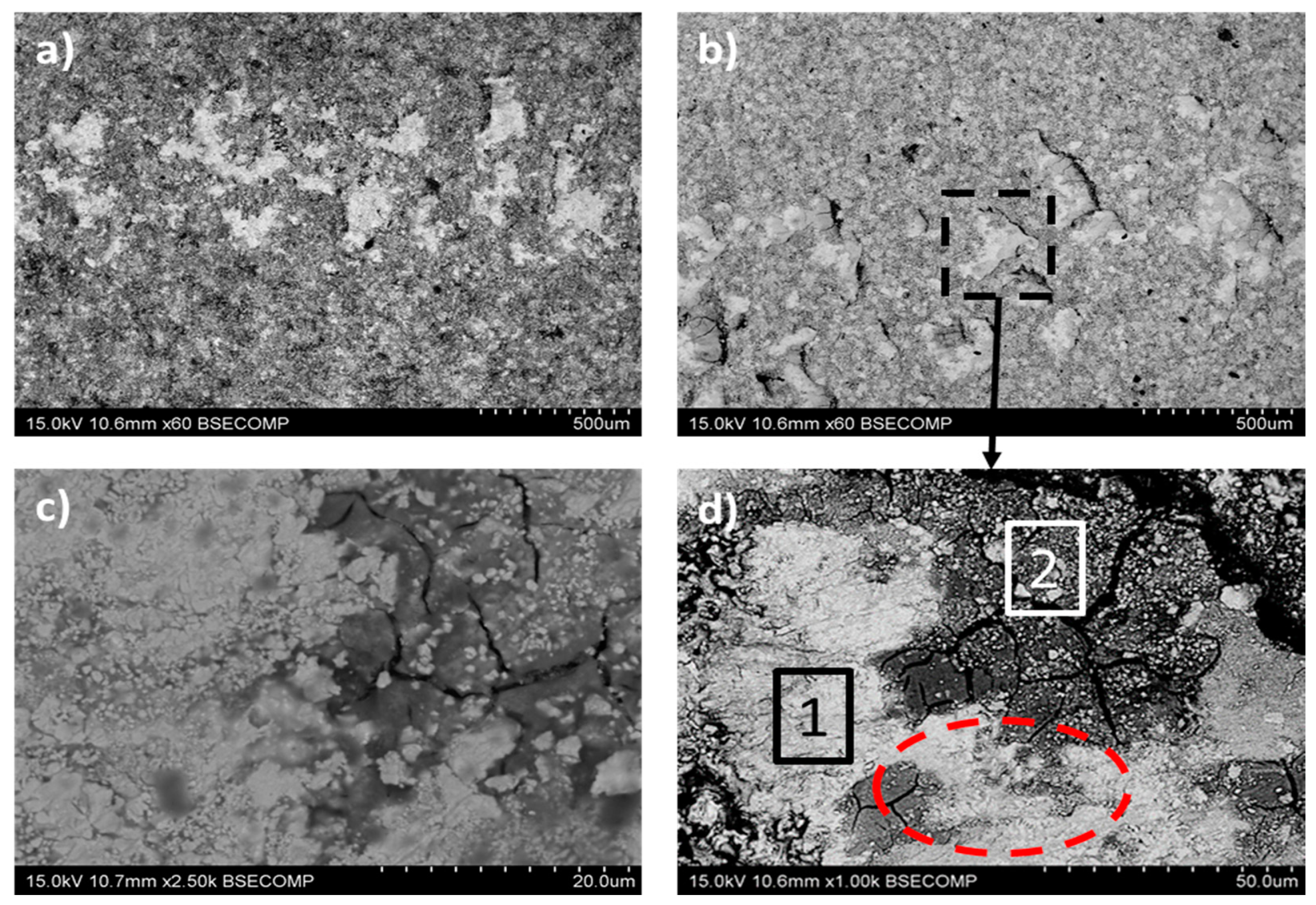
| Element | Zone 1 (wt.%) | Zone 2 (wt.%) |
|---|---|---|
| W | 78.5 | 52.0 |
| O | 6.1 | 31.5 |
| Co | 10.4 | 4.5 |
| C | 5.0 | 11.9 |
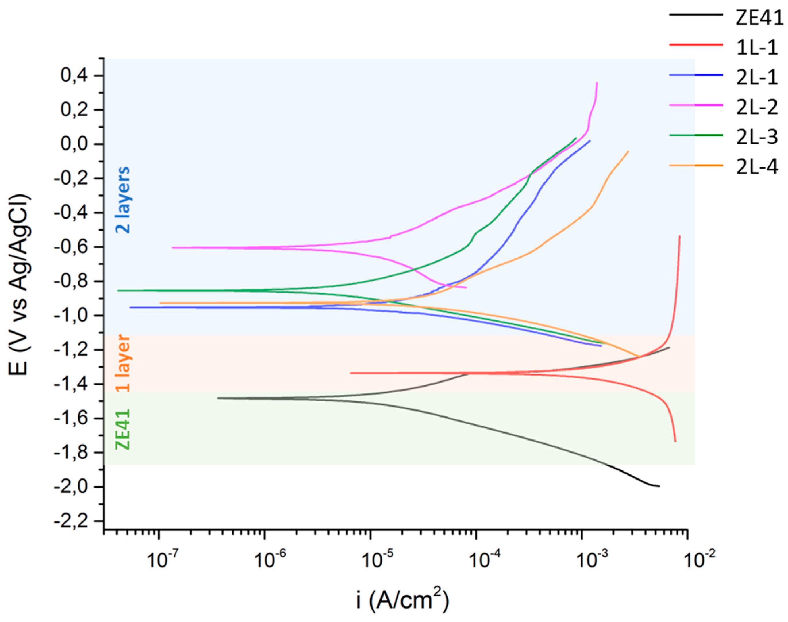
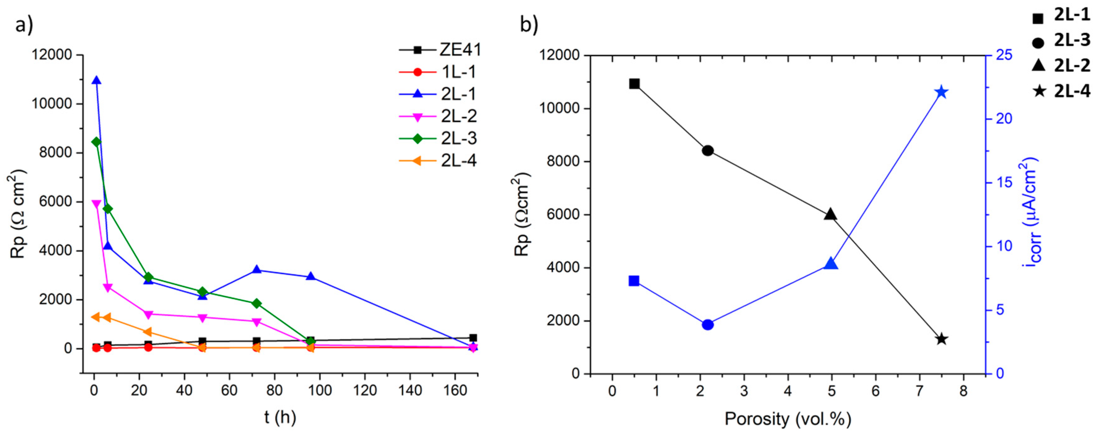
| Sample | Ecorr (V) | icorr (µA/cm2) |
|---|---|---|
| ZE41 | −1.493 | 17.9 |
| 1L-1 | −1.331 | 1250.0 |
| 2L-1 | −0.950 | 7.3 |
| 2L-2 | −0.605 | 8.6 |
| 2L-3 | −0.852 | 3.9 |
| 2L-4 | −0.922 | 22.1 |
© 2020 by the authors. Licensee MDPI, Basel, Switzerland. This article is an open access article distributed under the terms and conditions of the Creative Commons Attribution (CC BY) license (http://creativecommons.org/licenses/by/4.0/).
Share and Cite
García-Rodríguez, S.; López, A.J.; Bonache, V.; Torres, B.; Rams, J. Fabrication, Wear, and Corrosion Resistance of HVOF Sprayed WC-12Co on ZE41 Magnesium Alloy. Coatings 2020, 10, 502. https://doi.org/10.3390/coatings10050502
García-Rodríguez S, López AJ, Bonache V, Torres B, Rams J. Fabrication, Wear, and Corrosion Resistance of HVOF Sprayed WC-12Co on ZE41 Magnesium Alloy. Coatings. 2020; 10(5):502. https://doi.org/10.3390/coatings10050502
Chicago/Turabian StyleGarcía-Rodríguez, Sonia, Antonio Julio López, Victoria Bonache, Belén Torres, and Joaquín Rams. 2020. "Fabrication, Wear, and Corrosion Resistance of HVOF Sprayed WC-12Co on ZE41 Magnesium Alloy" Coatings 10, no. 5: 502. https://doi.org/10.3390/coatings10050502
APA StyleGarcía-Rodríguez, S., López, A. J., Bonache, V., Torres, B., & Rams, J. (2020). Fabrication, Wear, and Corrosion Resistance of HVOF Sprayed WC-12Co on ZE41 Magnesium Alloy. Coatings, 10(5), 502. https://doi.org/10.3390/coatings10050502