Abstract
Because of the low viscosity of high-water-based fluids, the intense wear and leakage of key friction pairs represent a bottleneck to the wide application of the high-water-based hydraulic motor in engineering machinery. In this work, based on the common characteristics of plane friction pairs, the friction experiments of a 316L stainless steel (316L)–polytetrafluoroethylene (PTFE) friction pair under various working condition were carried out by a self-designed friction experimental system with fluid lubrication. The influence of lubrication pressure and surface morphology on the 316L–PTFE friction pair was investigated both experimentally and theoretically. The experimental and numerical results indicated that increasing lubrication pressure reduced the surface wear of PTFE sample, but the leakage of 316L–PTFE friction pair also increased. It could not form an effective fluid lubrication film in the 316L–PTFE friction pair under low lubrication pressure, which caused the severe wear in friction pair interface. The smooth 316L surface could be conducive to the formation of high-water-based fluid lubrication film in 316L–PTFE friction interface. The pressure distribution of high-water-based fluid lubrication film in 316L–PTFE friction pair was also obtained in fluent. The PTFE surface was easily worn when the lubrication film in the friction pair was too thin or uneven. The friction and wear were obviously improved when the normal load was balanced by the bearing capacity of the high-water-based fluid lubrication film.
1. Introduction
Because of the special physical and chemistry properties of high-water-based fluids, the lubrication of the key friction pair was the most important technology in the development of the high-water-based hydraulic motor/pump, which significantly affected its work efficiency, performance, and service life. The poor lubrication, intense wear, and large leakage of key friction pairs in the high-water-based fluid were the bottleneck of high-water-based hydraulic motor/pump’s wider application in mining engineering, ocean engineering, and other industries [1,2]. Due to the cleanness, fire resistance, and great potential industrial application of high-water-based hydraulic motor/pump, many scholars have carried out relative research on the key friction pairs of high-water-based hydraulic motor/pump from different aspects.
In order to obtain appropriate materials matching of friction pair in water pump, Liu et al. carried out the friction experiments of slipper–swash pair with different materials on a self-designed slipper–swash plate friction system, which provided suggestions for design of friction pair with the condition of water lubrication [1]. Nie et al. studied the friction and wear behavior of the slipper–swash plate in a water axial piston motor and comprehensively analyzed the influence of swash plate angle, damping length, load carrying capacity on the lubrication, and by an experimental system of slipper–swash plate friction pair, the friction experiments of slipper–swash plate fabricated with different materials were carried out [3]. To design the piston and cylinder in water hydraulic axial piston pump, Yang et al. researched the matching of 940 stainless steel-F102 engineering plastics and 940 stainless steel-Al2O3 ceramic by experimental and theoretical analysis, which found that the ceramic and engineering plastics had excellent lubrication performance in water hydraulic transmission [4]. Strmčnik et al. studied the lubrication behavior of AISI 440C stainless steel and diamond-like carbon DLC coating for an orbital water hydraulic motor application, which significantly decreased the friction coefficient and wear of the DLC coating [5]. The lubrication of a new-type slipper friction pair in water hydraulic axial pump was analyzed by numerical simulation and theoretical analysis, which obtained the lubrication characteristics of the slipper friction pair [6]. To improve the lubrication of the sliding bearing pair in water, Yin et al. investigated the water film pressure distribution, load carrying capacity changing with radial clearance, and width–radius ratio of piston sliding bearing pair in MATLAB [7]. A piston pair with a hydrostatic bearing was presented to study the anti-sticking ability of the piston-cylinder in a water hydraulic axial pump, which improved the anti-sticking ability of the friction pair [8]. A new high-water-based radial piston motor with distribution valve groups was introduced by Qiu et al., and the friction mechanism and materials matching the slipper-crankshaft pair were investigated in a high-water-based fluid, which observed the matching of GIC coating and PEEK-30CF with more stable tribological properties [2,9]. For obtaining the suitable material matching of flow distribution plate and rotor in low-speed inner curve water hydraulic motor, Wang et al. investigated the tribological behavior of various materials (including composite materials and corrosion resistant alloy) in a seawater environment by a ring-on-disc test rig, but the lubrication film pressure in the friction interface was not taken into consideration in the experiments [10,11]. The lubrication of composite slippers in a water-based axial piston pump/motor was also investigated by a self-designed test system, and the results indicated the slipper surface polishing was necessary in pump/motor [12].
Furthermore, Olsson et al. investigated the effect of different hydraulic fluids on wear protection and friction in an inner curve radial piston hydraulic motor. They found that the wear of friction pair was increased in water with hydraulic motors operating in a low-speed application [13]. Considering the roughness, elastic deformation of piston, and pressure–viscosity effect, a numerical simulation model was established to analyze the influence of radial micro-motion on pressure distribution and abrasion, and the results indicated that the piston abrasion mainly concentrated on the hand close to piston ball [14]. The surface textures were used to improve the friction in hydraulic oil motor at low speed and high pressure, which the friction variation was significantly reduced by the surface mesh patterned textures [15]. For the wear and fatigue of friction pair in water-lubricated environment, the tribological behaviors and lubrication state were also analyzed and some effective suggestions were provided [16]. The tribological behaviors of polyethylene, synthetic rubber, and fiber resin composite polymer materials with ZCuSn10Zn2 plates were also investigated under water-lubricated conditions, which concluded the relationship between lubrication properties of polymers and their frictional noise performance [17]. The various metallic and ceramics coatings (MoS2, SiC, Si3N4, Al2O3, and ZrO2, etc.) sliding against a polyetheretherketone composite were also used to manufacture friction pair in water or oil, which provided some helpful references for the design of high-water-based hydraulic motor [18,19]. The tribological properties of a DLC coating on SUJ2 bearing steel balls in running-in process were studied by a ball-on-disk tribometer. The polishing effectively reduced the friction coefficient and inhibited the delamination of DLC coatings in water [20].
When PTFE rubbed or slid against a hard friction interface, PTFE exhibited a low coefficient of friction but a high rate of wear. The tribological behaviors of PTFE parts were closely related to the friction surface morphology [21,22]. In the high-water-based hydraulic motor/pump, the key friction pairs mainly included flow distribution plate friction pair, crankshaft–slipper pair, slipper–swash plate pair, and plunger–cylinder pair, and because of the low viscosity of water, the key friction pairs were more prone to wear and leak. Figure 1 shows the schematic of main key friction pairs in water pump/motor. As show in Figure 1a, the slipper rotated around the axis of the swash plate and produced sliding friction in the axial water-based pump/motor, in which the wear in the slipper seal area would cause components failure in hydraulic system. In Figure 1b, the slipper pushed the crankshaft to rotate and output torque in water-based radial piston motor. In low-speed conditions, the lubrication water film was more difficult to form at the slipper sliding around crankshaft outer circle. The flow distribution plate–rotor friction pair was flat on flat friction in radial inner curve low-speed motor, which was not easy to form a uniform lubricating water film. This caused more serious wear and leakage in the flow distribution plate. Taking the movement behavior of key friction pairs and the low-speed working condition into consideration in high-water-based hydraulic motor, we set up a flat–flat friction pair experimental system that can adjust the lubrication pressure in the friction interface and simulate the friction behavior of the sliding friction pair.
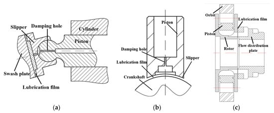
Figure 1.
The schematic of key friction pairs in water-based motor/pump: (a) slipper–swash plate; (b) slipper crankshaft friction pair; (c) the flow distribution of the plate–rotor friction pair.
Although extensive researches have been conducted on the lubrication characteristics and materials matching about the key friction pairs of high-water-based hydraulic pump/motor, the pressure of the lubricating water film depended on a damping hole or immersion in liquid. In the paper, we proposed a new experimental method to simulate the key friction pair of high-water-based hydraulic motor which the lubrication pressure of water film could be adjusted freely. The influence of lubrication pressure and surface roughness on water-lubricated friction pair was studied by material matching of 316L and PTFE, and the pressure distribution and wear mechanism of 316L–PTFE friction pair were described by a FEM model.
2. Experimental Works and Principles
The current fluid lubricated piston–roller friction pair of the inner curve hydraulic motor with hydrostatic support structure required surface fine grinding. The surface roughness had a great influence on the leakage and service life of these friction pairs. The friction pair of the flow distribution plate mostly adopted the PTFE or polymer materials (soft) and high strength alloy (hard) to ensure the friction service life and realize wear compensation. In order to study the influence of the interface roughness and lubrication pressure on the tribological behaviors of 316L–PTFE, we set up a self-designed friction experiment system. The schematic of friction pair experimental system in the paper is shown in Figure 2a. The upper sample was fixed on the piston rod and the bottom sample was fixed on the rotating plate. Under the effect of normal load, the friction surfaces of upper sample and bottom sample were pressed together. The normal load on piston rod was achieved by a gear pump (HGP-1A-F1R, Xinhong hydraulic Co., Ltd., Ningbo, China). The rotation between bottom sample and upper sample in the friction was realized by the variable frequency motor. To simulate the wear behavior of friction pair in water hydraulic motor/pump operating at low speed condition, the rotation speed of bottom sample was set to 15 r/min. The high-water-based fluid with pressure entered into the friction pair interface through the flow path on piston rod, which the lubrication pressure of high-water-based fluid was controlled by the overflow valve of water hydraulic pump (JBZ720, Suzhou Jiebao Machinery Co., Ltd., Suzhou, China). In the friction process of 316L–PTFE, the leakage of the friction pair flowed into the circular groove in the rotating disk. To record the leakage of different friction pair experiments, the leaked high-water-based fluid was collected into a measuring cup synchronously by a siphon.
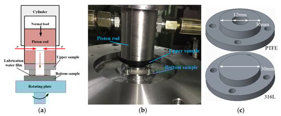
Figure 2.
(a) The schematic of flat–flat friction pair experimental system; (b) the image of friction pair experimental system; (c) the 3D model and sizes of upper sample and bottom sample.
The upper sample was black PTFE and the bottom sample was 316L stainless steel. The 3D model and size of 316L sample and PTFE sample are shown in Figure 2c. The diameter of the upper sample and bottom sample was 30 mm and the diameter of the hole in PTFE was 12 mm. The friction surfaces of the PTFE samples were polished by 2000# abrasive paper in all experiments. The friction surface of 316L sample was turned by a lathe (turning speed 800 r/min, feed rate 0.05 mm/r). In order to obtain various rough morphologies of friction surface in the 316L–PTFE friction pair experiments, the 120#, 400#, 800#, and 2000# abrasive papers were used to polish the friction surfaces of 316L samples (all 316L samples were polished for 10 min). The effects of interface lubrication pressure and roughness on the wear behavior of 316L–PTFE friction pairs were studied under room temperature (~20 °C). The experimental time of all 316L–PTFE friction pairs was half an hour. The interface morphology of the 316L–PTFE friction pair was observed by a Leica optical microscope (Leica DM4M, Leica Co., Ltd., Solms, Germany) and 3D profilometer (THINKFOCUS, SM-1000, THINKFOCUS Co., Ltd., Shanghai, China).
In Figure 3a, the 3D morphology and profile curve of the turned 316L sample are presented. The profile fluctuation of the turned 316L sample was ~4–5 μm, which was the height of turning stripes. In addition, the clear turning stripes were also observed in optical microscope (OM) image and 3D morphology. The surface morphology of PTFE sample after being polished with 2000# abrasive paper was shown in Figure 3b. The surface of PTFE sample was smooth, which the profile fluctuation (1.5 μm) was far less than that of the turned 316L sample. The high-water-based fluid in the study was fully emulsified with 95% pure water and 5% mineral hydraulic oil. To remove the stain and residues in the experiments, the holes in the piston rod and all samples were cleaned with alcohol by an ultrasonic method.
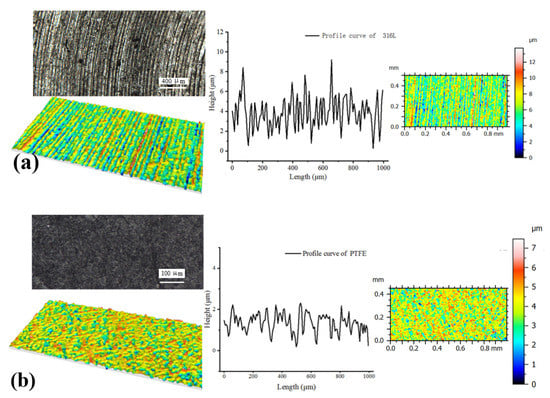
Figure 3.
The morphology and profile curves of turned 316L and PTFE: (a) turned 316L sample, (b) PTFE sample.
3. Results and Discussion
3.1. The Influence of Lubrication Pressure on the Tribological Behaviors of the 316L–PTFE Friction Pair
In the water-lubricated sliding friction pair, the pressure of the fluid lubrication film was an important factor affecting the lubrication performance of the friction pair. The inlet pressure of the fluid lubrication film in a commonly used slipper friction pair was obtained by damping hole. The diameter and length of damping hole determined the lubrication behavior of fluid lubrication film in the hydrostatic bearing slipper. In order to study the influence of the lubrication pressure of the fluid lubrication film on the wear behavior of the sliding friction pair, we carried out the friction experiment of 316L–PTFE with different pressures in a high-water-based environment. In the experiments, all bottom samples were 316L turning with same parameter, and the upper samples were the PTFE polishing with 2000# abrasive paper.
As shown in Figure 4a, the normal load acting on piston rod was the load on 316L–PTFE friction pair, and the pressure in cylinder was 1.5 MPa (the diameter of piston rod was 50 mm; the normal load was ~2700 N). Because of structural characteristics of gear pump, the pressure in the cylinder had a fluctuation of ~0.15 MPa. The different lubrication pressure curves of the high-water-based fluid in the friction pair interface are presented in Figure 4b. The friction experiments were divided into five groups with lubrication pressure ranging from 4 to 12 MPa. Because of the characteristics of the triplex piston water pump, there were some fluctuations in the lubrication pressure of the high-water-based fluid.
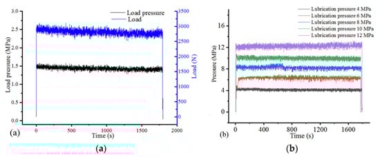
Figure 4.
(a) The normal load on piston rod; (b) the lubrication pressure curves of high-water-based fluid in friction pairs.
The friction morphology of the 316L sample after friction with the PTFE sample is presented in Figure 5 when the lubrication pressure of high-water-based fluid was 4 MPa. The original turning patterns of 316L sample were basically unchanged in the OM images, which indicated that the surface wear of 316L sample was small. However, the black materials were observed in turning grooves in the high-magnification OM images. Compared with the micrographs of original 316L surface, it was known that the turning patterns on original 316L surface were clean, whereas black materials were found in the turning grooves after friction. We deduced that the black material that filled in the turning grooves of the 316L sample was ground from the PTFE surface during friction process.
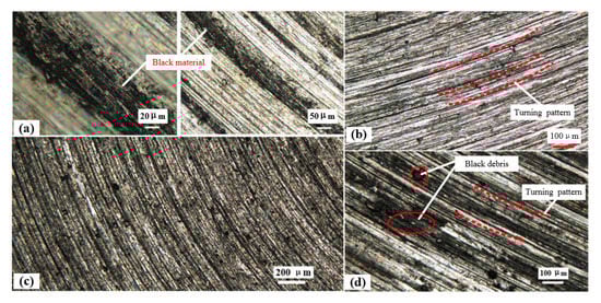
Figure 5.
The surface morphology of 316L after friction with lubrication pressure of 4 MPa: (a) the morphology of the 316L sample after friction; (b) the original morphology of the 316L sample; (c,d) the morphology of the 316L sample in different magnification after friction.
Figure 6 shows the OM images and 3D morphology of the PTFE sample after friction with the 316L sample. Many deep circular wear marks were directly observed in the PTFE sample surface. Under the effect of normal load on friction pair, the PTFE surface generated the plough friction, which caused the original PTFE surface to be severely damaged. In Figure 6a, the wear debris of 316L embedded in PTFE surface are also observed, as well as the deep and large wear marks formed on PTFE sample surface in the 3D morphology. The wear morphology of the friction interface indicated that the high-water-based lubrication film was not formed in 316L–PTFE friction pair effectively. The turning surface of 316L sample directly produced sliding friction on PTFE surface, because of the small yield stress of PTFE (26 MPa), which caused PTFE material to fall off upper sample surface in friction process. The morphology of worn PTFE surface was corresponding to the morphology of 316L sample in Figure 5.
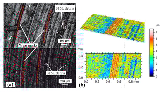
Figure 6.
(a) The optical microscope (OM) morphology of the PTFE sample after friction with lubrication pressure of 4 MPa; (b) the 3D morphology of the PTFE sample after friction with lubrication pressure of 4 MPa.
The friction morphology of 316L–PTFE friction pair under the lubrication pressure of 12 MPa is provided in Figure 7. Compared with the original turning surface of the 316L sample, the original morphology and turning grooves of the 316L sample still remained unchanged after the friction experiment. Meanwhile, the black PTFE wear debris was not found in the 316L turning grooves. Figure 7c–e shows the corresponding OM images and 3D morphology of the PTFE sample after the friction experiment. It found that no obvious large and deep wear marks appeared in friction interface and the morphology of PTFE sample remained unchanged after friction. The friction morphology of 316L–PTFE friction pair indicated that, under the lubrication pressure of 12 MPa, an effective high-water-based lubrication film formed in the friction interface which avoided the sliding friction contact between 316L and PTFE.
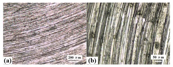
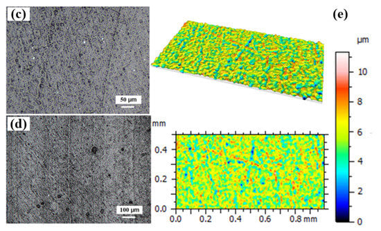
Figure 7.
(a,b) The OM morphology of the 316L sample after friction with lubrication pressure of 12 MPa; (c–e) the OM images and 3D morphology of worn PTFE after friction with lubrication pressure of 12 MPa.
Figure 8 shows the surface profile curves of PTFE and 316L after friction with different lubrication pressures. The friction and wear behaviors of the 316L–PTFE friction pair under different lubrication pressures were analyzed by profile curves and roughness of friction interface. As shown in Figure 8a, the profile curves of turned 316L sample and the PTFE sample polished by 2000# abrasive paper were provided. The profile of original 316L surface fluctuated periodically due to turning pattern, while the PTFE sample surface was smooth. In Figure 8b, the profile curve of 316L surface did not change much under lubrication pressure of 4 MPa, but the profile of PTFE surface changed greatly. The PTFE sample surface formed a deep wear mark with depth ~10 μm and the profile fluctuation was far greater than the original PTFE surface, which was consistent with the wear morphology in Figure 6. In Figure 8c, under the lubrication pressure of 6 MPa in friction pair, the profile curve of PTFE surface reflected that friction surface of PTFE sample also generated great wear after friction pair experiment. In Figure 8d, with the increasing of lubrication pressure, the profile fluctuation of PTFE sample was decreased at lubrication pressure of 8 MPa, but the PTFE surface still produced a certain wear. Because of high yield stress and hardness of 316L, the wear mainly generated on PTFE surface in friction process while the surface morphology of 316L still remained original morphology. The profile curves of PTFE and 316L after friction under lubrication pressures of 10 and 12 MPa are shown in Figure 8e,f. The profile curve of the frictional PTFE sample was similar to that of the original PTFE sample, and the obvious wear marks did not observed. The profile curves and morphology of friction pair under lubrication pressure of 10 and 12 MPa indicated that the high-water-based lubrication film effectively avoided severe friction and wear in 316L–PTFE friction interface.
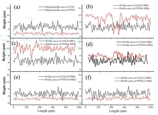
Figure 8.
The profile curves of 316L sample and PTFE sample after friction experiments: (a) the original profile curves; (b) the lubrication pressure of 4 MPa; (c) the lubrication pressure of 6MPa; (d) the lubrication pressure of 8 MPa; (e) the lubrication pressure of 10 MPa; (f) the lubrication pressure of 12 MPa.
The surface roughness and leakage of 316L–PTFE friction pair after friction experiment were given in Figure 9. Under the lubrication pressure of 4 MPa, the roughness of PTFE surface was the largest (Ra = 1.85 μm) after friction experiment, while the roughness of the 316L sample had a slight reduction. The PTFE surface was severely worn at lubrication pressure of 4 MPa. The wear debris of PTFE was embedded into turning grooves in friction process which caused the reduction in the roughness of 316L. In addition, the leakage of the 316L–PTFE friction pair was almost zero, which indicated that no high-water-based film was formed in the friction pair. The surface wear of PTFE sample was still serious when the lubrication pressure was 6 MPa in friction interface. The roughness of PTFE friction surface was increased from Ra 0.2 μm to Ra 1.3 μm. The leakage of the 316L–PTFE friction pair in half an hour was only ~103 mL, which indicated that the extreme thin and uneven lubrication film formed in 316L–PTFE friction interface. However, the uneven high-water-based lubrication film was not enough to support the normal load acting on friction pair. The direct contact between 316L and PTFE in sliding friction would damage the friction interface. With the increasing of lubrication pressure, the surface roughness of PTFE decreased after friction experiment which demonstrated that the lubrication effect in friction pair was improved, but the leakage of 316L–PTFE friction pair also increased.
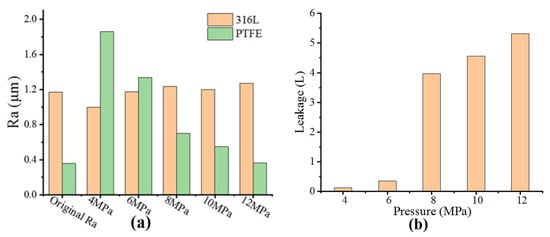
Figure 9.
(a) The average roughness (Ra) of 316L and PTFE after friction experiments; (b) the leakages of the friction pairs with different lubrication pressures.
When the lubrication pressure in friction interface was 8 MPa, the friction and wear of PTFE sample were relieved. The surface roughness of PTFE and leakage were Ra = 1.5 μm and 2.6 L, respectively. The friction pair interface formed fluid lubrication film, but the micro structures on 316L and PTFE would penetrate the lubrication film and produce sliding friction. The roughness and surface morphology of friction pair basically changed little, and no obvious wear marks were observed under lubrication pressure of 10 and 12 MPa. The roughness of the PTFE sample was consistent with the morphology observed in Figure 7. The high-water-based lubrication film was effective in the friction interface when the lubrication pressure was high enough. However, the large leakage in 316L–PTFE friction pair at high lubrication pressure was also an unavoidable problem.
3.2. The Influence of Surface Roughness on Tribological Behavior of 316L–PTFE Friction Pair
Because of the very thin fluid lubrication film, the roughness and morphology of the friction surface had a great influence on pressure distribution and lubrication performance. In order to investigate the influence of interface roughness on friction and wear behavior of 316L–PTFE friction pair, we carried out the friction experiments of 316L (with different surface roughness) and PTFE (polished by 2000# abrasive paper) under the same load and lubrication pressure.
In Figure 10a, the load pressure on piston rod during the experiment was 1.5 MPa, and the lubrication pressure of high-water-based fluid in 316L–PTFE friction interface was 8 MPa. The average roughness of 316L after polishing with different abrasive papers was shown in Figure 10b. The 316L sample had the minimum roughness (Ra = ~0.2 μm) after polishing with 2000# abrasive paper. The roughness of 316L sample polished with 120# abrasive paper was Ra = ~0.9 μm, and the roughness of original turning 316L sample surface was Ra = 1.1 μm. The effect of roughness on friction behavior of 316L–PTFE friction pair was studied in the self-designed experimental system.
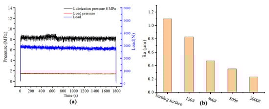
Figure 10.
(a) The load curve and lubrication pressure of 316L–PTFE friction pair; (b) the average roughness (Ra) of polished 316L surface with various abrasive papers.
The friction morphologies of the 316L sample polished by 120# abrasive paper and the PTFE sample are shown in Figure 11. Figure 11a showed the original morphology of the 316L sample polished by 120# abrasive paper, which distributed many rough stripes on 316L sample surface. In Figure 11b, the friction morphology of the 316L sample indicated that the obvious circle friction area was generated on friction surface. The 316L sample friction surface became dark, which seemed to cover a layer of black material. We deduced that the material on PTFE sample surface was ground down by the rough structures of 316L in friction process. In Figure 11c, the 3D morphology of 316L friction surface also proved the surface morphology change and the similar circle wear area on friction surface was also observed. Figure 11d,e shows the OM images and 3D morphology of the PTFE sample friction with 316L sample (polished by 120# abrasive paper). The deep wear marks and 316L wear debris on PTFE surface indicated that the water lubrication film cannot support the load on friction pair well. Both friction surfaces were in direct contact and the sliding friction of 316L–PTFE friction pair occurred. Because of the lower hardness and yield stress of PTFE, the microstructure on the 316L sample surface easily penetrated into the soft PTFE surface in the sliding process, which generated plough friction and formed deep wear marks. The inhomogeneous of high-water-based lubrication film in thickness caused local wear in PTFE sample.
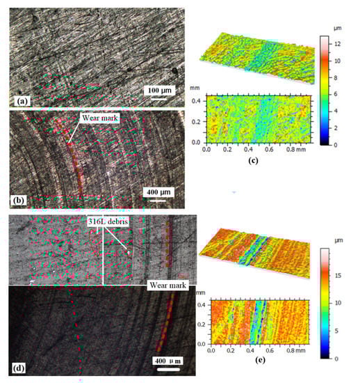
Figure 11.
(a) The original morphology of the 316L sample polished by 120# abrasive paper; (b,c) the OM images and 3D morphology of 316L sample after friction experiment; (d,e) the OM images and 3D morphology of the PTFE sample after friction experiment.
The OM images and 3D morphology of 316L sample (polished by 2000# abrasive paper) and PTFE sample were shown in Figure 12. Figure 12a–c shows the OM images and 3D morphology of 316L surface after friction pair experiment. The PTFE debris was not observed on 316L surface and the 3D morphology of 316L sample was still smooth. Comparing to the original morphology of PTFE sample, the friction morphology of PTFE in Figure 12d–f indicated that the friction interface was basically not damaged in friction process. The PTFE surface only generated some shallow wear marks. With the increasing of surface smoothness of the 316L sample, the surface wear of PTFE sample was greatly improved. It summarized that the lower roughness of friction interface could effectively reduce the wear in 316L–PTFE friction interface. The smooth friction surface was good for the lubrication film forming in friction pair which avoided the direct contact and sliding friction between 316L and PTFE.
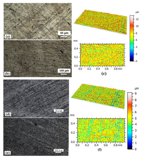
Figure 12.
(a–c) The morphology of 316L sample (polished by 2000# abrasive paper) after friction experiment; (d–f) the OM images and 3D morphology of PTFE sample after friction experiment.
The profile curves of the 316L–PTFE friction pairs after friction experiments under different roughness are given in Figure 13. The profile curves of PTFE sample surface had great fluctuation when the 316L samples were polished by 120# and 400# abrasive paper, which produced wear marks on PTFE surface. However, after polishing the friction surface of the 316L samples with 800# and 2000# abrasive paper, the profile curves of PTFE were stable and without high fluctuation after friction. Especially, in the PTFE sample surface friction with the 316L sample polished by 2000# abrasive paper, the friction profile of PTFE sample was basically similar to the original surface morphology in Figure 3. The results showed that the lower surface roughness was beneficial to forming lubrication film in friction interface under same lubrication pressure of 8 MPa. The high-water-based lubrication film effectively reduced the wear in friction pair when the friction interface was smooth.
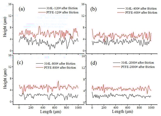
Figure 13.
The profile curves of 316L sample and PTFE sample after friction experiments under lubrication pressure of 8 MPa: (a) the 316L sample polished by 120# abrasive paper; (b) the 316L sample polished by 400# abrasive paper; (c) the 316L sample polished by 800# abrasive paper; (d) the 316L sample polished by 2000# abrasive paper.
The surface roughness and leakage of the 316L–PTFE friction pair after the friction experiment with different interface morphologies are shown in Figure 14. The surface roughness of 316L sample did not change much after friction with PTFE sample. The 316L sample polished by 2000# abrasive paper was Ra = ~0.32 μm after friction. Compared with the 316L (turning surface)–PTFE friction pair, the roughness of PTFE sample (friction with the 316L sample polished by 120# abrasive paper) was decreased to Ra 0.79 μm. With the decreasing of 316L surface roughness, the Ra of PTFE sample surface was also decreased after friction experiment, which indicated the smooth friction interface was more conducive to form lubrication film. Under the same load and lubrication pressure on 316L–PTFE friction pair, the rough friction surface caused more leakage in friction pair. The leakage of turning 316L–PTFE friction pair was 4.06 L and the leakage of 316L (polished by 2000# abrasive paper)-PTFE friction pair was 1.76 L in half an hour. The rough surface not only caused more leakage of the friction pair, but also led to wear in the friction interface.
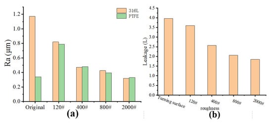
Figure 14.
(a) The average roughness (Ra) of 316L–PTFE friction pairs after friction experiments; (b) the leakages of 316L–PTFE friction pairs with different interface roughness.
3.3. The Lubrication Mechanism and Wear Behavior of the 316L–PTFE Friction Pair
In order to investigate the pressure-flow characteristics, pressure distribution, and bearing capacity of high-water-based lubrication film, we analyzed the mechanical model of the 316L–PTFE friction pair. In fluid simulation software FLUENT, a fluid simulation model of the 316L–PTFE friction pair was established to describe the pressure distribution, bearing capacity, and lubrication characteristics. The friction contact model of 316L–PTFE in friction process was analyzed by a FEM model in ANSYS which calculated the contact stress and plastic strain in friction interface.
The schematic of 316L–PTFE friction pair (parallel disk damper) in the paper was shown in Figure 15. The high-water-based fluid entered from the hole and flowed through the damper interface of two parallel disks to form a lubrication film, which the direct contact and sliding friction between 316L sample and PTFE sample were avoided. The relationship between pressure and flow characteristic (flow Q) of parallel disk friction pair (316L–PTFE friction pair) was described as the following formula,
where the ∆p denotes pressure between the inlet and outlet of parallel disk damper. Ce denotes the correction coefficient, and h denotes the thickness of lubrication film in friction interface. D denotes the outer diameter of friction pair and d denotes the inner diameter of friction pair. μ denotes the kinetic viscosity of the high-water-based fluid.
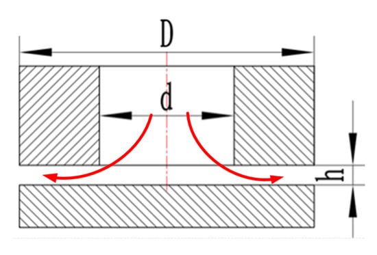
Figure 15.
The schematic of 316L- PTFE friction pair (parallel disk damper).
This formula was used to deduce the pressure distribution in the radial direction of damper:
The bearing capacity of fluid lubrication film W1:
Taking Equation (2) into the above formula to calculate the W1:
The all bearing capacity (W) of 316L–PTFE friction pair:
According to the leakages of the 316L–PTFE friction pair recorded in Figure 9b, the thickness of fluid lubrication film could be calculated by taking the leakage into the Equation (1). We simulated the pressure distribution of high-water-based fluid lubrication film under different lubrication pressures (8, 10, 12 MPa) in Fluent software, which the pressure distribution images of lubrication film in 316L–PTFE friction pair interface were shown in Figure 16. In Figure 16a, it could be seen that the pressure distribution of lubrication film decreased along the radial direction of friction pair. The data of different lubricating film pressures along the radial distribution hole were extracted and displayed in Figure 16b. With the increasing of lubrication pressure, the pressure decayed rapidly in radial direction of the damping gap. The bearing capacity of the high-water-based lubrication film was calculated by the Equation (5). The bearing capacity of high-water-based lubrication film was ~1300 N when the lubrication pressure was 4 MPa, which could not support the normal load on friction pair (~2700 N). With the increasing of lubrication pressure, the bearing capacity of the high-water-based lubrication film reached about 2600 N at lubrication pressure of 8 MPa. When the load on the 316L–PTFE friction pair was balanced by the bearing capacity of high-water-based lubrication film, the effective lubrication film could form in 316L–PTFE friction pair.
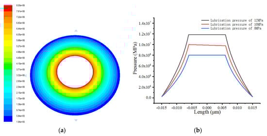
Figure 16.
(a) The pressure distribution image of high-water-based lubrication film in friction pair, (b) the pressure distribution on the radial direction.
In order to study the influence of surface morphology on the friction and wear behavior of 316L–PTFE friction pair, we simulated the pressure distribution and plastic strain of lubrication film between the smooth PTFE and rough turning 316L. Figure 17 showed the pressure distribution images of lubrication film in rough friction interface and smooth friction interface. It can be seen from the Figure 17a that the pressure distribution in the direction of lubrication film thickness conformed to laminar flow characteristics. In Figure 17b, the turning surface with periodic bulge had significant influence on the thickness of lubrication film. The pressure distribution and flow field near the turning surface was uneven and unstable. Therefore, the flow field of lubrication film on the smooth interface of friction pair was more stable which was easier to form the fluid lubrication film. The rough turning profile on 316L generates greater resistance and fluctuation to form high-water-based lubrication film. Under the same load and lubrication condition, the wear of PTFE sample in smooth friction pair interface was far smaller than that of the rough friction pair.
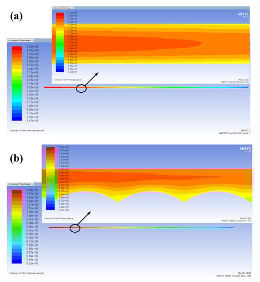
Figure 17.
(a) The pressure distribution on smooth parallel disk damping gap, (b) the pressure distribution on turning parallel disk damping gap.
In the FEM analysis software ANSYS, we established the contact model of PTFE and 316L to simulate the friction process. The turning patterns of the 316L sample were simplified into round fringe bulges. The stress and plastic strain distribution in the friction pair interface were obtained. The materials properties of PTFE and 316L in the FEM simulation were given in Table 1.

Table 1.
The material properties of 316L stainless steel and PTFE.
The lubrication pressure could not support the load on friction pair when the high-water-based fluid was 4 MPa. There was no lubrication film formed on the friction interface. Under the effect of normal load (~2700 N) on friction pair, the PTFE sample was pressed on the turned 316L sample surface, which produced sliding friction and wear in friction pair. Figure 18 showed the stress and plastic strain distribution results of friction pair in sliding process. According to the stress distribution image of PTFE-316L, the maximum contact stress of the friction pair was 167 MPa (less than the yield strength of 316L). The stress distribution state of the PTFE sample in Figure 18b indicated that the maximum surface stress of the PTFE sample in friction process was about 31 MPa, which exceeded the yield strength of PTFE. In Figure 18c,d, it can be seen that the equivalent plastic strain was mainly concentrated on the PTFE friction surface. The equivalent plastic strain of 316L sample was very small and the maximum equivalent plastic strain (0.64) located in PTFE sample surface. Actually, the micro-turning patterns on 316L surface were not regular arc-shaped bulge, as the turning 316L profile curve shown in Figure 3a, the real surface profile had many sharp corners. In the actual friction process of 316L and PTFE, the contact stress was far greater than that of calculated in Figure 18. Therefore, the friction surface of the PTFE sample would generate severely damage and wear after friction experiment.
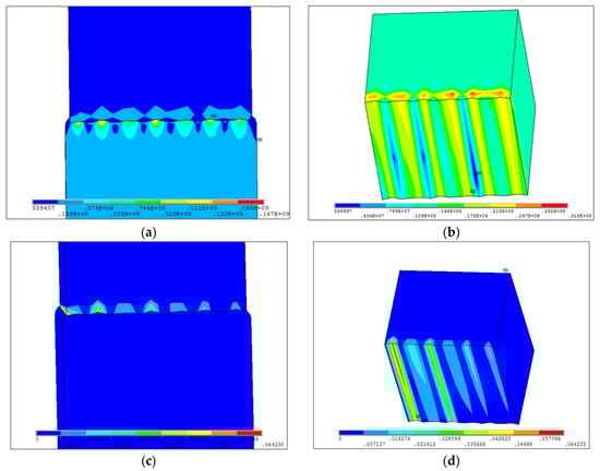
Figure 18.
(a) The pressure distribution of 316L–PTFE friction pair in friction process; (b) the pressure distribution in PTFE friction surface; (c) the equivalent plastic strain distribution of 316L–PTFE friction pair; (d) the equivalent plastic strain distribution in the PTFE friction surface.
4. Conclusions
In this work, the tribological behaviors of the 316L–PTFE friction interface were investigated on a friction experimental system with fluid lubrication. The influence of lubrication pressure and interface roughness on the wear of friction surface was studied by experimental method. By use of FEM analysis softwares FLUENT and ANSYS, the pressure distribution of the fluid lubrication film and the wear mechanism in friction interface were also investigated. Combining experiments and theoretical analysis, we obtained the following important conclusions from this work:
- In turned 316L friction with PTFE sample, the higher lubrication pressure in friction interface reduced surface wear of PTFE sample, but the leakage of 316L–PTFE friction pair increased with the lubrication pressure. The friction pair interface could not form high-water-based lubrication film at the lubrication pressure of 4 and 6 MPa, which led to serious wear on PTFE sample surface.
- With the decreasing of roughness in the friction interface, the wear of PTFE surface was greatly relieved in the same lubrication and load condition. The leakage of 316L–PTFE friction pair was also reduced when the friction interface was smooth.
- The leakage model of 316L–PTFE friction pair was analyzed by numerical simulation. The increasing of lubrication pressure would enhance the bearing capacity of high-water-based lubrication film. The pressure was decreasing in radial direction of friction pair, and the distribution rule of lubrication pressure was obtained. The friction interface directly produced sliding friction and generated great contact stress when the lubrication film could not support the load on friction pair. The micro-morphology of the friction interface had a great influence on the pressure distribution and flow field in the direction of lubrication film thickness.
Author Contributions
Conceptualization, J.M. and J.Z.; methodology, J.M. and H.Y.; software, L.S.; validation, J.M., J.Z. and L.S.; formal analysis, H.Y.; investigation, J.M. and L.S.; resources, J.Z.; data curation, H.Y. and L.S.; writing—original draft preparation, J.M. and J.Z.; writing—review and editing, H.Y. and L.S.; visualization, J.M.; supervision, J.Z.; project administration, J.M.; funding acquisition, J.Z. All authors have read and agreed to the published version of the manuscript.
Funding
This research was funded by the National Natural Science Foundation of China (No. 51675519), Science and Technology Program of Xuzhou City (KC19001) and a Project Funded by the Priority Academic Program Development of Jiangsu Higher Education Institutions (PAPD).
Conflicts of Interest
The authors declare no conflict of interest.
References
- Yinshui, L.; Wu, D.; He, X.; Zhuangyun, L. Materials screening of matching pairs in a water hydraulic piston pump. Ind. Lubr. Tribol. 2009, 61, 173–178. [Google Scholar] [CrossRef]
- Qiu, B.; Zhao, J.; Man, J. Comparative study of materials for friction pairs in a new high water-based hydraulic motor with low speed and high pressure. Ind. Lubr. Tribol. 2019, 71, 164–172. [Google Scholar] [CrossRef]
- Nie, S.L.; Huang, G.H.; Li, Y.P. Tribological study on hydrostatic slipper bearing with annular orifice damper for water hydraulic axial piston motor. Tribol. Int. 2006, 39, 1342–1354. [Google Scholar] [CrossRef]
- Huayong, Y.; Jian, Y.; Hua, Z. Research on materials of piston and cylinder of water hydraulic pump. Ind. Lubr. Tribol. 2003, 55, 38–43. [Google Scholar] [CrossRef]
- Strmčnik, E.; Majdič, F.; Kalin, M. Water-lubricated behaviour of AISI 440C stainless steel and a DLC coating for an orbital hydraulic motor application. Tribol. Int. 2019, 131, 128–136. [Google Scholar] [CrossRef]
- Huanlong, L.; Jian, K.; Guozhi, W.; Lanying, Y. Research on the lubrication characteristics of water hydraulic slipper friction pairs. Proc. Inst. Mech. Eng. Part C J. Mech. Eng. Sci. 2006, 220, 1559–1567. [Google Scholar] [CrossRef]
- Yin, F.; Nie, S.; Zhang, Z.; Zhang, X. Research on the sliding bearing pair of water hydraulic axial piston pump. Proc. Inst. Mech. Eng. Part C J. Mech. Eng. Sci. 2013, 227, 2049–2063. [Google Scholar] [CrossRef]
- Huanlong, L.; Guozhi, W.; Jian, K.; Lanying, Y. Research on the anti-sticking characteristics of water hydraulic piston friction pairs with hydrostatic bearing. Lubr. Sci. 2013, 25, 453–462. [Google Scholar] [CrossRef]
- Qiu, B.; Zhao, J.; Zhao, L. Characterization and performance analysis of a new type of a high water-based hydraulic motor with a self-balanced distribution valve mode. Proc. Inst. Mech. Eng. Part C J. Mech. Eng. Sci. 2017, 231, 4655–4669. [Google Scholar] [CrossRef]
- Wang, Z.; Gao, D. Comparative investigation on the tribological behavior of reinforced plastic composite under natural seawater lubrication. Mater. Des. 2013, 51, 983–988. [Google Scholar] [CrossRef]
- Wang, Z.; Gao, D. Friction and wear properties of stainless steel sliding against polyetheretherketone and carbon-fiber-reinforced polyetheretherketone under natural seawater lubrication. Mater. Des. 2014, 53, 881–887. [Google Scholar] [CrossRef]
- Li, K.Y.; Hooke, C.J. A note on the lubrication of composite slippers in water-based axial piston pumps and motors. Wear 1991, 147, 431–437. [Google Scholar] [CrossRef]
- Olsson, H.; Ukonsaari, J. Wear testing and specification of hydraulic fluid in industrial applications. Tribol. Int. 2003, 36, 835–841. [Google Scholar] [CrossRef]
- Xu, B.; Zhang, J.; Yang, H.; Zhang, B. Investigation on the radial micro-motion about piston of axial piston pump. Chin. J. Mech. Eng. 2013, 26, 325–333. [Google Scholar] [CrossRef]
- Pettersson, U.; Jacobson, S. Textured surfaces for improved lubrication at high pressure and low sliding speed of roller/piston in hydraulic motors. Tribol. Int. 2007, 40, 355–359. [Google Scholar] [CrossRef]
- Spikes, H.A. Wear and fatigue problems in connection with water-based hydraulic fluids. J. Synth. Lubr. 1987, 4, 115–135. [Google Scholar] [CrossRef]
- Dong, C.; Shi, L.; Li, L.; Bai, X.; Yuan, C.; Tian, Y. Stick-slip behaviours of water lubrication polymer materials under low speed conditions. Tribol. Int. 2017, 106, 55–61. [Google Scholar] [CrossRef]
- Yin, F.; Ji, H.; Nie, S. Tribological behavior of various ceramic materials sliding against CF/PTFE/graphite-filled PEEK under seawater lubrication. Proc. Inst. Mech. Eng. Part J J. Eng. Tribol. 2019, 233, 1729–1742. [Google Scholar] [CrossRef]
- Zhao, J.; He, Y.; Wang, Y.; Wang, W.; Yan, L.; Luo, J. An investigation on the tribological properties of multilayer graphene and MoS2 nanosheets as additives used in hydraulic applications. Tribol. Int. 2016, 97, 14–20. [Google Scholar] [CrossRef]
- Niiyama, Y.; Shimizu, N.; Kuwayama, A.; Okada, H.; Takeno, T.; Kurihara, K.; Adachi, K. Effect of running-in for delamination and friction properties of self-mating diamond-like carbon coatings in water. Wear 2017, 378, 27–34. [Google Scholar] [CrossRef]
- Biswas, K.; Vijayan, K. Friction and wear of ptfe—A review. Wear 1992, 158, 193–211. [Google Scholar] [CrossRef]
- Sawyer, W.G.; Freudenberg, K.D.; Bhimaraj, P.; Schadler, L.S. A study on the friction and wear behavior of PTFE filled with alumina nanoparticles. Wear 2003, 254, 573–580. [Google Scholar] [CrossRef]
© 2020 by the authors. Licensee MDPI, Basel, Switzerland. This article is an open access article distributed under the terms and conditions of the Creative Commons Attribution (CC BY) license (http://creativecommons.org/licenses/by/4.0/).