Article

Investigation and Prediction on Regulation of Hydrophobicity of Polymethyl Methacrylate (PMMA) Surface by Femtosecond Laser Irradiation

1
College of Mechanical Engineering, Jiangsu University, Zhenjiang 212013, China
2
College of Mechanical Engineering, Suzhou University of Science and Technology, Suzhou 215009, China
3
School of Electromechanical Engineering, Guangdong University of Technology, Guangzhou 510006, China
*
Author to whom correspondence should be addressed.
Coatings 2020, 10(4), 386; https://doi.org/10.3390/coatings10040386
Submission received: 12 March 2020 / Revised: 11 April 2020 / Accepted: 13 April 2020 / Published: 15 April 2020
(This article belongs to the Section Surface Characterization, Deposition and Modification)

Abstract

:
This study presents the contact angle prediction model of a trapezoidal groove structure based on the laser irradiation on polymethyl methacrylate (PMMA). The trapezoidal groove structure was designed and proposed according to the characteristics of a femtosecond laser. First, the complete wetting model and incomplete wetting model which were compatible with the characteristics of the laser mechanism were constructed based on the Gibbs free energy and the structural parameters of the trapezoidal groove structure. Then, based on the contact angle prediction models constructed, the samples were divided into two groups according to the designed structural parameters, and the experimental investigations were carried out. The result demonstrated that the incomplete wetting prediction model was more in line with the actual situation. The convex width and the top edge length of spacing of the trapezoidal groove structure both affected the contact angle prediction results. From both the experimental contact angles and the contact angles predicted by the incomplete wetting model, it could be known that the contact angle reached 138.09° when the ratio of the convex width to the top edge length of spacing was 0.25, indicating that the smaller the ratio of the convex width to the top edge length of spacing, the better the hydrophobicity of PMMA.

1. Introduction

Biomimetic interfaces such as water strider leg and the lotus leaf have been widely concerned for self-cleaning, dustproof and anticorrosive properties [1]. Such self-cleaning surfaces are called hydrophobic surfaces in the research community. A hydrophobic surface refers to a surface that can hardly be moistened by droplets, and its contact angle with water is not less than 90° [2,3]. At present, researchers have made continuous efforts in exploring the preparation of hydrophobic surface [4]. There are mainly two approaches to construct hydrophobic structures, one is making the surface of the material have low surface energy and the other is machining micro-nanoscale topologies on the surface of material [5,6].
Many methods have been proposed for preparing hydrophobic structures. Razavi et al. [7]. used chemical vapor deposition to make microstructures on the surface of copper. Although various chemical methods have been widely used in the construction of hydrophobic structures, the properties of the micro-nano structures constructed by chemical methods are random and the arrangement of the structures cannot be controlled manually, which greatly influences the prediction of the hydrophobicity of materials. Song et al. [8] used micro-milling to fabricate the microstructure on PMMA. The properties of the as-fabricated microstructures are usually affected by the machine tool, resulting in the uncontrollable size of the structure [9]. Wang et al. [10] used ion etching to fabricate T-shaped micro array structures with different densities and sizes on the surface of silicon wafers. Chen et al. [11] developed a rapid one-step electrodepositing process to fabricate superhydrophobic cathodic surface on copper plate in the electrolytic solution containing nickel chloride, myristic acid and ethanol. However, the applications of these methods are limited due to their high cost, complicated process and large time consumption [12]. At present, the above processing methods of superhydrophobic structures have been widely used, but they are not so effective in exploring the rule of the contact angle.
With the development of micro/nano-fabrication technology, laser processing technology has been gradually applied to the processing of micro-nano structure. Chichkov et al. [13] drilled the surface of the steel with femtosecond laser, picosecond laser and nanosecond laser, respectively. It can be found that the core mechanism of material removal under long-pulse laser irradiation is thermal deposition, resulting in melts on the edge of the structure after processing. Zorba et al. [14] used a femtosecond laser to tailor the wetting response of silicon surfaces. Zhu et al. [15] used a laser to process composite materials and found that long pulse laser processing led to a significant heat affected zone, and that the heat accumulation would cause over-burning if the actuation duration between the laser and material was too long. However, the femtosecond lasers can directly convert materials from solid to gaseous state. When the laser frequency is lower than the critical frequency, thermal conduction has not occurred to remove the material of surface due to the extremely short pulse time. After laser irradiation, the material will rapidly cool down while the surface state changes, which has the least thermal impact on the processing point [16]. In contrast, when the laser frequency is higher than the critical frequency, the thermal decomposition of the surface of the polymer material is the main removal mechanism, the heat effect of the material is small, and the processed surface is smooth. Riveiro et al. [17] investigated the CO2 laser (λ = 10,600 nm) texturing of PTFE surfaces. Qin et al. [18] used the picosecond UV laser (λ = 355 nm) to prepare micro-nano structures with superhydrophobic properties on the surface of polytetrafluoroethylene (PTFE). Both of them had proven that the laser processing is suitable for the large-scale preparation of surfaces with low-wettability on polymers. The processing mechanism of polymers is based on the breaking of chemical bond energy. Polymer chemical bonds will be broken after absorbing enough photon energy, and then the microstructure will be formed. The femtosecond laser has ultra-high peak power and ultra-short reaction time, which not only will realize high removal rate of polymer materials, but also ensure the smoothing of the prepared micro-nano structure. Furthermore, the femtosecond laser can be used to process flexible, repeatable, precise, and controllable microstructures on the surface of a variety of materials including polymers [19,20,21,22].
The Wenzel model [23] and Cassie–Baxter model [24] were proposed to predict the contact angle for all the micro/nano structures. Marmur et al. [25] constructed four mathematical models of cylinder, hemisphere, paraboloid and truncated cone. However, these structures have not been studied in connection with processing methods. Shi et al. [26] established the contact angle prediction model based on the modification of the energy model and found that the prediction model constructed for the grating structure was more accurate than the Cassie–Baxter model. Therefore, it is necessary to construct the model that can predict the contact angle for the trapezoidal groove structure accurately. Drelich et al. [27] showed that the structure and parameters of the protrusions on the surface of objects have a great influence on the stability of the hydrophobicity. The structural parameters of the microstructure also need to be considered in the model. Moreover, structure-specific prediction models need to be constructed to ensure accurate contact angle prediction. Shirtcliffe et al. [28] explored the state of existence of the static contact angle and the reason for its existence. It can be found that the surface tension and the interface free energy for objects to be able to bridge asperities are useful in considering superhydrophobic surfaces.
In this work, the trapezoidal groove structure was designed according to the characteristics of the femtosecond laser and two kinds of contact angle prediction models (i.e., complete wetting prediction model and incomplete wetting model) were constructed based on the Gibbs free energy. The numerical analysis of the two constructed prediction models was carried out to explore the influence of the trapezoidal groove structural parameters on its surface hydrophobicity. On the basis of the analysis, two groups of the structural parameters were designed and the corresponding experiments were carried out to verify the rationality of the constructed prediction model, and to explore the structural parameters leading to optimal surface hydrophobicity.

2. Construction of Theoretical Contact Angle Prediction Model Based on Femtosecond Laser

2.1. The Parameters of Models

As a typical ultrashort pulse laser, the femtosecond laser has a Gaussian-type spatial distribution [29,30]. Figure 1 is the schematic diagram of a laser beam with a Gaussian distribution under the action of a focusing lens, where D is the beam diameter of incident laser, f is the focus length of the focusing objective, and Φ is the spot diameter.
Considering the characteristics of laser processing, the trapezoidal groove structure was designed on the surface of polymethyl methacrylate (PMMA) to study the hydrophobicity of PMMA. Figure 2 shows the schematic diagram of the trapezoidal groove structure designed in this paper.
In Figure 2, a represents the width of the trapezoidal groove structure, b and c are the top edge length and lower edge length of spacing of the trapezoidal groove structure, respectively. h is the depth of the convex. U’ indicates the angle between the oblique side of the trapezoidal groove and the vertical line, as well as the angle between the laser spot and the horizontal line in the laser beam [31]. In this paper, U’ can be defined based on the characteristics of the optical system. The numerical aperture (NA) of the focusing objective len is 0.65, and thus: sin U’ = 0.65, therefore, U’ = 40.54°. As a result, the trapezoidal groove structure designed in this paper can meet the characteristics of femtosecond laser well, and the models constructed can be more practical.
Although many prediction models have been constructed to study the hydrophobicity of various materials, there are few constructed models considering the influence of processing methods on contact angle prediction. According to the actual wetting state of the material, the complete wetting model and incomplete wetting model were established in this paper, as shown in Figure 3. The angle between the solid–liquid contact line and the gas–liquid contact line is defined as the contact angle θcw when a droplet completely wets the surface of the material, as shown in Figure 3a. In the case of incomplete wetting model, the angle between the solid-liquid contact line and the gas–liquid contact line is defined as θiw, as shown in Figure 3b. Additionally, r in the wetting model represents the radius of the contact surface between the droplet and the solid, and R represents the radius of the sphere droplet.
According to Figure 1 and the parameters of trapezoidal groove structure in Figure 2, the lower edge length of spacing of the trapezoidal groove structure can be expressed as follows:
c = b 2 h tan   U
When the droplets are placed on the surface of the material, they are in equilibrium. The surface area of trapezoidal groove structure under droplet is S:
S = π r 2 ( 2 r ) 2 × 2 r a × 2 r a + b × a 2 = a π r 2 a + b
It is clear that the volume of droplet remains the same when the droplet is placed on the surface of PMMA, and the droplet will eventually be in equilibrium. Thus, there is an equation expressing the surface free energy of the droplets, as follows:
d V = 0
d G = γ sl d A sl + γ gl d A gl + γ sg d A sg = 0
where γsl, γgl and γsg are the interfacial free energy of solid-liquid, gas-liquid and solid-gas interfaces, respectively. The Asl, Agl and Asg are the contact areas of these three-phases. Based on the surface tension, Young proposed the equation for calculating the contact angle when that the droplets are placed on an ideal smooth surface:
cos   θ Y = σ sg σ sl σ gl
The values of surface tension and surface free energy are the same, thus:
σ = γ

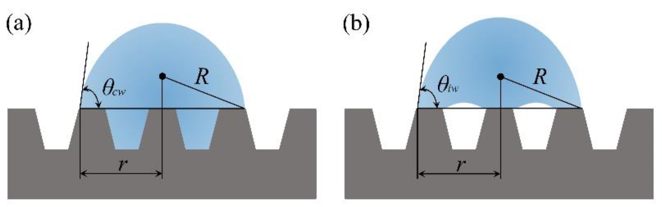
2.2. Establishment of Complete Wetting Prediction Model

According to Figure 3a and the parameters in Figure 2, the contact areas of solid–liquid and liquid–gas phases under complete wetting prediction model can be expressed in follows:
A sl = π r 2 2 π h r 2 ( sin   U   1 ) ( a + b ) cos   U
A gl = 0 θ c w 2 π r R d θ = 2 π r 2 1 + cos   θ w
Since the contact area of solid–gas phases cannot be expressed directly, the surface area of the trapezoidal groove structure As is introduced to represent the interface area:
A sg = A s A sl
By substituting the above contact areas into Equation (4), there is:
cos θ Y = γ sg   γ sl γ gl = d A gl d A sl = ( a + b ) cos   U ( a + b ) cos   U 2 h ( sin   U   1 ) × cos   θ c w
Then, the relationship between the intrinsic contact angle θ and the complete wetting contact angle θcw can be expressed by Equation (11):
cos   θ c w = [ 1     2 h ( sin   U   1 ) ( a + b ) cos   U ] cos   θ Y
According to Equation (11), when the depth of the trapezoidal groove structure is constant, a three-dimensional diagram of the width, spacing, and contact angle of the convex plate under complete wetting prediction model is shown in Figure 4.
It can be seen from Figure 4 that when width of trapezoidal groove structure is larger or the top edge length of spacing of the trapezoidal groove structure is larger, the predicted contact angle will increase gradually. In particular, the contact angle can reach the maximum value when the width and top edge length of spacing are larger at the same time.

2.3. Establishment of Incomplete Wetting Prediction Model

When the droplet on the trapezoidal groove structure is simulated by an incomplete wetting model as shown in Figure 3b, the contact areas of those three phases are different.
Based on the parameters in Figure 2, the contact areas of the solid–liquid phase under incomplete wetting prediction model can be obtained:
A sl = S = a π r 2 a + b
In the incomplete wetting prediction model, the contact area between the gas phase and liquid phase is quite different from that under the complete wetting prediction model. At this point, a partial enlarged view of the trapezoidal groove structure is shown in the Figure 5.
When the droplet is in contact with the microstructure, the surface curvature of the droplet will make the actual contact line between the gas and the liquid become curved. The angle θY between the two phases is the intrinsic contact angle of the material. In this paper, the intrinsic contact angle of the PMMA measured by the DataPhysics OCA optical contact angle measuring instrument (Dataphysics, Stuttgart, Germany) is 64°, there is:
m b
Then, the contact area of liquid–gas phases can be obtained:
A gl = 0 θ i w 2 π r R d θ + ( π r 2 A sl ) = 2 π r 2 1 + cos   θ i w + π r 2 a π r 2 a + b
Moreover, the contact area of solid–gas phases under incomplete wetting prediction model can be expressed in the same way as that under complete wetting prediction model.
A sg = A s A sl
Combining Equations (4) and (5), there is:
cos   θ i w = a a + b ( cos   θ Y + 1 )     1
Then, the three-dimension curve of the width, spacing, and contact angle of the convex plate under incomplete wetting prediction model can be obtained, as shown in Figure 6.
As shown in Figure 6, the contact angle will be the largest when the width of trapezoidal groove structure is smaller and the top edge length of spacing are larger at the same time. For single factor variables, it can be seen that the smaller the width of trapezoidal groove structure, the larger the prediction contact angle. It is worth noting that the prediction contact angle will take a larger value when the top edge length of spacing increases gradually.

3. Experiment and Verification

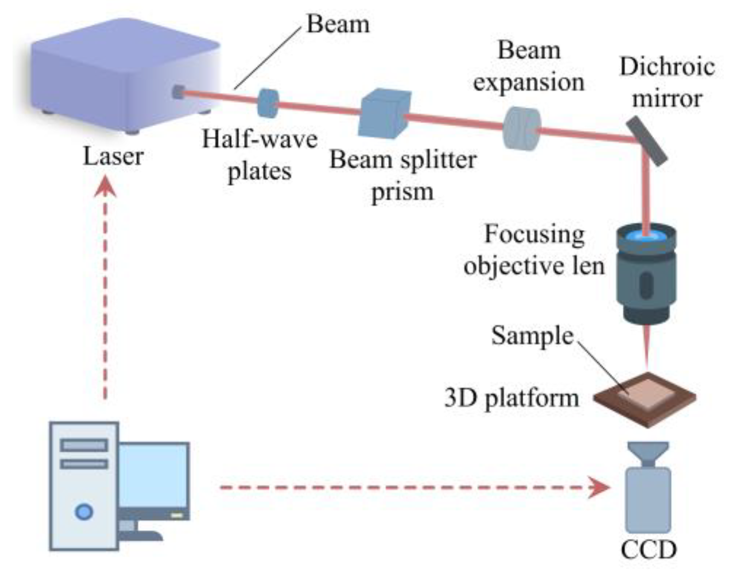
3.1. Experimental Equipment and Processing Parameters

In this work, experiment was conducted using Origami-10XP femtosecond laser. The femtosecond laser processing system is shown in Figure 7.
In this processing system, the output power of laser is 4 W, pulse width is 400 fs, and wavelength is 1030 nm. The incident laser is linearly polarized. The trapezoidal groove structure shown in the Figure 2 was processed under the above conditions. The dichroic mirror in this system is to reflect laser and allow natural light to pass through. The 3D platform (SPiiPlusEC, ACS, Migdal Ha-Emekity, Israel) is controlled by computer to achieve precise control for the processing structure. The stroke of the x-axis and y-axis is 50 mm, and the repetition accuracy is ±0.5 μm. The vertical movement speed of the platform is 50 μm/s. The purpose of CCD is to realize the online monitoring of the microstructure of PMMA during the construction.
Based on the structure of Figure 2, the trapezoidal groove structural parameters were selected by the predicted contact angle, as shown in Table 1. There were two types of PMMA samples in the experiment. The top edge length of spacing of the samples which were numbered 1 was 100 μm, and the top edge length of spacing of the samples which were numbered 2 was 200 μm.
The polymethyl methacrylate (PMMA) with size of 600 mm × 400 mm and thickness of 3000 μm was selected as experimental material. The PMMA was cleaned with absolute ethanol and deionized water to remove impurities on the surface and ensure the reliability of experimental measurement before constructing structures. In this paper, the output power of laser beam is 1.5 W, and the speed of processing was set to 10 mm/s in the experiment.

3.2. Observation of Processed Samples

After processing, all the samples were placed in an ultrasonic cleaner (JP-010T, Skymen, Shenzhen, China) containing alcohol for 5 min to remove the impurities on the surface. Then, the deionized water was used to remove the residual alcohol solution. At last, the metallographic tapes were stuck on the surface of PMMA to ensure the accuracy of subsequent measured data.
In this paper, the super-high-magnification lens zoom 3D microscope (VHX-5000, Keyence, Osaka, Japan) was used to observe the morphology of PMMA. Figure 8 shows the partial morphology of microstructure of trapezoidal groove structure on PMMA with a multiple of 500 times.
The hydrophobicity of the surface was measured by the optical contact angle measuring instrument (OCA, DataPhysics, Filderstadt, Germany). The quantity of 2 μL of deionized water was used for the measurement. The injection needle is controlled by software to ensure the accuracy of the injected droplets, and the measurement accuracy is ±0.1°.
Considering the array characteristics of the trapezoidal groove structure on PMMA, the measurements were performed parallel to the direction of the convex. The contact angle of each specimen was measured five times to reduce the randomness of the data.

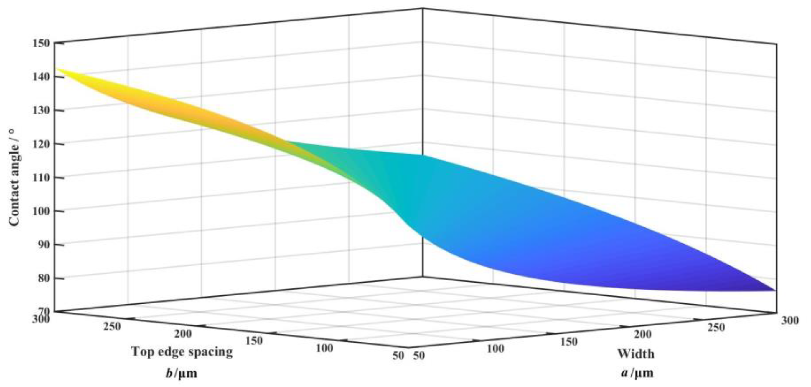
4. Results and Discussion

Table 2 shows the experimentally measured value and predicted value of contact angle.
Figure 9 is the curve of contact angle as a function of convex width of trapezoidal groove structure.
According to Figure 9, it is clear that the experimentally measured contact angle of number 1 samples and number 2 samples were very close to their predicted contact angle under incomplete wetting model. The hydrophobicity of PMMA can be achieved by preparing micro/nano structure on the surface of PMMA within the effective size parameters. The measured contact angle was very close to the contact angle predicted by the incomplete wetting model within the error range. As a result, the incomplete wetting model is more reasonable and accurate. Figure 10 shows the schematic diagram of measurement of contact angles on PMMA, which also validates the core idea of this paper that the preparation of micron-scale structure on the surface of PMMA can realize the transition from hydrophilicity to hydrophobicity.
The predicted and experimental contact angle curves show that the smaller the width of convex of trapezoidal groove structure, the larger the contact angle. Thus, the hydrophobicity of surface of PMMA can be enhanced by reducing the convex width.
It could be seen that the predicted and experimental contact angles of the samples which were numbered 2 were always significantly larger than those of the samples which were numbered 1. It is clear that not only the value of convex width will influence the hydrophobicity of PMMA, but also the top edge length of spacing plays a synergistic role. Based on the 3D curve of contact angle and structural parameter of incomplete wetting prediction model in Figure 6, the influence of the convex width and the top edge length of spacing of the trapezoidal groove structure on the contact angle can be obtained. Actually, the smaller the ratio of the convex width to the top edge length of spacing, the larger the contact angle on the surface of PMMA and the better the hydrophobicity of PMMA surface.
The experimentally measured contact angle was always larger than the predicted contact angle, as shown in Figure 9. The average difference between the experimental value and the predicted value of the contact angle is 4.13. Figure 11 shows the 3D topography and cross section of samples measured by the super-high-magnification lens zoom 3D microscope.
It can be seen from Figure 11, that there are some micro-convex structures on the edge of the trapezoidal groove structures in all samples, which make the top edge length spacing of the trapezoidal groove larger than the originally designed spacing slightly. It can be seen from Figure 6 that the larger the top edge spacing of the trapezoidal groove structure, the greater the contact angle, and the better the hydrophobicity.
Actually, the convex structures on the edge of the trapezoidal groove structure are generated by the interaction of laser and PMMA. When the femtosecond laser interacts with the polymer materials, there will be a critical repetition rate, which makes the irradiation of materials by femtosecond laser divided into non-thermal and thermal regime. The critical frequency fcr can be calculated according to Equation (17) [32]:
f c r = D t h d 2
where d represents the laser beam diameter, and the beam diameter in this research is 2.914 μm. Dth is the thermal diffusivity, which can be obtained by Equation (18):
D t h = K ρ c
where K, ρ and c are the thermal conductivity, the density, and the specific heat of PMMA, respectively. At room temperature, there is: K = 0.36 W·(mK)−1, c = 1.465 J·(gK)−1, ρ = 1.18 g·cm−3. Based on the above calculation, the critical frequency is 24.5 kHz. However, the pulse repetition rate of femtosecond laser in this research is 100 kHz, which is much greater than the critical frequency. As a result, the pulse repetition rate is large enough to ensure the release of energy generated by thermal accumulation, forming a thermal regime [33]. However, it can be seen that the grooves are smooth, which indicated that the thermal degradation dominated in the laser ablation [34]. Therefore, there is no significant thermal effect near the trapezoidal groove structure of PMMA. The thermal accumulation mainly leads to the thermal degradation of PMMA, and the escape of degradation products makes the processing area almost free of thermal influence.
The focus position variation plays a significant role in this process [35,36]. When the focus of laser irradiates the bottom of the trapezoidal groove, the energy absorbed by the upper material of the PMMA is less than the absorption threshold of the material of PMMA, which causes the lower part of the material to decompose and generate internal stress. However, the focus position will gradually move upward during the machining of the trapezoidal groove structure. At that time, the deformation caused by the internal stress will also gradually move up, and a micro-convex structure as shown in Figure 12 will be generated on the upper edge of the trapezoidal groove structure eventually.
Figure 13 shows the microstructure topography and cross section of trapezoidal groove of samples. It is clear that there are some raised microstructures in all three sample at A1, A2, B1, B2, C1 and C2 due to the movement of the focus position, which are in line with the structure in Figure 12c.
It can be seen from Figure 11 that the spacing of the processed trapezoidal groove will be gradually increased from the bottom of the groove to the top of the groove. The top edge spacing of the trapezoidal groove is the largest of the groove. This is consistent with the trend that the smaller the ratio of the convex width to the top edge length of spacing, the larger the contact angle, which well explains why the experimentally measured value is always greater than the predicted value.

5. Conclusions

Two kinds of the contact angle prediction models (i.e., complete wetting prediction model and incomplete wetting prediction model) were established based on the structural parameters in this paper. The microstructure studied in this paper is designed by combining the interaction characteristics of laser and PMMA. Considering the Gaussian distribution of the laser beam, the trapezoidal groove structure was designed and studied. Based on numerical analysis of the contact angle prediction model and the subsequent experimental research, it can be found that the incomplete wetting prediction model constructed in this paper is more in line with the actual situation as compared with the complete wetting prediction model.
According to the analysis of the two groups of experimental data, it can be found that the convex width of the trapezoidal groove and the top edge length of spacing of trapezoidal groove structure both have an impact on the contact angle. The smaller the ratio of the convex width to the top edge length of spacing, the larger the contact angle and the better the hydrophobicity of PMMA. Overall, the contact angle prediction model constructed can predict the contact angle of PMMA correctly and accurately, which is instructive for the construction of hydrophobic structures.

Author Contributions

Writing—original draft preparation, B.W.; software, Z.W.; data curation, J.S.; writing—review and editing, B.W.; project administration, Y.Z. All authors have read and agreed to the published version of the manuscript.

Funding

This research was funded by National Natural Science Foundation of China, Joint fund project of Liaoning Province, No. U1608259; National Natural Science Foundation of China, No. 51775117; Science and technology program of Guangdong Province, No. 2017B090911013; National key research and development program, No. 2017YFB1103600 and Project of scientific research innovation plan for Postgraduates in Jiangsu Province, No. CXZZ13_0657.

Conflicts of Interest

The authors declare no conflict of interest.

References

  1. Yan, Y.Y.; Gao, N.; Barthlott, W. Mimicking natural superhydrophobic surfaces and grasping the wetting process: A review on recent progress in preparing superhydrophobic surfaces. Adv. Colloid Interface Sci. 2011, 169, 80–105. [Google Scholar] [CrossRef]
  2. Cui, C.; Duan, X.; Collier, B.; Poduska, K.M. Fabrication and wettability analysis of hydrophobic stainless steel surfaces with microscale structures from nanosecond laser machining. J. Micro Nano-Manuf. 2018, 6, 031006. [Google Scholar] [CrossRef]
  3. Cao, Z.; Ding, W.; Ma, Z.; Wang, B.; Wang, Z. Research on the hydrophobicity of square column structures on monocrystalline silicon fabricated using micro-machining. Micromachines 2019, 10, 763. [Google Scholar] [CrossRef] [Green Version]
  4. Hu, L.; Zhang, L.; Wang, D.; Lin, X.; Chen, Y. Fabrication of biomimetic superhydrophobic surface based on nanosecond laser-treated titanium alloy surface and organic polysilazane composite coating. Colloids Surf. A 2018, 555, 515–524. [Google Scholar] [CrossRef]
  5. Ding, W.; Cao, Z.; Wang, B.; Xu, S.; Wang, Z. Research on hydrophobic properties of grating structure on monocrystalline silicon fabricated using micromachining. Adv. Mater. Sci. Eng. 2019, 2019, 1–10. [Google Scholar] [CrossRef] [Green Version]
  6. Sun, T.; Feng, L.; Gao, X.; Jiang, L. Bioinspired surfaces with special wettability. Acc. Chem. Res. 2005, 38, 644–652. [Google Scholar] [CrossRef]
  7. Razavi Seyed Mohammad, R.; Oh, J.; Sett, S.; Feng, L.; Yan, X.; Hoque, M.J.; Liu, A.; Haasch, R.T.; Masoomi, M.; Bagheri, R.; et al. Superhydrophobic surfaces made from naturally derived hydrophobic materials. ACS Sustain. Chem. Eng. 2017, 5, 11362–11370. [Google Scholar] [CrossRef]
  8. Song, H.; Liu, Z.; Shi, Z.; Cai, Y. Model of contact angle of hydrophobic surface based on minimum Gibbs free energy. J. Shandong Univ. (Eng. Sci.) 2015, 45, 56–61. [Google Scholar]
  9. Wu, F.; Shi, G.; Xu, H.; Liu, L.; Wang, Y.; Qi, D.; Lu, N. Fabrication of antireflective compound eyes by imprinting. ACS Appl. Mater. Interfaces 2013, 5, 12799–12803. [Google Scholar] [CrossRef]
  10. Wang, J.; Liu, F.; Chen, H.; Chen, D. Superhydrophobic behavior achieved from hydrophilic surfaces. Appl. Phys. Lett. 2009, 95, 084104. [Google Scholar] [CrossRef]
  11. Chen, Z.; Hao, L.; Chen, A.; Song, Q.; Chen, C. A rapid one-step process for fabrication of superhydrophobic surface by electrodeposition method. Electrochim. Acta. 2012, 59, 168–171. [Google Scholar] [CrossRef]
  12. Hu, Y.; Lao, Z.; Cumming, B.P.; Wu, D.; Li, J.; Liang, H.; Chu, J.; Huang, W.; Gu, M. Laser printing hierarchical structures with the aid of controlled capillary-driven self-assembly. Proc. Natl. Acad. Sci. USA 2015, 112, 6876–6881. [Google Scholar] [CrossRef] [Green Version]
  13. Chichkov, B.N.; Momma, C.; Nolte, S.; Von Alvensleben, F.; Tünnermann, A. Femtosecond, picosecond and nanosecond laser ablation of solids. Appl. Phys. A 1996, 63, 109–115. [Google Scholar] [CrossRef]
  14. Zorba, V.; Stratakis, E.; Barberoglou, M.; Spanakis, E.; Tzanetakis, P.; Fotakis, C. Tailoring the wetting response of silicon surfaces via fs laser structuring. Appl. Phys. A 2008, 93, 819–825. [Google Scholar] [CrossRef]
  15. Zhu, D.; Hu, J. Experimental study on picosecond pulsed laser machining of carbon fiber reinforced plastics. Aeronaut. Manuf. Technol. 2017, 20, 54–59. [Google Scholar]
  16. Zhang, H.Z.; Wang, H.Y.; Liu, F.F.; Wang, L. Investigation on femtosecond laser ablative processing of SiCp/AA2024 composites. J. Manuf. Process. 2020, 49, 227–233. [Google Scholar] [CrossRef]
  17. Riveiro, A.; Abalde, T.; Pou, P.; Soto, R.; del Val, J.; Comesaña, R.; Badaoui, A.; Boutinguiza, M.; Pou, J. Influence of laser texturing on the wettability of PTFE. Appl. Surf. Sci. 2020, 515, 145984. [Google Scholar] [CrossRef]
  18. Qin, Z.; Ai, J.; Du, Q.; Liu, J.; Zeng, X. Superhydrophobic polytetrafluoroethylene surfaces with accurately and continuously tunable water adhesion fabricated by picosecond laser direct ablation. Mater. Des. 2019, 173, 107782. [Google Scholar] [CrossRef]
  19. Farshchian, B.; Gatabi, J.R.; Bernick, S.M.; Lee, G.H.; Droopad, R.; Kim, N. Scaling and mechanism of droplet array formation on a laser-ablated superhydrophobic grid. Colloids Surf. A 2018, 547, 49–55. [Google Scholar] [CrossRef]
  20. Waugh, D.; Lawrence, J. On the use of CO2 laser induced surface patterns to modify the wettability of Poly (methyl methacrylate) (PMMA). Opt. Lasers Eng. 2010, 48, 707–715. [Google Scholar] [CrossRef] [Green Version]
  21. Zhang, C.; Cao, M.; Ma, H.; Yu, C.; Li, K.; Yu, C.; Jiang, L. Morphology-control strategy of the superhydrophobic poly (methyl methacrylate) surface for efficient bubble adhesion and wastewater remediation. Adv. Funct. Mater. 2017, 27, 1702020. [Google Scholar] [CrossRef]
  22. Li, J.; Wang, W.; Mei, X.; Pan, A.; Sun, X.; Liu, B.; Cui, J. Artificial compound eyes prepared by a combination of air-assisted deformation, modified laser swelling, and controlled crystal growth. ACS Nano 2019, 13, 114–124. [Google Scholar] [CrossRef]
  23. Wenzel, R.N. Resistance of solid surfaces to wetting by water. Ind. Eng. Chem. 1936, 28, 988–994. [Google Scholar] [CrossRef]
  24. Cassie, A.B.; Baxter, S. Wettability of porous surfaces. Trans. Faraday Soc. 1944, 40, 546–551. [Google Scholar] [CrossRef]
  25. Bittoun, E.; Marmur, A. Optimizing super-hydrophobic surfaces: Criteria for comparison of surface topographies. J. Adhes. Sci. Technol. 2009, 23, 401–411. [Google Scholar] [CrossRef]
  26. Zhenyu, S.; Zhanqiang, L.; Hao, S.; Xianzhi, Z. Prediction of contact angle for hydrophobic surface fabricated with micro-machining based on minimum Gibbs free energy. Appl. Surf. Sci. 2016, 364, 597–603. [Google Scholar] [CrossRef] [Green Version]
  27. Drelich, J.W.; Boinovich, L.; Chibowski, E.; Della Volpe, C.; Hołysz, L.; Marmur, A.; Siboni, S. Contact angles: History of over 200 years of open questions. Surf. Innov. 2020, 8, 3–27. [Google Scholar] [CrossRef] [Green Version]
  28. Shirtcliffe, N.J.; McHale, G.; Atherton, S.; Newton, M.I. An introduction to superhydrophobicity. Adv. Colloid Interface Sci. 2010, 161, 124–138. [Google Scholar] [CrossRef] [Green Version]
  29. Kwon, M.; Shin, H.; Chu, C. Fabrication of a super-hydrophobic surface on metal using laser ablation and electrodeposition. Appl. Surf. Sci. 2014, 288, 222–228. [Google Scholar] [CrossRef]
  30. Peng, D.; Li, P.; Hou, R. Effect of aperture in femtosecond laser optical path on machining of microholes. Laser Infrared. 2019, 49, 1201–1205. [Google Scholar]
  31. Cai, Y.; He, S. Propagation of hollow Gaussian beams through apertured paraxial optical systems. J. Opt. Soc. Am. A Opt. Image Sci. Vis. 2006, 23, 1410–1418. [Google Scholar] [CrossRef]
  32. Sola, D.; Cases, R. High-repetition-rate femtosecond laser processing of acrylic intra-ocular lenses. Polymers 2020, 12, 242. [Google Scholar] [CrossRef] [Green Version]
  33. Misawa, H.; Juodkazis, S. 3D Laser Microfabrication: Principles and Applications; Wiley-VCH: Weinheim, Germany, 2006. [Google Scholar]
  34. Luo, Y.; Jia, W.; Song, Y.; Liu, B.; Hu, M.; Chai, L.; Wang, C. High-repetition-rate femtosecond laser micromachining of poly(methyl methacrylate). Chin. Opt. Lett. 2015, 13, 070003. [Google Scholar]
  35. Li, J.; Wang, W.; Mei, X.; Sun, X.; Pan, A. The formation of convex microstructures by laser irradiation of dual-layer polymethylmethacrylate (PMMA). Opt. Laser Technol. 2018, 106, 461–468. [Google Scholar] [CrossRef]
  36. Meunier, T.; Villafranca, A.B.; Bhardwaj, R.; Weck, A. Mechanism for spherical dome and microvoid formation in polycarbonate using nanojoule femtosecond laser pulses. Opt. Lett. 2012, 37, 3168–3170. [Google Scholar] [CrossRef]
Figure 1. Schematic diagram of laser beam.
Coatings 10 00386 g001
Figure 2. Trapezoidal groove structure.
Coatings 10 00386 g002
Figure 3. Wetting model on trapezoidal groove structure: (a) complete wetting model and (b) incomplete wetting model.
Coatings 10 00386 g003
Figure 4. Three-dimension curve of contact angle and structural parameter under complete wetting prediction model.
Coatings 10 00386 g004
Figure 5. Schematic diagram of gas-liquid interface contact line.
Coatings 10 00386 g005
Figure 6. Three-dimension curve of contact angle and structural parameter under incomplete wetting prediction model.
Coatings 10 00386 g006
Figure 7. Femtosecond laser processing system.
Coatings 10 00386 g007
Figure 8. Schematic diagram of trapezoidal groove structure (×20).
Coatings 10 00386 g008
Figure 9. The predicted and experimental contact angle curves.
Coatings 10 00386 g009
Figure 10. Contact angles of polymethyl methacrylate (PMMA): (a) un-machined PMMA and (b) sample 1-3.
Coatings 10 00386 g010
Figure 11. Three-dimensional (3D) topography and cross section of trapezoidal groove structures (×200): (a) sample 1-3, (b) sample 1-4 and (c) sample 1-6.
Coatings 10 00386 g011
Figure 12. The diagram of the evolution mechanism of trapezoidal groove structure: (a) processing of bottom of trapezoidal groove, (b) upward movement of focus and (c) processing of top of trapezoidal groove.
Coatings 10 00386 g012
Figure 13. Microstructure topography and cross section of trapezoidal groove structures (×1000): (a) sample 1-3, (b) sample 1-4 and (c) sample 1-6.
Coatings 10 00386 g013
Table 1. Parameters of trapezoidal groove structure.
Sample NumberDepth h/μmTop Edge Length of Spacing b/μmWidth of Convex a/μm
1-110010050
1-2100100
1-3100150
1-4100200
1-5100250
1-6100300
2-110020050
2-1200100
2-2200150
2-3200200
2-5200250
2-6200300
Table 2. The predicted and experimental values of contact angle.
Sample NumberExperimentComplete Wetting Prediction ModelIncomplete Wetting Prediction Model
1-1125.30 ± 2.844.96121.4
1-2111.02 ± 3.2950.19106.3
1-3100.86 ± 2.753.1497.87
1-497.35 ± 3.955.0492.35
1-589.35 ± 1.356.3888.43
1-687.08 ± 2.6757.3685.48
2-1138.09 ± 4.6353.14135.4
2-2126.34 ± 3.6255.04121.4
2-3121.07 ± 3.856.38112.6
2-4109.75 ± 2.9157.36106.3
2-5108.40 ± 4.8658.12101.6
2-6101.57 ± 3.2958.7397.87

