Article

Evolution of Microstructure at the Surface of 40CrNiMo7 Steel Treated by High-Current Pulsed Electron Beam

1
School of Fundamental Education, Dalian Neusoft University of Information, Dalian 116023, China
2
Key Laboratory of Intelligent Control and Optimization for Industrial Equipment of Ministry of Education, Dalian University of Technology, Dalian 116024, China
3
Key Laboratory of Materials Modification by Laser, Ion and Electron Beams & School of Material Science and Engineering, Dalian University of Technology, Dalian 116024, China
*
Author to whom correspondence should be addressed.
Coatings 2020, 10(4), 311; https://doi.org/10.3390/coatings10040311
Submission received: 26 February 2020 / Revised: 17 March 2020 / Accepted: 19 March 2020 / Published: 25 March 2020

Abstract

:
High current pulsed electron beam (HCPEB) has recently been developed as an effective technique of material surface modification. In this research, a self-developed HCPEB equipment (HOPE-I) was adopted to perform surface modification on quenched and tempered 40CrNiMo7 steel. A composite nanometer structure was formed on the modified surface layer, and the martensite transformation and the dissolution and fracture of cementite can be observed. After initial irradiation, the high cooling rate caused the formation of nanocrystalline on the surface. With continuous irradiation treatments, the cooling rate gradually reduced, while the carbon kept dissolving and ended with surface composition homogenization. Both competitive factors result in the evolution rule of nanometer dimensions of surface structure. After HCPEB treatment, the average size of austenite phase on the modified surface decreased from micron-sized to nanoscale. The corrosion rate decreased from 0.12 mm/a to 0.02 mm/a, showing remarkable improvement of corrosion resistance. The main factors of the improvements of corrosion resistance property are the flat, dense structured and preferred crystal orientation on the modification layer of the treated material surface.

1. Introduction

High-strength structural steels have been widely used in the manufacture of core mechanical components such as heavy loading shafts, large-section shafts, gas turbine cranks and gears, engines and various pump systems. As a typical low-alloy structural steel, 40CrNiMo7 steel is a kind of chrome-nickel-molybdenum steel, which has good performance and is widely used to withstand the impact load of parts and large section, high load shaft class. Though these types of structural steel can well meet the requirements of heavy load and frequent impact. It also suffers from inherent shortcomings, such as relatively low hardness, soft dot. Especially when the structural steel bears a large load for a long time. Thus, local spalling and excessive wear on the bearing surface will damage the integrity of the structure. If no effective measures are taken, the expected service life will be significantly shortened with the accumulation of friction effect, even resulting in the failure of the whole machine and even industrial accidents [1,2,3,4]. Up to now, there have been few reports on surface treatment of high-strength structural steel parts with improved surface performance. Therefore, Special treatment of 40CrNiMo7 steel is urgently needed to improve its practicability.
In recent years, high-current pulsed electron beam (HCPEB) has been developed rapidly and proved to be an effective material surface-modification technology. Hao et al. [5,6,7,8] designed a new type of HCPEB source by using the advantages of large diameter, high density plasma and long distance channel. As the extremely high energy density (10 8 –10 9 W/cm 2 ) shifts to the surface of materials in a very thin layer (no more than tens of micrometers) within a few microseconds, causing extremely rapid melting or even evaporation and resulting in surface tissue imbalance and accompanied by changes in physicochemical properties [9,10]. Meanwhile, self-quenching ( 10 8 10 9 Ks - 1 ) and thermal stress impact processes occur quite intensively in the near-surface layers [11,12,13,14]. Meanwhile, self-quenching ( 10 8 10 9 Ks - 1 ) and thermal stress impact processes occur quite intensively in the near surface layers. Meanwhile, there have been very interesting results with mechanical methods such as ultrasonic-vibration-assisted ball burnishing on Ti-6Al-4 V surfaces [15]. Compared with other surface engineering methods such as surface carbonization or nitriding, film and coating deposition, and even laser and ion beam technology, modern HCPEB equipment with good handling adaptability has significant advantages in terms of efficiency, reliability, and low cost [16,17]. In this paper, the HCPEB surface treatment of 40CrNiMo7 steel was carried out to study the microstructure evolution mechanism and the associated corrosion properties.

2. Materials and Methods

The quenched and tempered 40CrNiMo7 steel is supplied by Shenyang Blower Group Co., Ltd. The experimental samples were wire-cut in the tempered state of 40CrNiMo7 ingot, and its chemical composition is shown in Table 1. The sample size was 10 mm × 10 mm × 8 mm and 15 mm × 15 mm × 8 mm. Firstly, the wire-cut samples were cleaned and decontaminated with acetone. After grinding the metallographic sandpaper in 200 # , 400 # , 600 # , 800 # , 1000 # , 1200 # , 1500 # , 2000 # step by step, the diamond abrasive pasted with a particle size of 1.5w was used for precise polishing. The samples were cleaned with an alcohol solution and then dried for use. The surface modification of 40CrNiMo7 ingot was carried out with the independently developed hope-I HCPEB device. The process parameters of the electron beam equipment used in the experiment are as follows: the working environment vacuum is 8 × 10 - 3 Pa, the acceleration voltage is 27 kV, the sample-target distance is 7 cm, the pulse duration is 2.5 s, the energy density is 3 J/cm 2 , and the pulse frequency are 1, 3, 8, 15, 25 and 50 times, respectively.
The changes of surface microstructure and microstructure before and after modification were observed with Olympus GX51 optical microscope (OM), JEOL jsm-7100f and jsm-6360lv scanning electron microscope (SEM) and jem-2100 transmission electron microscope (TEM). The samples were prepared by the unilateral thinning method. Firstly, the sample was mechanically thinned to 80 nm on one side and punched ( ϕ 3 mm); Then the sample was unilaterally thinned to ≤50 m on one side by using the Gatan Disc Grinder623 manual grinding disc; The sample was further thinned to ∼25 m by using the Model 656 Dimple Depth ultra-precision dimpling grinder, and the sample was ultimately thinned to center perforation by using the Danish Struer-Tenupol-5 dual-jet electrolytic thinning apparatus. The thinning solution was 9 % perchloric acid, the experimental voltage was 26v, and the temperature was −30 C (in liquid nitrogen). The surface roughness of the sample was measured by TR110 surface profilometer. The surface phase structure of the modified sample was analyzed by the Empyrean X-ray diffraction (XRD). Cu target K α radiation was adopted, characteristic wavelength λ = 1 . 5406 nm, step length 0 . 025 , acceleration voltage 40 kV, and scanning range ( 2 θ ) of 20∼ 100 were used. The CS350 electrochemical workstation was used for corrosion resistance testing. The system was composed of three electrodes, including the working electrode sample, reference electrode saturated calomel (SCE), and auxiliary electrode Pt. The corrosive medium was 3 . 5 % NaCl solution, the effective test area was 10 mm × 10 mm, and the experimental temperature was room temperature.

3. Results and Discussion

3.1. Surface and Cross-Sectional Morphology

After quenching and tempering heat treatment, the original microstructure of 40CrNiMo7 steel becomes tempered sorbite, and the composite microstructure of carbide pellet is generated in the matrix ferrite [7]. It can be seen from the figure that the high-temperature tempering martensite strips were generated, among which dispersedly distributed with cementite, carbide precipitate and a small amount of strip ferrite phase structure of different sizes. The original grain size is about 10 microns, as shown in Figure 1a.
After once pulse HCPEB treatment, as shown in Figure 1b, a large number of molten pits were formed on the surface of the sample, and the thermophysical difference between the original ferrite, cementite and carbide results in the modified surface melt and form molten droplets at the phase boundary firstly, which is consistent with the literature [18,19], the eruption source of the molten pit is closely related to the phase structure defects of HCPEB treated surface and the difference in thermophysical properties of the surface phase structure. In addition, it is commonly recognized that the electron beam irradiation penetrating heating mode causes the melting of treated samples to start in the subsurface layer. It can be observed from Figure 1c that the morphology of splash of molten droplets is shown in the enlarged metallographic diagram of molten pits. The reason is that when the energy density increases to a certain value, the molten metal tends to gasify, along with the spill of molten metal droplets, and the morphology of transient plume distribution can be generated.
The surface roughness of samples before and after HCPEB treatment was measured by surface profilometer. The results showed that the average surface roughness (Ra) of the original polished samples was 0.13 μ m. After one pulse treatment, the roughness of the modified sample surface increase to 0.54 μ m. This is because a large number of craters formed on the sample surface after the first HCPEB treatment, hence the roughness of the modified surface increased correspondingly. The surface roughness was 0.48 μ m and 0.36 μ m after 3 and 8 pulses HCPEB treatments, respectively. After 15 pulses treatment, the modified surface became smoother with the roughness less than 0.2 μ m. With the increase of pulse numbers, the treated sample surface underwent repeated remelting and the crater density gradually decreased, then the modified surface became smoother and denser, and the microstructure was refined and uniform, in this way, the modified surface roughness gradually decreased as shown in Figure 2. Wang et al. [20] studied the influence of surface roughness on micro-dynamic friction and wear properties. They found that the wear rate decreases monotonically with the decrease of surface roughness in dry friction condition, and the worn surface with low roughness has a few furrows and slight plastic deformation.
The high magnification SEM morphology observation results of the modified surface after HCPEB treatments are shown in Figure 3. After the initial pulse treatment, the modified surface of the sample showed obvious melting traces, and many embedded acicular structures were observed covering the modified surface (Figure 3a). When the cooling rate is sufficient to avoid the diffusion phase transition, martensitic phase transition can occur in all metals and alloys at high temperature, while the appearance of embedded acicular structure on the modified surface indicates that martensitic phase transition may occur on the modified surface after HCPEB treatment, with the formation of martensitic phase transition. After 15 pulse treatments, the modified surface gradually flattens out, and the embedded needle structure becomes smaller in size and more evenly distributed (Figure 3c). After 50 pulse treatments, it can be seen from Figure 3d that the modified surface is more smooth and even, and the size of the embedded needle structure is more refined. The results showed that with the increase of HCPEB treatment times, the formation of embedded acicular structures related to martensitic transformation in the modified subsurface layer was gradually inhibited. In addition, the SEM morphology observation results of the modified surface at high power are shown in Figure 3b,d,f. The embedded needle-like structure of the modified surface is shown as a ridge of uplift and is covered by a layer of fine nanoscale grains. The following XRD and TEM analysis results show that these nanoscale grains can be identified as a complex phase structure, the majority of which is a nano-austenitic phase. Thus, the crystallization process occurred on the modified surface during rapid heating and rapid cooling after HCPEB treatment, resulting in the formation of nanoscale grains.
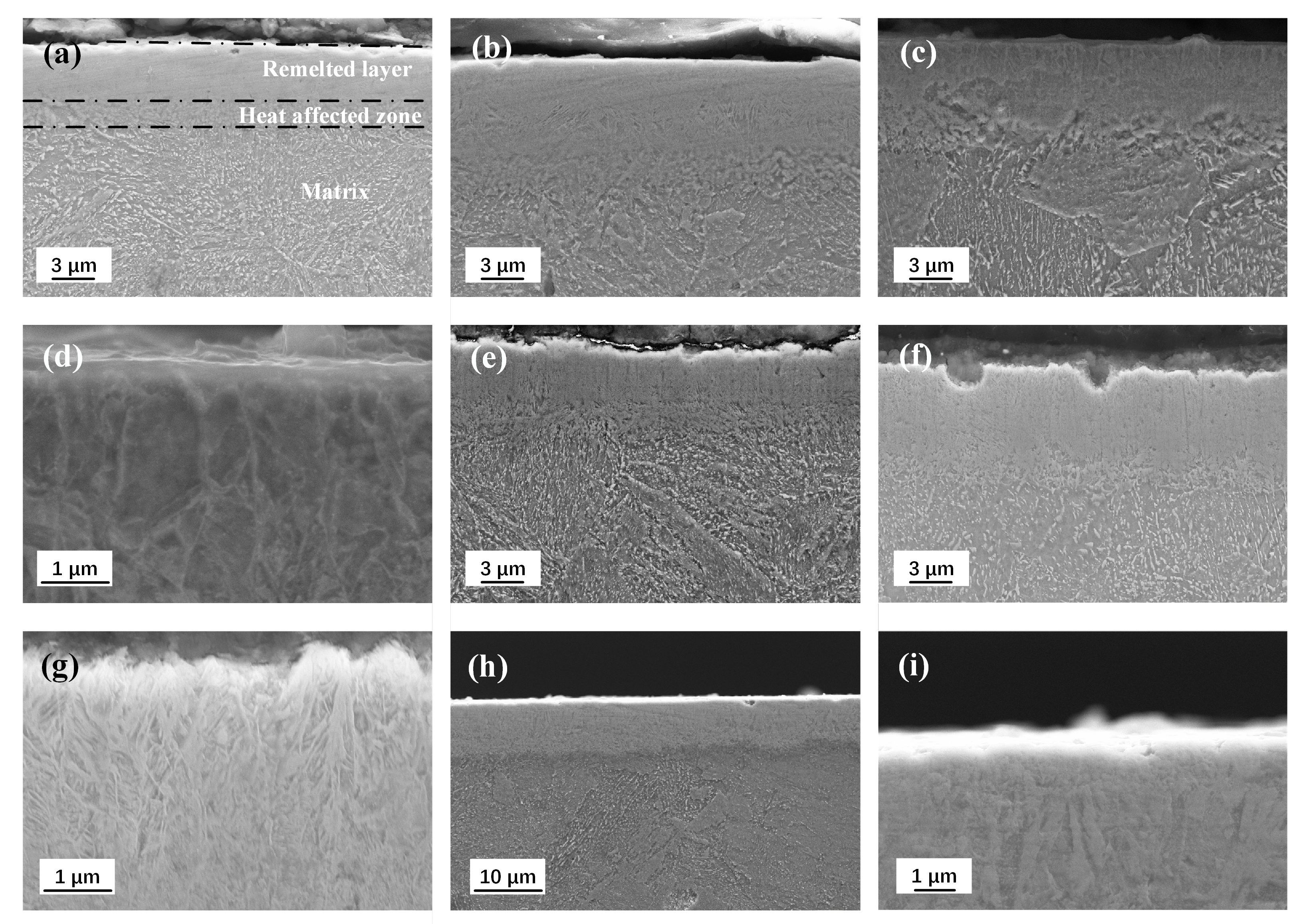
Figure 4 shows the cross-sectional SEM morphologies of the samples after HCPEB treatment with different pulse numbers. The modified surface shows obvious stratification, remelting layer, heat-affected zone and matrix can be seen from top to bottom. After one and three pulse treatments, the remelting layer of the modified surface shows uniform contrast, and the microstructure in the heat-affected zone is significantly more refined than that in the matrix (Figure 4a,b). After 8 pulses HCPEB treatments, columnar crystals growing parallel to the incident direction of the electron beam in the remelting layer were observed in Figure 4c,d, and the texture in the heat-affected zone was evenly refined. The cooling rate can reach up to 10 8 10 9 ks - 1 and the crystallization rate can reach up to 2∼5 m/s. The melt generated on the irradiation surface grew rapidly into the columnar crystal in the opposite direction from the heat dissipation direction.
After 15 pulse treatments, the typical layered structure of the modified surface can be observed, as shown in Figure 4e. After 25 pulses HCPEB treatments, the dendritic structure can be clearly seen in high magnification SEM morphology (Figure 4f,g). Such highly branched crystal with primary dendrites parallel to the electron beam heat flow direction are called columnar dendrites. When the liquid phase of the columnar crystals formed in the modified remelting layer was extremely subcooled before solidification, the latent heat released during solidification increased the temperature of the solid-liquid phase interface, and then the interface will bulge and form columnar crystals. A similar process could occur on the sides of the column crystals, which grows in a dendritic form and form dendrites. Temperature gradient and growth rate are two basic solidification parameters that determine the morphology and size of the microstructure. With the increase of pulse number, alloy and carbon elements in modified surface were fully diffused and can be spread to the clearance between two grains, or the front end of the crystallization, thus provide the premise of lateral crystal branching. In addition, the cooling rate is gradually reduced in the modified remelting layer, and the grain growth rate decreased gradually, which also provides enough growth time for the lateral branch, i.e., columnar dendrites can be generated.
After 50 pulses HCPEB treatment, the dendrite growth marks and the formation of near-surface equiaxed crystals (nanoscale) in the modified remelting layer can be observed from SEM morphologies, as shown in Figure 4h,i. In the process of HCPEB treatment, when the solidification reaches to a certain extent, the melt near the surface in front of the dendrite growth in the remelting layer becomes supercooled due to rapid cooling. In the liquid phase, such a supercooled melt may nucleate independently and grow until it meets other crystal nuclei, i.e., it becomes nanoscale equiaxed crystal on the modified near-surface.

3.2. XRD Analysis and TEM Observation

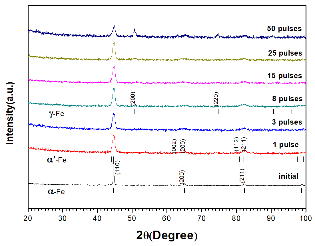
Figure 5 shows the XRD diffraction pattern of grazing incident on the sample surface before and after HCPEB treatment. The results prove that the modified surface is composed of austenitic and martensitic phases. The diffraction peak intensity of the newly formed γ -fe phase increased with the increasing pulse number, and γ -fe phase became the dominating phase of the modified surface layer.
The XRD peaks of the original samples correspond to the diffraction peaks of a single pattern α -Fe phase, and the diffraction peaks are sharp. After HCPEB treatment, XRD diffraction peaks become dull and wider. After three pulses HCPEB treatment, it can be found that the diffraction peaks corresponding to (200) and (211) crystal planes show obvious peak cleavage by observing the diffraction spectra. In general, such diffraction peak cleavage can be seen in the XRD spectra of newly formed martensite. Refer to standard PDF CARDS of martensite ( α -Fe) diffraction spectrum and SEM appearance (Figure 5) of electron beam modification quenched and tempered 40CrNiMo7 steel microstructure, it can be deduced that after HCPEB treatment, with the rapid melting, cooling and solidification process on the sample surface, the surface modification layer of quenched and tempered 40CrNiMo7 steel sample will appear large-scale grain refining and martensite phase transformation. As the number of pulses increased to eight, significant new phase diffraction peaks appeared in the diffraction pattern, corresponding to the diffraction peaks of austenitic phase ( γ -fe) in the standard PDF card. In addition, with the increase of pulse number, the diffraction peak intensity of γ -fe increases gradually, which is proved by the XRD diffraction peak intensity of the modified surface after 50 pulses HCPEB treatment as shown in the figure.
TEM micrograph (Figure 6a) shows that these carbides appear as long shapes and with black contrast due to high carbon content, and with sizes ranging from 1.10 to 0.25 μ m embedded in α -Fe. After one pulse HCPEB treatment, as shown in Figure 6b,c, the newly formed lath martensite and acicular martensite in the modified surface layer can be clearly observed. In addition, the size of carbide particles in the original structure was significantly reduced, as shown in Figure 6d. The results show that the rapid heating of the quenched 40CrNiMo7 steel by initial HCPEB treatment results in surface melting. When the liquid metal became cool and crystallized, the atomic diffusion occurred at first, and the melting locations were where the carbides dissolved. Subsequently, the rapid cooling rate induced the martensitic transformation in the surface-modified layer.
After eight pulse HCPEB treatments, as shown in Figure 6e, the modified area of the sample became more flat and dense, and the microstructure characteristics corresponding to martensitic transformation are even less. The analysis results of the electron diffraction SAED (Figure 6f) shows that the refined grains are austenitic phase and located near the modified surface, which matched the X-ray diffraction analysis results. With more HCPEB treatments, the carbides were fully melted and dissolved.
After 50 times HCPEB treatments, The carbide particles basically disappeared in the modified surface as shown in Figure 6g, and the modified surface composition was evenly distributed, SAED analysis results show that (Figure 6h) the microstructure of the modified surface was compound phase structure consists of austenitic phase and a small amount of nano martensite phase composition, this result is consistent with grazing incidence XRD analysis results (Figure 5). Researches show that even though the cooling rate during the electron beam process can reach up to 10 8 10 9 ks - 1 , the ultrafine grain size in the austenitic phase and the large amount of dissolved alloying elements still inhibit the normal martensitic phase transition. F. Meyers et al. [21] found that nanostructures appeared in the shear zone of 304 stainless steel in the study of high-speed deformation with strain rate up to 10 4 s - 1 , and F. Meyers believed that rapid heating and cooling in the shear zone was conducive to the formation of non-equilibrium structures.

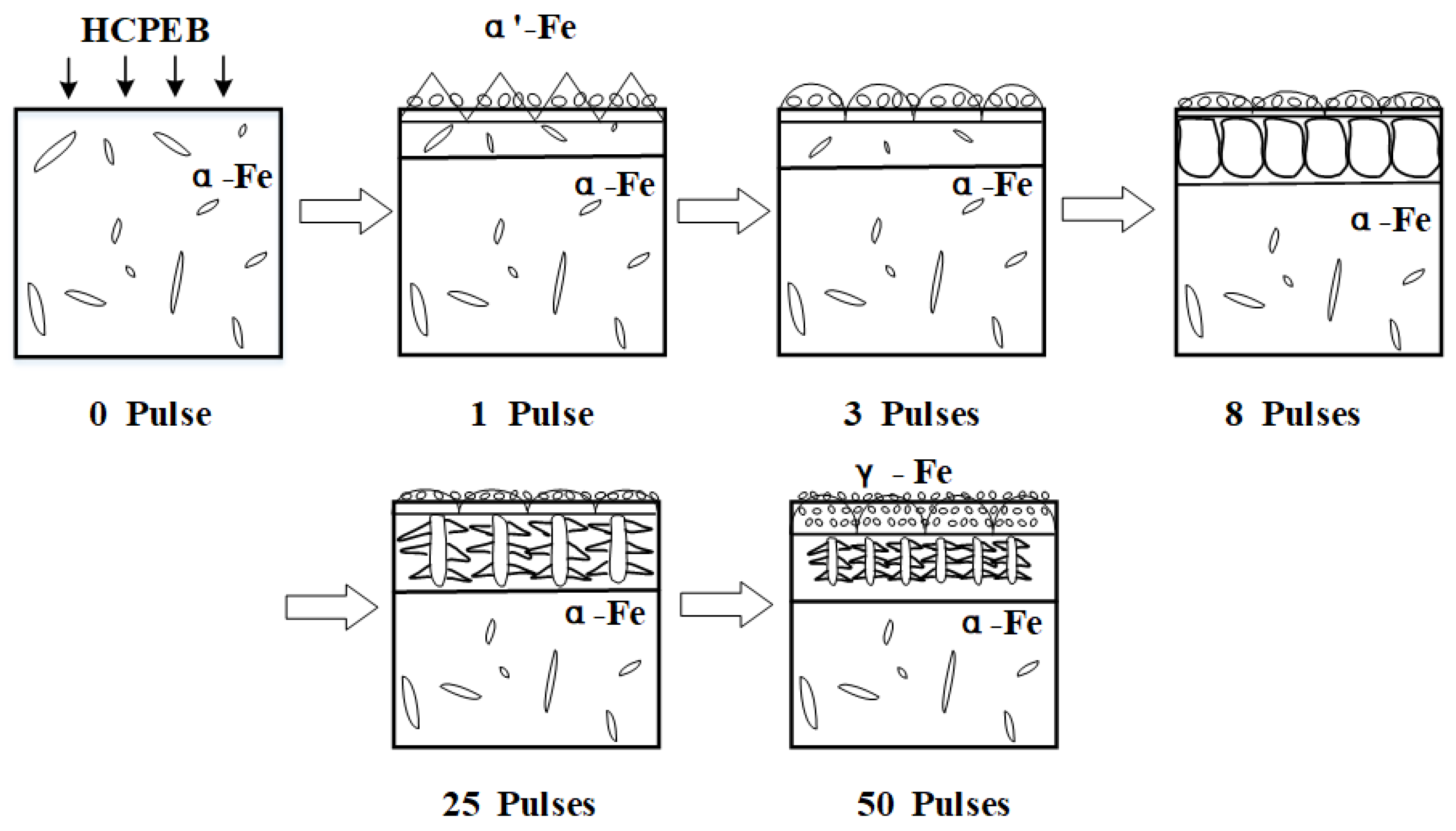
3.3. Microstructure Evolution of Modified Layer

The surface modification mechanism of HCPEB of quenched and tempered 40CrNiMo7 steel is summarized as follows: the surface of the sample melted after irradiation of electron beam. Due to the self-cooling effect of the matrix, solid–liquid interface exists, and liquid metal firstly nucleated at the solid-liquid interface junction. After initial pulse treatment, the modified surface carbide partially melted, and the molten liquid metal in the remelting layer presented greater condensate depression, the molten layer was shallow, and the cooling rate was very high. In this case, the nucleation rate is extremely high, accompanied by the martensite phase transformation and the formation of ridge topography, which were shown in the ridge shape and fine grain in Figure 7 (1 pulses). With the increase of pulse number, the remelting layer deepening continuously and the melt carbides dissolve more fully, meanwhile, carbon atoms were fully dissolved and spread, the nucleation rate increase gradually. The generated nanometer austenitic organization became slighter, and the nanoscale grain inhibited the occurrence of martensite phase transformation. The modified ridge shape surface morphology became more round, this is because extreme shear stress was needed during the martensite phase transformation, whereas it is not possible to overcome the stress disorder in the process of HCPEB treatments. The cooling rate in the remelting layer was gradually reduced, thus the grains could grow along the opposite direction of heat dissipation, and then extended into the liquid solution and eventually formed columnar crystals, which can be proved by the parallel-aligned columnar crystal in the remelting layer as shown in Figure 7 (8 pulses). When the cooling rate continues to reduce, columnar dendrites might generate in the remelting layer, as shown in Figure 7 (25 pulses). After 50 times HCPEB treatments, almost all surface carbides melted, when the cooling rate decreased to a certain extent, the melt which located in front of the columnar dendrites became subcooled and may independently nuclear and growth in the liquid phase, ultimately turned into nanometer isometric when contacting other crystal nuclei, as shown in Figure 7 (50 pulses).

3.4. Corrosion Property

Figure 8a shows typical potentiodynamic polarization cures of 40CrNiMo7 steel recorded in the NaCl (3.5%) solution before and after HCPEB treatment. The corrosion potentials E c o r r of HCPEB treated samples shift indifferently as compared with the initial sample. While the self- corrosion current density ( I c o r r ) and corrosion rate decreases significantly. After 25 pulses of HCPEB treatment. The result indicated the significant improvement on corrosion resistance of the alloying samples the I c o r r value was reduced greatly from the initial 10 . 097 to 2.2099 μ A/cm 2 as shown in Figure 8b, according to the inverse relationship between the corrosion resistance ( R p ) and the Icorr, the R p of treated samples would be improved. Correspondingly, the corrosion rate was decreased drastically from the initial 0.12 to 0.02 mm/a given in Figure 8c. However, the surface corrosion resistance of the samples decreased slightly after 50 pulses of HCPEB treatment.
The unbalanced electrochemical distribution on the material surface leads to the potential difference and forms corrosion microbattery. The surface roughness and the microstructure inhomogeneity of the material surface will lead to unbalanced electrochemical distribution. Li [22] illustrated that surface roughness accelerated the corrosion process of material surface. Three possible mechanisms that increased corrosion resistance can be concluded as follows:
  • The selective purification of the sample surface and the homogenization of the modified surface components by HCPEB effectively reduced the generation probability of the microbattery on material surface;
  • Refined grain structure in modified layer and compact and smooth of surface effectively reduce the direct contact between the material and the corrosive medium, meanwhile, intergranular corrosion is also reduced;
  • The reduction of surface roughness effectively reduces the corrosion rate of the material surface.
Optimal performance of the material surface corrosion resistance was obtained after 25 pulses of HCPEB treatment, which mainly attributed to the generation of the austenitic phase with high alloy content.

4. Conclusions

In this paper, the modification mechanism of the surface microstructure of quenched and tempered 40CrNiMo7 steel modified by HCPEB was studied, and the transformation mechanism of ferrite and cementite during the rapid melting and solidification of the surface was revealed. The most significant advantage of HCPEB surface modification technology is that a new layer form on the surface of the material which is significantly superior to the original material in terms of mechanical and physical properties without changing the composition of the material. Considering the experimental results of material surface structure changes and surface properties before and after HCPEB treatment, we concluded that after intense electron beam irradiation, the surface roughness of the modified material decreased and became smoother and dense. The surface composition was more uniform and the tissue was refined, hence the surface performance was significantly improved. The improvement of corrosion resistance is mainly due to the decrease of surface roughness and the generation of high alloy austenitic phase in the modified surface. The above experimental results show that the HCPEB can serve as a potential technology for the surface modification of low-alloy high-strength steel, thereby improving the surface mechanical properties accordingly.

Author Contributions

H.W. drafted the manuscript and was responsible for the interpretation of the results; L.L. was responsible for project management; S.Q. made contributions to data analysis; W.Z. and Q.L. completed the manuscript proofreading and revision; S.H. performed the experiments and was responsible for equipment configuration; All authors have edited, reviewed and improved the manuscript. All authors have read and agreed to the published version of the manuscript.

Funding

This work was jointly supported by Natural Science Foundation of China under Grant No. 11975002 and 51471043, and the Liaoning Key R&D Guidance Project Grant 2019-BS-011. The authors would like to express their thanks to these funding bodies.

Conflicts of Interest

The authors declare no conflict of interest.

Abbreviations

The following abbreviations are used in this manuscript:
HCPEBHigh-current pulsed electron beam
SEMScanning electron microscopy
TEMTransmission electron microscopy
XRDX-ray diffraction
EBSDElectron back-scattered diffraction
EPMAElectron probe micro analysis

References

  1. Zhang, Y.; Yu, F.; Hao, S.; Dong, F.; Xu, Y.; Geng, W. Evolution of Nanostructure and Metastable Phases at the Surface of a HCPEB-Treated WC-6 % Co Hard. Coatings 2017, 7, 178. [Google Scholar] [CrossRef] [Green Version]
  2. Ormanova, M.; Petrov, P.; Kovacheva, D. Electron beam surface treatment of tool steels. Vacuum 2017, 135, 7–12. [Google Scholar] [CrossRef]
  3. Xia, H.; Zhang, C.; Lv, P.; Cai, J.; Jin, Y.; Guan, Q. Surface alloying of aluminum with molybdenum by high-current pulsed electron beam. Nucl. Inst. Methods Phys. Res. B 2018, 416, 9–15. [Google Scholar] [CrossRef]
  4. Gao, B.; Li, K.; Xing, P. Formation of a Double-Layer Ultrafine Crystal Structure for High-Current Pulsed Electron. Coatings 2019, 9, 413. [Google Scholar] [CrossRef] [Green Version]
  5. Hao, S.; Zhao, L.; Zhang, Y.; Wang, H. Improving corrosion and wear resistance of FV520B steel by high current pulsed electron beam surface treatment. Nucl. Instrum. Methods Phys. Res. Sect. B Beam Interact. Mater. Atoms 2015, 356–357, 12–16. [Google Scholar] [CrossRef]
  6. Peng, W.; Hao, S.; Chen, J.; Li, W.; Zhao, L.; Deng, J. Surface composite microstructure and improved mechanical property of YG10X cemented carbide induced by high current pulsed electron beam irradiation. Int. J. Refract. Met. Hard Mater. 2019, 78, 233–239. [Google Scholar] [CrossRef]
  7. Hao, S.; Wang, H.; Zhao, L. Surface modification of 40CrNiMo7 steel with high current pulsed electron beam treatment. Nucl. Instrum. Methods Phys. Res. Sect. B Beam Interact. Mater. Atoms 2016, 368, 81–85. [Google Scholar] [CrossRef]
  8. Hao, S.; Wang, H.; Li, X.; Yang, W. Design and experimental study of Penning discharge plasma anode for high current pulsed electron beam source. Vacuum 2016, 127, 61–64. [Google Scholar] [CrossRef]
  9. Grosdidier, T.; Zou, J.X.; Stein, N.; Boulanger, C.; Hao, S.Z.; Dong, C. Texture modification, grain refinement and improved hardness/corrosion balance of a FeAl alloy by pulsed electron beam surface treatment in the “heating mode”. Scr. Mater. 2008, 58, 1058–1061. [Google Scholar] [CrossRef]
  10. Lu, J.; Hao, S.; Chen, J.; Zhao, L.; Hu, F. Design and experimental study of high-voltage pulsed penning discharge source with grid electrode. Vacuum 2019, 169, 108940. [Google Scholar] [CrossRef]
  11. Hao, S.; He, D.; Li, M.; Xu, Y.; Dong, C. Enhanced surface properties induced by high current pulsed electron beam (HCPEB) treatment. Mater. Sci. Forum 2011, 675–677, 178–180. [Google Scholar] [CrossRef]
  12. Lou, C.; Zhang, L.; Lu, X.; Lyu, X.; Jin, G.; Wang, Q. Effects of High Current Pulsed Electron Beam Irradiation on the Mechanical Properties and Cutting Performance of TiAlN-Coated Tools. J. Mater. Eng. Perform. 2017, 26, 5864–5870. [Google Scholar] [CrossRef]
  13. Zhang, C.; Lv, P.; Xia, H.; Yang, Z.; Konovalov, S.; Chen, X.; Guan, Q. The microstructure and properties of nanostructured Cr-Al alloying layer fabricated by high-current pulsed electron beam. Vacuum 2019, 167, 263–270. [Google Scholar] [CrossRef]
  14. Wei, D.; Wang, X.; Wang, R.; Cui, H. Surface modi fi cation of 5CrMnMo steel with continuous scanning electron beam process. Vaccum 2018, 149, 118–123. [Google Scholar] [CrossRef]
  15. Jerez-Mesa, R.; Travieso-Rodríguez, J.; Landon, Y.; Dessein, G.; Lluma-Fuentes, J. Comprehensive analysis of surface integrity modification of ball-end milled Ti-6Al-4V surfaces through vibration-assisted ball burnishing. J. Mater. Proc. Tech. 2019, 267, 230–240. [Google Scholar] [CrossRef]
  16. Cai, J.; Gao, C.; Lv, P.; Zhang, C.; Guan, Q. Hot corrosion behaviour of thermally sprayed CoCrAlY coating irradiated by high-current pulsed electron beam. J. Alloys Compd. 2019, 784, 1221–1233. [Google Scholar] [CrossRef]
  17. Lv, P.; Sun, X.; Cai, J.; Zhang, C.; Liu, X.; Guan, Q. Microstructure and high temperature oxidation resistance of nickel based alloy GH4169 irradiated by high current pulsed electron beam. Surf. Coat. Technol. 2017, 309, 401–409. [Google Scholar] [CrossRef]
  18. Cai, J.; Guan, Q.; Lv, P.; Zhang, C.; Yin, Y. Crater Formation on the Surface of Pure Metal and Alloy Irradiated by High Current Pulsed Electron. High Temp. Mater. Proc. 2018, 37, 777–784. [Google Scholar] [CrossRef]
  19. Guan, Q.F.; Zou, H.; Zou, G.T.; Wu, A.M.; Hao, S.Z.; Zou, J.X.; Qin, Y.; Dong, C.; Zhang, Q.Y. Surface nanostructure and amorphous state of a low carbon steel induced by high-current pulsed electron beam. Surf. Coat. Technol. 2005, 196, 145–149. [Google Scholar] [CrossRef]
  20. Wang, Q.; Wang, Y.; Wang, H.; Fan, N.; Yan, F.; Wang, Q.; Wang, Y.; Wang, H.; Fan, N.; Yan, F. Fretting Wear Behavior of UHMWPE Under Different Temperature Conditions Fretting Wear Behavior of UHMWPE Under Different. J. Macromol. Sci. Part B Phys. 2017, 56, 493–504. [Google Scholar] [CrossRef]
  21. Meyers, M.; Xu, Y.; Xue, Q.; Perez-Prado, M.; McNelley, T. Microstructural evolution in adiabatic shear localization in stainless steel. Acta Mater. 2003, 51, 1307–1325. [Google Scholar] [CrossRef]
  22. Li, W.; Li, D. Influence of surface morphology on corrosion and electronic behavior. Acta Mater. 2006, 54, 445–452. [Google Scholar] [CrossRef]
Figure 1. Typical surface optical microscope (OM) and scanning electron microscope (SEM) of quenched and tempered 40CrNiMo7 steel before (a) and after (b,c) high-current pulsed electron beam (HCPEB) irradiation with one pulse.
Coatings 10 00311 g001
Figure 2. The surface roughness of quenched and tempered 40CrNiMo7 steel under HCPEB treadment with different pulses number.
Coatings 10 00311 g002
Figure 3. SEM surface morphology of 40CrNiMo7 steel after HCPEB treatment with 3 pulses (a,b), 15 pulses (c,d), and 50 pulses (e,f).
Coatings 10 00311 g003
Figure 4. Cross-sectional SEM morphology of quenched and tempered 40CrNiMo7 steel with different pulses 1 pulse (a), 3 pulses (b), 8 pulses (c,d), 15 pulses (e), 25 pulses (f,g) and 50 pulses (h,i).
Coatings 10 00311 g004
Figure 5. GAXRD ( θ - 1 ) of quenched and tempered 40CrNiMo7 steel before and after HCPEB irradiation.
Coatings 10 00311 g005
Figure 6. Transmission electron microscope (TEM) bright field image of quenched and tempered 40CrNiMo7 steel before (a) after HCPEB irradiation (bd) 1 pulse, (e,f) 8 pulses, and (g,h) 50 pulses; (f,h) the selected area electron diffraction (SAED) pattern were given inset, respectively.
Coatings 10 00311 g006
Figure 7. Schematic of modified layer of electron beam irradiated 40CrNiMo7 steel.
Coatings 10 00311 g007
Figure 8. (a) Polarization curves, (b) self-corrosion current density, (c) corrosion rate of 40CrNiMo7 steel before and after HCPEB irradiation.
Coatings 10 00311 g008
Table 1. The chemical compositions of quenched and tempered 40CrNiMo7 steel (wt%).
CCrNiMoMnSiFe
0.390.731.690.240.670.25Balance

