Abstract
Recently, heterogeneous structured semiconductor photocatalysts have received significant interest in promoting global cleaning from the environmental pollution. Herein, we report the synthesis of graphene oxide (GO) wrapped zinc oxide (ZnO) core–shell nanofibers (ZnO@G CSNFs) by the simple core–shell electrospinning and subsequent annealing for efficient photocatalytic performance and stability. The heterostructured catalyst consisted of ZnO forming an enclosed core part while the GO was positioned on the surface, serving as a protective shell. Field emission scanning electron microscopy, high-resolution transmission electron microscopy and X-ray diffraction were used to confirm the synthesis of the desired product. Enhanced photocatalytic activity ZnO@G CSNFs was found compared to the corresponding ZnO NFs. Similarly, incorporation of GO into the ZnO nanofiber in a core–shell format significantly suppressed the photocorrosion. This study highlights the usefulness of using GO as the coating material to boost the photocatalytic performance of ZnO-based photocatalysts.
1. Introduction
At a global scale, environmental pollution has become a major problem, as current levels may already exceed globally sustainable limits. Therefore, huge investments tipped on research and development to attain reliable and efficient environmental purification technology. However, environmental pollution has progressed considerably and unstoppably for the time being due to ever-increasing industrial waste, air pollution, water pollution, etc., which cause wide public concerns [1]. Creative production of materials such as plastic fibers from waste, plywood from coffee powder or grain shell, and light oil from vinyl pyrolysis is ongoing as a purification strategy [2]. These approaches alone may not be sufficient to mitigate a fundamental concern. Accordingly, there is a need for an environmental purification technology that has little or no maintenance cost. A representative technology that meets this requirement is the application of photocatalysts [3,4,5,6,7,8]. Photocatalysts show tremendous potentials for degradation of toxic contaminants and dyes, and they are recognized as one of the most efficient means to solve the issue of environmental pollution [9].
Zinc oxide is an n-type metal oxide semiconductor with a large bandgap (3.37 eV) and high excitation binding energy (60 eV) [10]. Zinc is an abundantly available metal, inexpensive, and environmentally friendly. Moreover, it has a strong photo-induced hole oxidation ability in addition to antimicrobial properties. Therefore, ZnO has been extensively used in the photocatalytic degradation of organic pollutants [6,11,12,13,14,15]. However, ZnO has been reported to suffer from performance degradation due to the light-induced photocorrosion [16]. Since high mechanical integrity and chemical stability are the prerequisites for real applications, developing a stable active catalyst from cheap and abundant ZnO is important to achieve [17].
To date, several efforts have been made to restrain the photo-induced instability of ZnO-based composites. The most common way of solving photo/electrochemical instability of ZnO-based catalysts is coating them with carbon materials due to their excellent stability [9,18,19]. Fabrication of a ZnO-based photocatalyst with a combination of carbons including activated carbon, carbon nanotubes, and fullerene in a core@shell format can not only improve the rate of charge separation but also prevent photocorrosion [20,21,22]. Graphene, a two-dimensional material, has been spotlighted as an application material in many fields due to its unique characteristics such as excellent charge carrier ability, high light transmittance, and large surface area [19,23,24,25]. Therefore, it is an ideal candidate to couple with ZnO to obtain a composite with improved photocatalytic performance [26,27,28,29,30,31,32,33,34,35,36].
Several works have shown core–shell ZnO@graphene compositions in the particle format and use in photocatalysis [37,38,39]. In general, photocatalysts are in particle form, which tends to aggregate. Most importantly, the recoverability of photocatalyst and purification process is hampered severely due to possibility of making a slurry with polluted materials [40]. To achieve a high degree of utilization of photocatalyst for an extended period, immobilization on fibrous sheet-typed materials with a large surface has often been employed [41]. Electrospinning is a cost-efficient and simple technique for fabricating network-like fibrous sheets that have been studied in many fields because of their high specific surface area and mesoporous structure. These fibers have also been used as the template for the synthesis of fiber-type material [42,43]. The photocatalysis performance of fibrous samples containing photocatalytic compounds can be severely hampered due to bulky support materials, which do not show photocatalytic property. In this scenario, removing the fiber as a template results in the synthesis of pure photocatalysts as a self-supported material in a fiber form. Several studies have shown that fibers and rods have better photocatalytic performances than pure particles because of their superior surface area and aspect ratio [9]. From the above-mentioned concerns, the novelty of this work can be summarized as the synthesis of controlled core–shell-type nanofibers in which ZnO resides in the core part while graphene forms the sheath that contributes to preventing the photocorrosion of ZnO. We fabricated graphene wrapped ZnO nanofibers by core–shell electrospinning method. Then, the polymeric matrix was removed by annealing, thereby obtained the ZnO@G core–shell nanofibers (ZnO@G CSNFs). Finally, physiochemical properties and photocatalytic performances of the as-prepared composite were investigated. The results show as-synthesized core–shell nanofibers had excellent performance with no loss due to the photocorrosion. The graphene as a shell played a role in enhancing the performance by preventing photocorrosion.
2. Experimental
2.1. Chemicals
Zinc acetate dihydrate [Zn(CH3CO2)2∙2H2O, ≥98%], hydrogen peroxide (35 wt.%, in water), sodium nitrate (NaNO3, ≥99%), graphite (particle size <50 μm, ≥99.5%), and polyvinylpyrrolidone (PVP, average molecular weight (Mn) 1,300,000)) were purchased from Sigma-Aldrich (Jeonju, Korea). Sulfuric acid (H2SO4, 95%) and N,N-Dimethylformamide (DMF, 99%) were purchased from Samchun, Jeonju, Korea. Methylene blue dihydrate (C16H18ClN3S∙2H2O, 95%) and potassium permanganate (KMnO4, 99.3%) were obtained from Showa (Jeonju, Korea).
2.2. Synthesis of Graphene Oxideok
Graphite powder was used to prepare graphene oxide by the Hummers method [44]. First, 50 mL of sulfuric acid were added carefully to the ice-cold flask, then 1 g of graphite powder was added slowly, and it was stirred for about 1 h. Then, 1 g of sodium nitrate was added and stirred for another 3 h. At this time, the ice was replenished before it melted. After obtaining a homogenized mixture, 6 g of potassium permanganate were added slowly. The mixture solution was removed from the ice bath and stirred overnight. Then, 100 mL of water were slowly added dropwise. At this time, the color of the mixture solution turned dark brown. After 30 min, 500 mL of water were added, it was stirred for about 3 h, and 20 mL of hydrogen peroxide were further added. Next, the solution was centrifuged (15,000 rpm, 40 min) and washed several times with water and ethanol. The as-obtained graphene oxide was dried overnight at 60 °C.
2.3. Fabrication of ZnO Nanofibers (ZnO NFs) by Electrospinning
To prepare the typical electrospun solution, 2.5 g ZnAc and 5.0 g PVP were added to 10 g of DMF, and the solution was stirred overnight to dissolve. To fabricate ZnO nanofibers, the ZnAc/PVP was subjected to electrospinning at the rate of 0.01 mL/min using the single nozzle. During the electrospinning, the voltage was maintained at 15 kV and the distance between the nozzle and the collector was maintained at 15 cm. The fabricated ZnAc/PVP nanofibers were transferred to ceramic bowl and calcined in air at 450 °C for 3 h to convert ZnAc to ZnO in nanofibers.
2.4. Fabrication of ZnO@G Core@shell Nanofibers (ZnO@G CSNFs)
The solution used to prepare core part, i.e., ZnO, was prepared as mentioned above. To prepare the shell electrospun solution, a different amount of GO (0 wt.%–3 wt.% of ZnAc) was added to 10 g of DMF and dispersed for 6 h using sonication. When dispersion was completed, 2.5 g of PVP were added to the solution, and the solution was stirred overnight to dissolve. To fabricate ZnO@G CSNFs, the ZnAc/PVP solution and GO/PVP solution were subjected to electrospinning at the rate of 0.01 mL/min on the core and shell side, respectively, using the core@shell nozzle. During the electrospinning, the voltage was maintained at 15 kV, and the distance between the nozzle and the collector was maintained at 15 cm. The fabricated ZnAc@GO/PVP nanofibers were transferred to a ceramic bowl and calcined in air at 450 °C (unless otherwise noted) for 3 h, to convert ZnAc to ZnO in nanofibers. The nanofiber samples prepared by using GO 0%, 0.5%, 1%, 2%, and 3% of ZnAc are referred to as Zno NFs, ZnO@G0.5 CSNFs, ZnO@G1 CSNFs, ZnO@G2 CSNFs, and ZnO@G3 CSNFs, respectively. For the comparative study, general ZnO/G fibers were formed by electrospinning of the blend of ZnO precursor and GO with PVP by a single nozzle (no core–shell). The GO was used 2 wt.% of Zn precursor. As formed nanofibers were referred to as ZnO@G2 NFs.
2.5. Characterization
The crystallinity of the as-fabricated core@shell nanofibers was studied by X-ray diffraction (XRD, MAX-2500, Rigaku, Japan). The morphology of the nanofibers was observed by field emission scanning electron microscopes (FE-SEM, SUPRA40VR, Zeiss, Oberkochen, Germany) and high-resolution transmission electron microscopy (HR-TEM, JEM-2200FS, JEOL, Tokyo, Japan). The basic composition of nanofibers was confirmed by an energy-dispersive X-ray spectrometer (EDS, SUPRA40VR, Zeiss, Oberkochen, Germany).
2.6. Photodegradation Measurement
To measure the photocatalytic properties of the ZnO NFs and ZnO@G CSNFs, methylene blue (MB) solution was used under ultraviolet (UV) irradiation according to previously established work [45]. For the photocatalyst experiment, VL-6.LC (24 W, Vilber, Eberhardzell, Germany) UV lamp was used for the degradation of dye. The photocatalytic performance was measured by adding 0.5 g nanofibers into 500 mL of an MB solution of a concentration of 10 mM. Before the measurement, air bubbles were removed using a vacuum.
At different time intervals, 1 mL of the solution containing the sample was centrifuged and the concentration of remaining/degraded MB was analyzed by a spectrophotometer (Perkin Elmer, Shelton, CT, USA). The stability of the samples was studied for three consecutive cycles in the same condition. The degradation of MB was calculated by measuring the concentration of MB before and after the test using the following equation:
where η is the photocatalytic efficiency; C0 is the initial concentration of MB; and Ct is the concentration of MB after t minutes of UV light irradiation. Moreover, the photocorrosion percentage (%) was calculated according to Equation (2) [9].
3. Results and Discussion
Scheme 1a,b shows the general electrospinning process of ZnAc/PVP to obtain the ZnO/PVP nanofibers using a single nozzle. Similarly, Scheme 1c,d shows the process of synthesis of ZnO@G CSNFs using the core@shell nozzle. For the core–shell nanofibers, ZnAc/PVP solution was used for the core part and GO/PVP solution was used for the shell part. As-synthesized nanofibers were annealed to ensure the removal of the PVP by the complete degradation at high temperature while remaining ZnO and ZnO@G CSNFs were obtained from the product using single and core–shell electrospinning, respectively. Annealing brings the Zn precursor to form ZnO by the oxidation of pure metal.
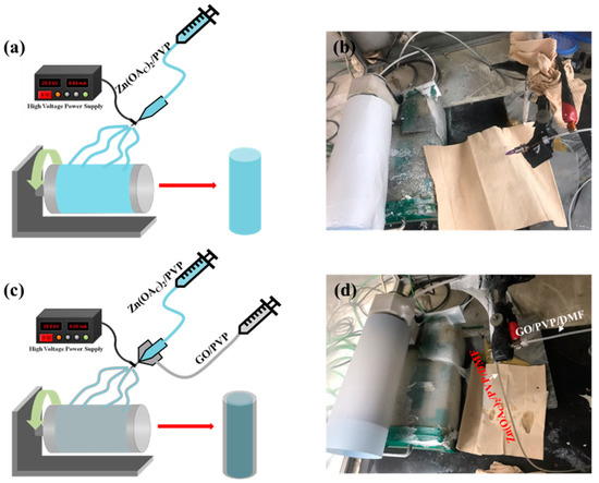
Scheme 1.
Schematic diagram of electrospinning of ZnO NFs (a) and corresponding digital image (b). (c,d) The schematic diagram of the electrospinning of core@shell fibers and corresponding digital image, respectively.
Figure 1a shows the XRD patterns of ZnO NFs, and ZnO@G CSNFs. The XRD pattern of ZnO NFs showed 2θ at 31.8°, 33.7°, 36.2°, 47.4°, 56.5°, 62.9°, 66.2°, 67.9°, 69.1°, 72.5°, and 77.1°, corresponding to crystal planes (100), (002), (101), (102), (110), (103), (200), (112), (201), (004), and (202), respectively, of ZnO (Joint Committee on Powder Diffraction Standards, JCPDS card No. 36-1451) [46]. The XRD pattern of ZnO@G CSNFs showed all the peaks corresponding to ZnO along with an additional peak at 2θ = 26.6°, attributed to the plane of (002) for the exfoliated graphene [47], suggesting the incorporation of GO on to the core–shell NFs.
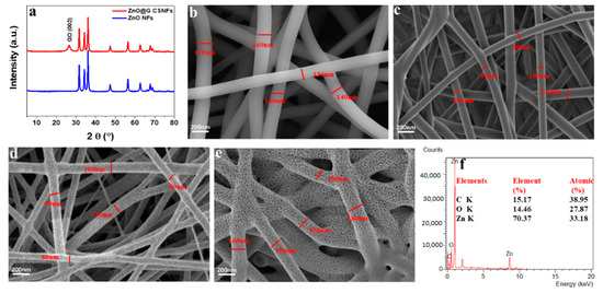
Figure 1.
XRD patterns of ZnO NFs and ZnO@G CSNFs (a); FE-SEM image of ZnAc/PVP/G NFs (b); FE-SEM image of 350 °C/3 h annealed ZnAc/PVP/G CSNFs (c); FE-SEM image of 450 °C/3 h annealed ZnAc/PVP/G CSNFs (d); FE-SEM image of 550 °C/3 h annealed ZnAc/PVP/G CSNFs (e); and SEM-EDS of ZnO@G CSNFs (f).
Figure 1b–e shows the comparison of the morphology of the nanofibers before and after annealing. In the SEM image, ZnAc/G/PVP nanofibers before annealing showed nanofibers with a smooth surface and uniformity in size (average diameter = 152 ± 25 nm) (Figure 1b). Figure 1b–e shows that the nanofibers of ZnO@G CSNFs obtained from the annealing at different temperature. The results show that the diameter of annealed nanofibers decreases gradually as the temperature increases up to 450 °C. The nanofibers with a size of 100 ± 15 nm maintain a smooth surface at 350 °C/3 h (Figure 1c), but nanofibers were found coated with nanoparticles when annealed at 450 °C (Figure 1d). However, the morphology of nanofibers begins to collapse (Figure 1e), as indicated by the flattening of the nanofiber structure, in the case of annealing at 550 °C. EDX spectra analysis exhibited the ZnO@G CSNFs contained Zn, C, and O at 70.3 wt.%, 15.1 wt.%, and 14.4 wt.%, respectively.
Figure 2a shows the pure ZnO NFs consisting of uniform particles of 30–50 nm. A high-resolution image showed the 0.26-nm lattice, corresponding to (002) planes of ZnO (Figure 2b). As-obtained exfoliated graphene oxide sheets are shown Figure 2c. Figure 2d,e shows the TEM images of ZnO@G core@shell NFs. The images show that ZnO/GO NFs also consisted of nanoparticles, similar to the pure ZnO NFs. A close look at high magnification revealed that GO formed the outer shell layer encapsulating ZnO particles (Figure 2e), thus confirming the synthesis of core–shell NFs. Figure 2f shows the EDS mapping results of ZnO NFs. It was thus concluded that the core–shell nanofiber was comprised of the Zn, O, and C.
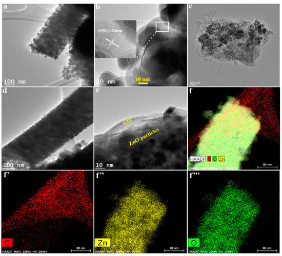
Figure 2.
TEM images of ZnO NF (a); magnified image of ZnO particles on ZnO NF (b), GO (c), and ZnO@G CSNF (d); magnified image of ZnO@G CSNF (e); and elemental mapping images of ZnO@G CSNF (f): (f’) C; (f’’) Zn; (f’’’) O.
The photocatalytic decomposition of MB was performed to confirm the photocatalytic performance of the nanofibers. It was performed in a dark chamber to block other external stimuli, and the amount of UV light was maintained identically in all cases. Figure 3a shows the photocatalytic performance of ZnO@G CSNFs with different GO concentrations. In general, as the content of GO increased, the photocatalytic performance of ZnO@G nanofibers increased, as shown by a uniform MB reduction rate (Figure 3a). The core–shell nanofibers showed superior degradation up to ~97% for ZnO@G2 CSNFs compared to the lower 32% and 24% for ZnO@G2 and ZnO NFs, respectively, in the same period. The degradation rates of the ZnO@G2 and ZnO@G3 CSNFs were similar. Figure 3b shows the change in the UV–vis absorption spectrum of the MB solution by ZnO@G2 CSNFs. The results exhibit that the absorbance became almost zero for ZnO@G2, indicating the complete decomposition of MB within 2 h. The gradual decreasing intensity of the MB color of ZnO@G2 CSNF-treated sample in real-time, as indicated by the digital images (Figure 3b, inset), further supported the result of UV–vis absorbance data. To confirm the reusability and durability of core–shell nanofibers, a photocatalytic degradation cycle experiment of ZnO@G2 CSNFs was conducted. Three cycles were performed under UV conditions, and the results are presented in Figure 3c. The results show the photocatalytic performance remained almost identical during three consecutive cycles, suggesting the ZnO@G CSNFs were well stable for prolonged working periods. Many reports state that the performance of catalytic activity of ZnO decays quickly due to it suffering from the photocorrosion effect under UV light [44,48]. Therefore, it is necessary to understand whether the incorporation of GO improved the photo-induced corrosion of ZnO. Thus, we studied the photocorrosion property of the main material and compared it with the pure ZnO and ZnO@G2 NFs by studying photodegradation for a number of cycles. The results show the ZnO@G CSNFs were well stable for extended cycles, unlike the ZnO@G2 and ZnO NFs, for which photocatalytic activity was reduced from 76% to 68% and 68% to 55%, respectively, between the first and third cycles. To discuss quantitatively, the photocorrosion percentage (%) was calculated according to Equation (2).
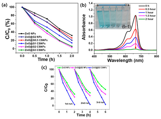
Figure 3.
Photocatalytic degradation of MB by different samples under UV light (a); UV–vis absorbance of MB solution treated with ZnO@G2 CSNFs under UV light for 2 h (b), where the inset shows digital image of the samples showing color changes in a real-time (b-1); and photocatalytic degradation cycles of different samples (c).
The photocorrosion percentages for ZnO NFs, ZnO@G2 NFs, and ZnO@G CSNFs were 19.1% 10.5%, and 0.8%, respectively. The fast performance degradation of ZnO NFs can be explained by the fast expulsion of the Zn2+ ions into the solution due to reaction of holes and unsaturated oxygen atoms. The photocorrosion process of ZnO can be represented by the reaction: ZnO + 2h+ → Zn2+ + 1/2O2. However, for the combination of ZnO and graphene nanosheets in a core–shell fashion, the photocorrosion process was significantly suppressed by 18%, suggesting the GO shell is able to protect the ZnO from being photo-corroded. This is attributed to the combination of GO and the surface unsaturated oxygen atoms of ZnO. As a result, the number of surface oxygen atoms could be decreased sharply. GO mediates higher adsorption of the MB on the surface of ZnO, which can consume the photo-generated holes and results in direct photo-oxidation of MB due to the action of hydroxyl radicals (OH•) [49]. The ZnO@G2 NFs showed higher photocorrosion than ZnO@G2 CSNFs but lower than ZnO NFs, suggesting the incorporation of GO has a beneficial effect in increasing the stability and lowering the photocorrosion. Moreover, this also clearly indicates that wrapping the ZnO nanofibers by GO is a major strategy to mitigate photocorrosion while increasing photocatalytic stability.
Figure 4 shows the schematic illustration of the mechanism of MB degradation. The electrospun ZnO nanofibers were coated with GO and light-generated carrier diffusion occurred at the interface between them. Similarly, the light generated electrons from the ZnO move to the graphene surface and yield oxygen radicals that decompose MB. Another mechanism of degradation is due to (OH•) radical-mediated photooxidation.
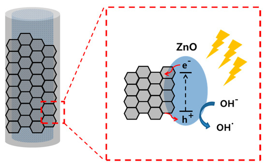
Figure 4.
Schematic diagram showing the internal structure and mechanism of degradation.
4. Conclusions
This paper provides a one-step core–shell nanofiber fabrication by simple electrospinning and post-processing approaches without using harmful chemicals. The as-synthesized nanofibers consisted of pure ZnO as a core-forming material, while graphene was located on the surface of ZnO as a protective shell. MB degradation results show that ZnO@G CSNFs had about 97% degradation compared to 68% for the corresponding ZnO NFs counterpart. ZnO@G CSNFs were found highly stable and had photocorrosion lower than 0.8% compared to higher than 10.5% for ZnO@G2 NFs and 19.1% for ZnO NFs. The superior performance of core–shell nanofibers was attributed to the increasing stability of the composite due to coating of the fragile ZnO nanofibers by the highly stable graphene sheets. These results highlight the hierarchical organization of GO in the enhancement of the ZnO photocatalytic activities. This fabrication method can apply to other photocatalytic materials and ensure efficient removal of organic pollutants and dyes.
Author Contributions
S.M.J.: Conceptualization, methodology, data curation, writing—original draft preparation. A.P.T.: writing—original draft preparation, writing—review and editing and supervision. H.Y.K.: Supervision, project administration, funding acquisition. All authors have read and agreed to the published version of the manuscript.
Funding
This work was supported by the National Research Foundation of Korea (NRF) grant funded by the Korea Government (MSIT) (2019R1A5A8080326) and program for fostering next-generation researchers in engineering (NRF ICT No. 2017H1D8A2030449).
Conflicts of Interest
There is no conflict of interest among authors.
References
- Schwarzenbach, R.P.; Egli, T.; Hofstetter, T.B.; von Gunten, U.; Wehrli, B. Global water pollution and human health. Annu. Rev. Environ. Resour. 2010, 35, 109–136. [Google Scholar] [CrossRef]
- Van der Hoek, J.P.; de Fooij, H.; Struker, A. Wastewater as a resource: Strategies to recover resources from Amsterdam’s wastewater. Resour. Conserv. Recycl. 2016, 113, 53–64. [Google Scholar] [CrossRef]
- Wang, C.-C.; Li, J.-R.; Lv, X.-L.; Zhang, Y.-Q.; Guo, G. Photocatalytic organic pollutants degradation in metal–organic frameworks. Energy Environ. Sci. 2014, 7, 2831–2867. [Google Scholar] [CrossRef]
- Chang, H.; Wu, H. Graphene-Based Nanocomposites: Preparation, functionalization, and energy and environmental applications. Energy Environ. Sci. 2013, 6, 3483–3507. [Google Scholar] [CrossRef]
- Bandara, W.R.L.N.; de Silva, R.M.; de Silva, K.M.N.; Dahanayake, D.; Gunasekara, S.; Thanabalasingam, K. Is nano ZrO2 a better photocatalyst than nano TiO2 for degradation of plastics? RSC Adv. 2017, 7, 46155–46163. [Google Scholar] [CrossRef]
- Yu, Z.; Chouchene, B.; Liu, M.; Moussa, H.; Schneider, R.; Moliere, M.; Liao, H.; Chen, Y.; Sun, L. Influence of laminated architectures of heterostructured CeO2-ZnO and Fe2O3–ZnO films on photodegradation performances. Surf. Coat. Technol. 2020, 403, 126367. [Google Scholar] [CrossRef]
- Zhou, Q.; Su, C.-Y.; Zheng, J.-J. Photocatalytic HA Deposition on TiO2 of Ti–0.2Pd surface immersed in simulated body fluid. Surf. Coat. Technol. 2020, 389, 125649. [Google Scholar] [CrossRef]
- Pant, B.; Park, M.; Park, S.-J. Recent advances in TiO2 films prepared by sol-gel methods for photocatalytic degradation of organic pollutants and antibacterial activities. Coatings 2019, 9, 613. [Google Scholar] [CrossRef]
- Tayebi, M.; Tayyebi, A.; Masoumi, Z.; Lee, B.-K. Photocorrosion suppression and photoelectrochemical (PEC) enhancement of ZnO Via hybridization with graphene nanosheets. Appl. Surf. Sci. 2020, 502, 144189. [Google Scholar] [CrossRef]
- Luo, K.; Li, J.; Hu, W.; Li, H.; Zhang, Q.; Yuan, H.; Yu, F.; Xu, M.; Xu, S. Synthesizing CuO/CeO2/ZnO ternary nano-photocatalyst with highly effective utilization of photo-excited carriers under sunlight. Nanomaterials 2020, 10, 1946. [Google Scholar] [CrossRef]
- Khodja, A.A.; Sehili, T.; Pilichowski, J.-F.; Boule, P. Photocatalytic degradation of 2-phenylphenol on TiO2 and ZnO in aqueous suspensions. J. Photochem. Photobiol. A Chem. 2001, 141, 231–239. [Google Scholar] [CrossRef]
- Rahman, Q.I.; Ahmad, M.; Misra, S.K.; Lohani, M. Effective photocatalytic degradation of rhodamine B dye by ZnO nanoparticles. Mater. Lett. 2013, 91, 170–174. [Google Scholar] [CrossRef]
- Qi, K.; Yu, J. Modification of ZnO-based photocatalysts for enhanced photocatalytic activity. Interface Sci. Technol. 2020, 31, 265–284. [Google Scholar]
- Verbic, A.; Gorjanc, M.; Simoncic, B. Zinc oxide for functional textile coatings: Recent advances. Coatings 2019, 9, 550. [Google Scholar] [CrossRef]
- Sharma, M.; Poddar, M.; Gupta, Y.; Nigam, S.; Avasthi, D.K.; Adelung, R.; Abolhassani, R.; Fiutowski, J.; Joshi, M.; Mishra, Y.K. Solar light assisted degradation of dyes and adsorption of heavy metal ions from water by CuO–ZnO tetrapodal hybrid nanocomposite. Mater. Today Chem. 2020, 17, 100336. [Google Scholar] [CrossRef]
- Fu, H.; Xu, T.; Zhu, S.; Zhu, Y. Photocorrosion inhibition and enhancement of photocatalytic activity for ZnO via hybridization with C60. Environ. Sci. Technol. 2008, 42, 8064–8069. [Google Scholar] [CrossRef]
- Zhu, P.; Nair, A.S.; Peng, S.; Yang, S.; Ramakrishna, S. Facile fabrication of TiO2–graphene composite with enhanced photovoltaic and photocatalytic properties by electrospinning. ACS Appl. Mater. Interfaces 2012, 4, 581–585. [Google Scholar]
- Kim, T.; Tiwari, A.P.P.; Chhetri, K.; Ojha, G.P.; Kim, H.; Chae, S.-H.; Dahal, B.; Lee, B.M.; Mukhiya, T.; Kim, H.Y. Phytic acid controlled in situ synthesis of amorphous cobalt phosphate/carbon composite as anode materials with a high mass loading for symmetrical supercapacitor: Amorphization of the electrode to boost the energy density. Nanoscale Adv. 2020, 2, 4918–4929. [Google Scholar] [CrossRef]
- Politano, G.G.; Vena, C.; Desiderio, G.; Versace, C. Variable angle spectroscopic ellipsometry characterization of reduced graphene oxide stabilized with poly (sodium 4-styrenesulfonate). Coatings 2020, 10. [Google Scholar] [CrossRef]
- Cong, Y.; Long, M.; Cui, Z.; Li, X.; Dong, Z.; Yuan, G.; Zhang, J. Anchoring a uniform TiO2 layer on graphene oxide sheets as an efficient visible light photocatalyst. Appl. Surf. Sci. 2013, 282, 400–407. [Google Scholar] [CrossRef]
- Elizalde-Gonzalez, M.P.; Garcia-Diaz, E.; Sabinas-Hernandez, S.A. Novel preparation of carbon–TiO2 composites. J. Hazard. Mater. 2013, 263, 73–83. [Google Scholar] [CrossRef] [PubMed]
- Rakibuddin, M.; Ananthakrishnan, R. Effective photocatalytic dechlorination of 2, 4-dichlorophenol by a novel graphene encapsulated ZnO/Co3O4 core–shell hybrid under visible light. Photochem. Photobiol. Sci. 2016, 15, 86–98. [Google Scholar] [CrossRef] [PubMed]
- Pu, X.; Zhang, D.; Gao, Y.; Shao, X.; Ding, G.; Li, S.; Zhao, S. One-pot microwave-assisted combustion synthesis of graphene oxide–TiO2 hybrids for photodegradation of methyl orange. J. Alloy. Compd. 2013, 551, 382–388. [Google Scholar] [CrossRef]
- Dutta, M.; Sarkar, S.; Ghosh, T.; Basak, D. ZnO/graphene quantum dot solid-state solar cell. J. Phys. Chem. C 2012, 116, 20127–20131. [Google Scholar]
- Pan, X.; Zhao, Y.; Liu, S.; Korzeniewski, C.L.; Wang, S.; Fan, Z. Comparing graphene–TiO2 nanowire and grapheme–TiO2 nanoparticle composite photocatalysts. ACS Appl. Mater. Interfaces 2012, 4, 3944–3950. [Google Scholar]
- Novoselov, K.S.; Geim, A.K.; Morozov, S.V.; Jiang, D.; Zhang, Y.; Dubonos, S.V.; Grigorieva, I.V.; Firsov, A.A. Electric field effect in atomically thin carbon films. Science 2004, 306, 666. [Google Scholar] [CrossRef]
- Zhang, N.; Zhang, Y.; Xu, Y.-J. Recent progress on graphene-based photocatalysts: Current status and future perspectives. Nanoscale 2012, 4, 5792–5813. [Google Scholar] [CrossRef]
- Low, J.; Yu, J.; Ho, W. Graphene-based photocatalysts for CO2 reduction to solar fuel. J. Phys. Chem. Lett. 2015, 6, 4244–4251. [Google Scholar] [CrossRef]
- Yang, S.; Li, W.; Ye, C.; Wang, G.; Tian, H.; Zhu, C.; He, P.; Ding, G.; Xie, X.; Liu, Y.; et al. C3N—A 2D crystalline, hole-free, tunable-narrow-bandgap semiconductor with ferromagnetic properties. Adv. Mater. 2017, 29, 1605625. [Google Scholar] [CrossRef]
- Xiang, Q.; Yu, J.; Jaroniec, M. Preparation and enhanced visible-light photocatalytic H2-production activity of graphene/C3N4 composites. J. Phys. Chem. C 2011, 115, 7355–7363. [Google Scholar] [CrossRef]
- He, G.-L.; Zhong, Y.-H.; Chen, M.-J.; Li, X.; Fang, Y.-P.; Xu, Y.-H. One-pot hydrothermal synthesis of SrTiO3-reduced graphene oxide composites with enhanced photocatalytic activity for hydrogen production. J. Mol. Catal. A Chem. 2016, 423, 70–76. [Google Scholar] [CrossRef]
- Kavitha, T.; Gopalan, A.I.; Lee, K.-P.; Park, S.-Y. Glucose sensing, photocatalytic and antibacterial properties of graphene–ZnO nanoparticle hybrids. Carbon 2012, 50, 2994–3000. [Google Scholar] [CrossRef]
- Akhavan, O. Graphene nanomesh by ZnO nanorod photocatalysts. ACS Nano 2010, 4, 4174–4180. [Google Scholar] [CrossRef] [PubMed]
- Jiang, B.; Tian, C.; Pan, Q.; Jiang, Z.; Wang, J.-Q.; Yan, W.; Fu, H. Enhanced photocatalytic activity and electron transfer mechanisms of graphene/TiO2 with exposed {001} facets. J. Phys. Chem. C 2011, 115, 23718–23725. [Google Scholar] [CrossRef]
- Nair, R.R.; Blake, P.; Grigorenko, A.N.; Novoselov, K.S.; Booth, T.J.; Stauber, T.; Peres, N.M.R.; Geim, A.K. Fine structure constant defines visual transparency of graphene. Science 2008, 320, 1308. [Google Scholar] [CrossRef] [PubMed]
- Bai, X.; Zhang, X.; Hua, Z.; Ma, W.; Dai, Z.; Huang, X.; Gu, H. Uniformly distributed anatase TiO2 nanoparticles on graphene: Synthesis, characterization, and photocatalytic application. J. Alloy. Compd. 2014, 599, 10–18. [Google Scholar] [CrossRef]
- Bu, Y.; Chen, Z.; Li, W.; Hou, B. Highly efficient photocatalytic performance of graphene–ZnO quasi-shell–core composite material. ACS Appl. Mater. Interfaces 2013, 5, 12361–12368. [Google Scholar] [CrossRef]
- Haghshenas, S.S.P.; Nemati, A.; Simchi, R.; Kim, C.-U. Photocatalytic and photoluminescence properties of ZnO/graphene quasi core-shell nanoparticles. Ceram. Int. 2019, 45, 8945–8961. [Google Scholar] [CrossRef]
- Sadollahkhani, A.; Kazeminezhad, I.; Lu, J.; Nur, O.; Hultman, L.; Willander, M. Synthesis, structural characterization and photocatalytic application of ZnO@ZnS core–shell nanoparticles. RSC Adv. 2014, 4, 36940–36950. [Google Scholar] [CrossRef]
- Duan, Z.; Huang, Y.; Zhang, D.; Chen, S. Electrospinning fabricating Au/TiO2 network-like nanofibers as visible light activated photocatalyst. Sci. Rep. 2019, 9, 8008. [Google Scholar] [CrossRef]
- Song, J.; Wang, X.; Yan, J.; Yu, J.; Sun, G.; Ding, B. Soft Zr-doped TiO2 nanofibrous membranes with enhanced photocatalytic activity for water purification. Sci. Rep. 2017, 7, 1636. [Google Scholar] [CrossRef] [PubMed]
- Kim, S.E.; Tiwari, A.P. Three dimensional polycaprolactone/cellulose scaffold containing calcium-based particles: A new platform for bone regeneration. Carbohydr. Polym. 2020, 250, 116880. [Google Scholar] [CrossRef] [PubMed]
- Tiwari, A.P.; Chhetri, K.; Kim, H.; Ji, S.; Chae, S.-H.; Kim, T.; Kim, H.Y. Self-assembled polypyrrole hierarchical porous networks as the cathode and porous three dimensional carbonaceous networks as the anode materials for asymmetric supercapacitor. J. Energy Storage 2020. [Google Scholar] [CrossRef]
- Hummers, W.S., Jr.; Offeman, R.E. Preparation of graphitic oxide. J. Am. Chem. Soc. 1958, 80, 1339. [Google Scholar] [CrossRef]
- Pant, B.; Park, M.; Lee, J.H.; Kim, H.-Y.; Park, S.-J. Novel magnetically separable silver-iron oxide nanoparticles decorated graphitic carbon nitride nano-sheets: A multifunctional photocatalyst via one-step hydrothermal process. J. Colloid Interface Sci. 2017, 496, 343–352. [Google Scholar] [CrossRef]
- Ji, S.M.; Tiwari, A.P.; Kim, H.Y. PAN-ZnO//PAN-Mn3O4/CeO2 janus nanofibers: Controlled fabrication and enhanced photocatalytic properties under UV and visible light. Chem. Phys. Lett. 2020, 759, 138050. [Google Scholar] [CrossRef]
- Cao, J.; He, P.; Mohammed, M.A.; Zhao, X.; Young, R.J.; Derby, B.; Kinloch, I.A.; Dryfe, R.A.W. Two-step electrochemical intercalation and oxidation of graphite for the mass production of graphene oxide. J. Am. Chem. Soc. 2017, 139, 17446–17456. [Google Scholar] [CrossRef]
- Weng, B.; Qi, M.-Y.; Han, C.; Tang, Z.-R.; Xu, Y.-J. Photocorrosion inhibition of semiconductor-based photocatalysts: Basic principle, current development, and future perspective. ACS Catal. 2019, 9, 4642–4687. [Google Scholar] [CrossRef]
- Chen, X.; He, Y.; Zhang, Q.; Li, L.; Hu, D.; Yin, T. Fabrication of sandwich-structured ZnO/reduced graphite oxide composite and its photocatalytic properties. J. Mater. Sci. 2010, 45, 953–960. [Google Scholar] [CrossRef]
Publisher’s Note: MDPI stays neutral with regard to jurisdictional claims in published maps and institutional affiliations. |
© 2020 by the authors. Licensee MDPI, Basel, Switzerland. This article is an open access article distributed under the terms and conditions of the Creative Commons Attribution (CC BY) license (http://creativecommons.org/licenses/by/4.0/).