Abstract
To enhance the corrosion resistance of type C45E4 substrates, a superhydrophobic Ni-Co coating was prepared on a C45E4 surface by sandblasting pretreatment and electrodeposition. The surface microstructure, three-dimensional surface roughness, and crystal structure of the coating was characterized by scanning electron microscope, laser scanning confocal microscope, and X-ray diffraction. An optical surface contact angle measuring instrument and an electrochemical workstation was used to characterize the wettability and corrosion resistance of the surface. The results showed that the water contact angle reached 151.2 degrees on the Ni-Co coating surface. The surface was superhydrophobic and still had stable hydrophobicity after four months. In electrochemical corrosion experiments. Compared with polishing pretreatment, the corrosion current density of superhydrophobic Ni-Co coating prepared by sandblasting pretreatment reached Icorr = 5.05 × 10⁻⁷ A·cm−2, and the corrosion potential reached Ecorr = −0.33 V. The superhydrophobic Ni-Co coating had excellent corrosion resistance.
1. Introduction
As the most commonly used industrial material, Carbon steel (C45E4) is prone to oxidation corrosion in wet environments [1,2]. To improve the corrosion resistance of C45E4, a common method is to deposit a Ni-based alloy coating on the surface [3,4,5,6]. The addition of the Co element will change the structural composition of Ni coating and form a single-phase solid solution, so the Ni-Co coating shows excellent corrosion resistance [7]. The wetting property of the material is closely related to its corrosion resistance. The better its surface hydrophobicity is, the better its corrosion resistance is [8,9]. Researchers have found that many plants and animals have excellent hydrophobicity, such as the surface of lotus leaves and the wings of butterflies. Because its surface has a micro-coarse structure and a low surface energy waxy grain [10,11,12,13].
In recent years, researchers have applied bionic principles to materials to prepare superhydrophobic surfaces. To obtain the superhydrophobic surface, the following two conditions must be satisfied: constructing the surface of a micron-scale rough structure and reducing the surface free energy [12,13,14,15]. The commonly used surface energy reducing materials include fluorosilane [16,17], stearic acid [18], etc. The main methods to the construct micron-scale rough structure are surface chemical etching [19,20], layer upon layer self-assembly [21], laser ablation [22], etc. However, these methods have some limitations. For example, acid and alkali corrosive liquids in chemical etching can cause harm to the human body and pollute the environment at the same time. The laser energy density of laser ablation technology is difficult to control and requires high technology. Electrodeposition is the process of using electrodeposition to construct micron-scale rough structures on the surface of materials [23,24,25]. Because of its low cost, high efficiency, and simple preparation method, it has become the most commonly used method to prepare superhydrophobic surfaces [26,27,28,29,30,31,32]. Li et al. prepared the Ni coating by one-step electrodeposition with a water contact angle up to 149.4°, which is close to the superhydrophobic state [33]. Yu et al. obtained the superhydrophobic surface by combining chemical etching with electrodeposition; the static contact angle was 159.5° ± 1. 7 and the surface has good corrosion resistance [34]. She et al. electrodeposited Ni and then deposited Ni and Co on AZ91D magnesium alloy in a two-step process, and then modified the surface with stearic acid to achieve superhydrophobic and self-cleaning properties [35].
At present, there are few studies on the pretreatment methods for the preparation of superhydrophobic surfaces by electrodeposition [36,37,38,39], and it is difficult to build a micron rough structure on the material surface by single surface polishing [40,41,42]. Based on it, in this study, we used a sandblasting pretreatment on the C45E4 surface, and combined electrodeposition with the fluorosilane ethanol solution modified surface to prepare the superhydrophobic Ni-Co coating. Under the same electrodeposition and modification conditions, we investigated the microstructure characteristics, wetting characteristics, and corrosion resistance of the surface in different pretreatment methods (sandblasting pretreatment and polishing pretreatment). Finally, we summarized the formation mechanism of the superhydrophobic surface of the Ni-Co coating.
2. Experimental
2.1. Materials
The substrate material used in the experiment was C45E4 (25 mm × 10 mm × 8 mm). The plating solution composition and deposition conditions employed for the preparation are given in Table 1. The surface modification solution was prepared with 2% trimethoxyl (1H, 1H, 2H, 2h-heptadecrodecyl) silane and 98% ethanol solution. All chemicals were of analytical grade.

Table 1.
Plating solution composition and deposition conditions.
2.2. Process
As shown in Figure 1, the experimental process was divided into three steps:
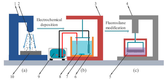
Figure 1.
Experimental process diagram (a) the sandblasting device (b) the Electrodeposition device (c) the modification device.
- Sandblasting of the surface of C45E4 by sandblasting device;
- Preparing of the Ni-Co coating on the surface after treatment by electrodeposition device;
- Modified Ni-Co coating the by modification device.
In the first step, the C45E4 substrate surface was pretreated. Step one 1. used 800 # and 1500 # water sandpaper for polishing pretreatment. 2. The sand blasting pretreatment is shown in Figure 1a, which fixed the C45E4 substrate (10) in the sandblasting device (1); then gravel (2) was pushed and impacted on the substrate surface by a high-speed airflow, and the rough structure was generated by rapid erosion. The gas pressure at the nozzle outlet of the sandblasting device was 0.7 MPa, the C45E4 substrate was placed 15 cm away from the nozzle, the angle was 90 degrees, and the sandblasting time was 20 s. After pretreatment, the sample was placed in acetone, ethanol, and deionized water for ultrasonic cleaning for 5 min, and then air-dried. Finally, the sample was treated with electric deoiling, weak activation, and strong activation. After each step, the samples were rinsed with deionized water.
The second step, the sample was electrodeposited as shown in Figure 1b. The C45E4 substrate was connected to the negative electrode of the power supply (9), and the pure nickel plate (8) was connected to the positive electrode of the power supply. The two were placed in parallel in the Electrodeposition device (3). The Ni-Co bath (6) temperature was kept at 60 °C, and the magnetic rotor (7) speed was set at 800 RPM. The electrodeposition time was 90 min. After electrodeposition, the sample was cleaned by ultrasonic wave for 5 min and blow-dried.
In the third step, the Ni-Co coating was modified to reduce the surface energy. The modification device (4) is shown in Figure 1c. The fluorosilane ethanol solution was stirred magnetically for 6 h at room temperature, and then allowed to stand for 12 h before use. During the modification, the sample was immersed in the surface modification (5) solution for 2 h without stirring. Finally, the modified sample was dried at 120 °C for 1 h and sealed with an airtight plastic bag.
In this study, the samples under different preparation processes are expressed as follows: P polishing, S sandblasting, E electrodeposited Ni-Co coating, F fluorosilane ethanol solution modification, PE polishing-electrodeposited Ni-Co coating, SE sandblasting-electrodeposited Ni-Co coating, PEF polishing-electrodeposited Ni-Co coating-fluorosilane ethanol solution modification, SEF sandblasting-electrodeposited Ni-Co coating-fluorosilane ethanol solution modification.
2.3. Instruments and Characterization
A Quanta FEG 250 Field Emission Scanning Electron Microscope (FE-SEM) from FEI Instruments Inc. (Hillsboro, OR, USA) was used to investigate the surface morphology. A laser scanning confocal microscope (LSCM, OLS4000, OLYMPUS, Tokyo, Japan) was used to characterize the three-dimensional surface contour. The microstructure was characterized by a X’Pert 3 Powder X-ray Diffractometer–Spectrometer (Bragg-Brentano geometry, 0.15418 nm) (PANalytical X-ray Diffractometer Model X’pert Powder; PANalytical Inc., Almelo, Holland). The surface chemical composition was characterized by energy dispersion spectroscopy (XFlash Detector 5030; BrukerAXS, Inc., Berlin, Germany). The contact angle was measured by optical contact angle measurements (OCA15EC, Dataphysics, Munich, Germany). The volume of the water droplet was 3 μL. Electrochemical corrosion test was performed by a CS350 electrochemical workstation (Wuhan Corrtest Instruments, Wuhan, China). The test method used 3.5% NaCl solution as the corrosion medium, with the scanning range of −1 V to 1.5 V and the scanning rate of 0.5 mV·s−1. The workpiece, Pt plate, and SCE electrode were used as the working electrode, auxiliary electrode, and reference electrode, respectively. The corrosion resistance was analyzed by measuring the polarization curve and ac impedance spectrum of the sample.
3. Results and Discussion
3.1. Surface Morphology
The surface microstructure and morphology of the samples with different preparation processes was as shown in Figure 2. It can be seen that the surface was flat and smooth without scratches in Figure 2a. Figure 2b shows that the surface was rough, with many irregular pits, furrows, and flaky projections (regions B1 and B2 in Figure 2b). The flaky protrusions between the pits were in the shape of mountain clusters. The rough structure could be constructed on the surface of the substrate quickly by sandblasting. The surface was covered with dense particles of different sizes, the dense particles were of flat distribution on the whole, and there was no protruding cellular structure in Figure 2c. It shows that the concentration of the plating solution could be uniform through magnetic rotor stirring during electrodeposition. At high magnification, the particles distributed on the surface of the sample were clusters of flowers (region C in Figure 2c). The structure was formed by the co-deposition of Ni and Co atoms in the plating solution after Ni2+ and Co2+ obtained electrons. The clusters of flowers were distributed densely and flatly, forming a mastoid morphology close to the surface of lotus leaves, which reduces the contact area between droplets and the coating surface. Compared with the PE sample, there was a cellular protuberant structure on the surface (region D in Figure 2d). This is due to the existence of pits and lamellar protrusions on the surface of sample S, which increased the total surface area, so that the number of petal clusters deposited on the surface increased under the same electrodeposition conditions, and the shape of agglomeration increased. The contact form between the cell and droplet was more diverse and complex, and the contact area was less than that of the flat surface. After being modified by fluorosilane ethanol solution, a layer of film was formed on the surface, which is composed of uniformly distributed pinecone projections (region E in Figure 2e). According to the bionics principle, this structure was similar to the mastoid structure on the superhydrophobic surface of the lotus leaf. When the surface was in contact with the droplet, only the tip of the mastoid process was in contact with the droplet interface. The gap between the mastoid process was small, making it difficult for the droplet to enter. The surface can achieve the effect of hydrophobicity. Compared with the surface of the PEF sample, the presence of surface cellular projections of the SEF sample increased the pinecone projections, forming agglomeration in the cell (region F in Figure 2f). The distribution of the mastoid structure was denser, which further enhanced the surface hydrophobic performance, reaching the state of superhydrophobic. The upper right of Figure 2e,f show the surface distribution of element F which was measured by EDS, proving the presence of fluorosilane uniformly deposited on the coating surface.
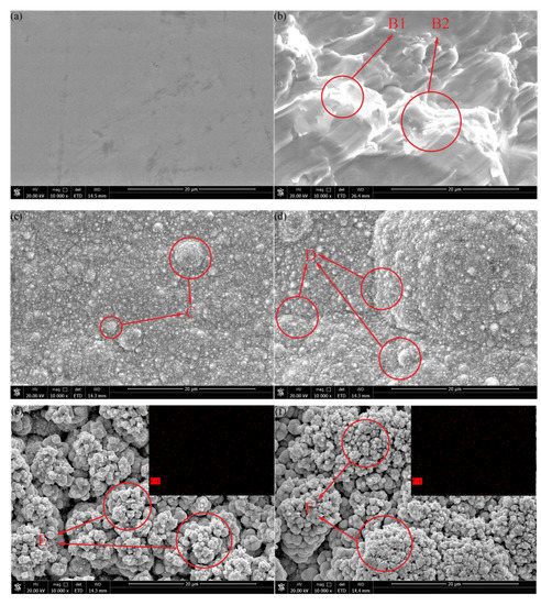
Figure 2.
Surface microstructure and morphology of the samples with different preparation processes: (a) polishing (P) (b) sandblasting (S) (c) polishing-electrodeposited Ni-Co coating (PE) (d) sandblasting-electrodeposited Ni-Co coating (SE) (e) polishing-electrodeposited Ni-Co coating-fluorosilane ethanol solution modification (PEF) (f) sandblasting-electrodeposited Ni-Co coating-fluorosilane ethanol solution modification (SEF).
By analyzing the surface morphology of samples under different preparation processes, sandblasting pretreatment can construct a micron rough structure on the surface. Electrodeposited Ni-Co coating can be used to construct a fine flower-cluster rough structure on the surface of the C45E4 substrate. The structure of pinecone mastoid could be deposited on the surface by fluorosilane ethanol solution modification. According to the principle of bionics, this structure can effectively reduce the contact area between the surface and the liquid droplets, and the number of such structures can be increased after sandblasting pretreatment to further improve the surface hydrophobic performance.
3.2. Surface Roughness
The surface roughness of the three-dimensional morphology of the samples with different preparation processes is shown in Figure 3. The results of measuring surface roughness (evaluation standard: 100 μm × 100 μm × 100 μm) are shown in Table 2, Sa (arithmetical mean height) is the square-root roughness. The roughness of the surface of the P sample Sa is 0.006. The surface is flat in Figure 3a. The surface of S sample morphology was rough and the size and shape of the protruding structure and pits were different which makes the Sa increase to 0.804 in Figure 3b. The three-dimensional morphology of the PE sample is shown in Figure 3c. The flower cluster structure formed after electrodeposition of the Ni-Co coating made the surface rough, but the roughness was low, and the overall surface was flat without protrusions. The measured Sa of the sample is 0.091, which is higher than the polished plane, indicating that electrodeposition can increase surface roughness. The three-dimensional morphology of the SE sample is shown in Figure 3d. Compared with the PE sample, the Sa of the sample increases to 0.901, and the surface showed an obvious rough appearance. After electrodeposition of the Ni-Co coating, the surface protruding structure was obvious, which effectively reduces the surface contact area with liquid drops. The three-dimensional morphology of the PEF sample is shown in Figure 3e. After the modification of fluorosilane, the Sa of the sample increases to 0.192. This is because the pinecone shape attached to the surface further refined the surface rough structure, and the mastoid structure was densely distributed. Compared with PE, the roughness of the surface is increased, which enhances the hydrophobic performance of the surface. The three-dimensional morphology of the SEF sample is shown in Figure 3f. Compared with the PEF sample, the surface protrusions were obvious, and the structure morphology was more diversified. The Sa is 1.307, indicating the highest roughness among the six samples. SEF samples have the roughest surface structure, more diverse contact forms with liquid droplets, and the best hydrophobic performance.
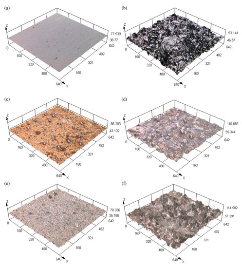
Figure 3.
Surface roughness of the three-dimensional morphology of the samples with different preparation processes. (a) P; (b) S; (c) PE; (d) SE; (e) PEF; (f) SEF.

Table 2.
Surface roughness Sa of samples with different preparation processes.
Studies have shown that with the increase in surface roughness, the spread rate of droplets on the surface will gradually decrease [22]. The contact diffusion form between surface roughness and the droplet is shown in Figure 4a is a smooth plane, Figure 4b is a slightly rough plane, and Figure 4c is a highly rough plane. When the droplet is in contact with the smooth surface, it will spread rapidly because there is no resistance. On contact with a rough surface, the air between the pits prevents the droplets from diffusing. The more pits there are, the more air will be stored and the stronger the film of air will be in preventing the droplets from diffusing. At the same time, the solid–liquid contact area S1 > S2 > S3 was formed by diffusion. Sandblasting pretreatment could quickly construct a rough structure on the substrate surface, the Sa of sample S is higher than that of sample P, so the diffusion area of the sandblast surface is smaller. After electrodeposition of Ni-Co coating, fine and rough structure would store air effectively. Due to protrusions and pits on the surface of the SE sample, more air would be stored than that of the PE sample, thus reducing the diffusion area. After the treatment of the fluorosilane ethanol solution, the rough structure of the surface was further refined. Compared with the PEF sample, the diffusion area is smaller and the hydrophobic performance is the best.
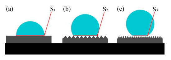
Figure 4.
Contact diffusion form between surface roughness and droplet (a) smooth plane (b) slightly rough plane (c) highly rough plane.
By analyzing the three-dimensional morphology of the samples with different preparation processes, the electrodeposited Ni-Co coating can increase the surface roughness, which can be further increased after modification. The surface roughness of the C45E4 substrate is much larger than that of the polished sample after sandblasting pretreatment. The increase in surface roughness can reduce the diffusion of droplets on the surface, which is conducive to the improvement of surface hydrophobic performance.
3.3. XRD Analysis
The XRD patterns of the Ni-Co coating samples is presented in Figure 5. The diffraction pattern is similar to that of pure Ni, and the three diffraction peaks in the spectrum correspond to the diffraction peaks of the Ni (111), Ni (200), and Ni (220) crystal planes of the Ni crystals. All the surfaces show a face-centered cubic structure. The preferred growth orientation of the crystal surface is (111). No peak corresponding to Co is found in the diffraction pattern. This is because the atoms of Ni and Co are similar in size. The partial lattice of Ni atoms is replaced by Co atoms in the form of a substitute solution to form a single-phase Ni-Co solid solution. In the XRD pattern of the superhydrophobic surface of the SEF sample, the peak of fluorosilane ethanol solution cannot be found. This is because only a small amount of fluorosilane ethanol solution is adsorbed on the surface of the Ni-Co coating during the modification process. The diffraction peaks of the PE and the SE samples in the growth direction of (111) crystal plane were 44.497°and 44.405°, respectively. The diffraction peaks of PEF and SEF samples in the growth direction of (111) crystal plane were 44.349° and 44.494°, respectively. The diffraction peaks are shifted to the right by 0.108° and 0.145°, respectively. The results showed that the lattice distortion occurred in the formation of the matrix surface after sandblasting pretreatment, and the surface microstructure became denser, to improve the hydrophobicity and corrosion resistance of the surface [7].
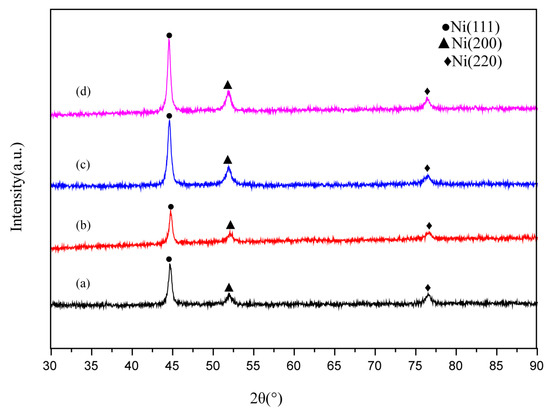
Figure 5.
XRD patterns of the surface of samples with different preparation processes (a) PE; (b) SE; (c) PEF; (d) SEF.
3.4. Wettability and Stability
The surface contact angle (CA value) to characterize the wettability of the sample surface is shown in Figure 6. The CA value of sample P is 88.1° (Figure 6a-1), and it is hydrophilic. This is because the polished surface was smooth and the water droplets spread rapidly under the action of gravity. The CA value of sample S is 130.5° (Figure 6b-1), and the hydrophobic performance is significantly improved. After sandblast treatment, the surface had many different shapes of bumps and pits, which increase the rough morphology of the sample surface and make the surface show good hydrophobic performance. The CA value of the PE sample is 134.9° (Figure 6c-1), indicating that the petal-like tufted structure formed by electrodeposition of Ni-Co coating makes the surface have good hydrophobicity. The CA value of the SE sample is 140.3° (Figure 6d-1). The protrusions and pits on the sandblasting surface would increase the number of petals deposited in clusters, and the contact forms with droplets were diverse and complex, which are more hydrophobic than PE samples. The CA value of the PEF sample is 148.5 ° (Figure 6e-1), indicating that the coating has a very high hydrophobic performance after being modified by a fluorosilane ethanol solution. The mastoid structure deposited on the surface can effectively prevent contact with droplets, which is close to superhydrophobic. The CA value of the SEF sample is 151.2° (Figure 6f-1), showing a superhydrophobic state. The number of mastoid structures increased after sandblasting pretreatment, and the agglomeration of the protrusions could further prevent the droplets from entering the coating and effectively protected the substrate material.

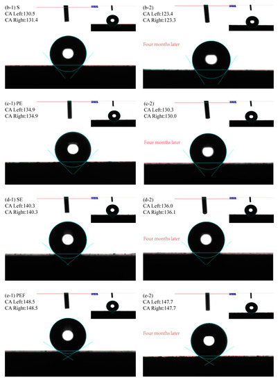
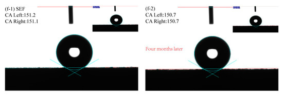
Figure 6.
The contact angles of samples with different preparation processes (a-1) P; (b-1) S; (c-1) PE; (d-1) SE; (e-1) PEF; (f-1) SEF; (a-2) P(Four months later); (b-2) S(Four months later); (c-2) PE(Four months later); (d-2) SE(Four months later); (e-2) PEF(Four months later); (f-2) SEF(Four months later).
To analyze the hydrophobic stability of the sample surface, the sample was exposed to air for four months and the CA values were measured again. It is found that the CA values on the surface of P and S samples are significantly reduced. This is because the surface will be eroded by moisture when it is left in the air for a long time. The formation of rust would damage the surface structure. The CA values on the surface of the PE and the SE sample are slightly reduced to 130.3°and 136.0°, respectively. This is due to the moisture in the air which would adhere to the coating surface in a small amount after long exposure to air. The Ni-Co coating shows good stability. The surface of the PEF sample and the SEF sample also show good hydrophobicity, with CA values of 147.7°and 150.7°, respectively. After the surface was modified, it remains stable in the air, while the surface of the SEF sample still shows superhydrophobicity.
This phenomenon can be explained by the Cassie–Baxter equation, as shown in Equation (1) [12].
where f1 and f2 are fractional areas of the solid and air on the surface, respectively (i.e. f1 + f2 = 1); θr and θ are water contact angles on rough and smooth solid surfaces, respectively. When the rough structure occurs on the surface of the sample, the droplet on the surface can store air between the rough structure to form a backpressure film, reducing the contact area f1 between the droplet and the surface. The rough structure enhances the hydrophobicity of the surface and obtains a higher contact angle, reaching the state of superhydrophobicity finally. Taking the polished surface as a reference, the calculated solid–liquid contact area ratio and droplet volume vacancy of the samples of different preparation processes are shown, Table 3. SEF is only equivalent to 12% of the contact area between the P sample and water droplets, and about 88% of the droplets are in contact with air, showing excellent superhydrophobicity.
Cos θr = f1 cosθ − f2

Table 3.
Solid–liquid contact area ratio f.
Studies have shown that there is a synergistic effect between the corrosion resistance of the material and the wettability of the surface [33,34,35]. The hydrophobic surface can store air and form a thin film of air, preventing the erosion of the corrosive medium in the water. The larger the water contact angle, the stronger the resistance and the better the corrosion resistance of the surface.
3.5. Corrosion Resistance
To study the corrosion resistance of the superhydrophobic Ni-Co coating, the sample was immersed in 3.5 wt % NaCl neutral aqueous solution. The exposed area of the sample was 1 cm2, and the dynamic potential polarization (Tafel) curve and ac impedance spectroscopy (EIS) curves were measured. The polarization curve is shown in Figure 7. By Tafel extrapolation of the polarization curve, we calculated the self-etching potential (Ecorr), self-etching current density (Icorr), and corrosion rate of each electrochemical parameter by fitting, as listed in Table 4. Compared with polished samples, the corrosion potential increased from −1.13 V to −0.91 V after sandblasting pretreatment, and the corrosion current density decreased from 46.717 × 10⁻⁵ A·cm−2 to 2.1472 × 10⁻⁵ A·cm−2, indicating that the corrosion resistance of the surface was significantly improved. PE compared with P and SE compared with S, the corrosion potential increased significantly. It is shown that the Ni-Co coating can provide effective protection against corrosion to the exposed substrate. When the surface was treated with fluorosilane ethanol, the corrosion potential further increased, and the corrosion current density further decreased. The corrosion potential on the superhydrophobic surface of the SEF sample was the highest, which was −0.33 V, and the corrosion current density was the lowest, which was 5.0519 × 10⁻⁷ A·cm−2. The corrosion rate was about 0.103% of that of the P sample and 42.042% of that of the PEF sample. Sandblasting pretreatment can provide better corrosion protection than polishing pretreatment. Equation (2) from [35] was used to calculate the corrosion inhibition rate of the superhydrophobic surface,
where IPEF, and ISEF are the corrosion current density of the PEF sample and the SEF sample, respectively. It was calculated that under the same deposition and modification conditions, the inhibition rate of IE on the surface of SEF samples was 53.33% of that of the PEF sample. The superhydrophobic surface has excellent corrosion resistance because of its strong ability to absorb air. A large area of air film is formed on the surface to isolate water, thus effectively preventing the surface from contacting with chloride ions in an aqueous solution of 3.5 wt % NaCl. In the previous analysis, the flower cluster structure generated by electrodeposition of Ni-Co coating can initially form an air film. A large number of pinecone mastoid structures were deposited on the surface after the modification of fluorosilane ethanol solution, which thickens the air film. Sandblasting treatment enables the surface to absorb and store more air, with excellent hydrophobic performance and corrosion resistance.
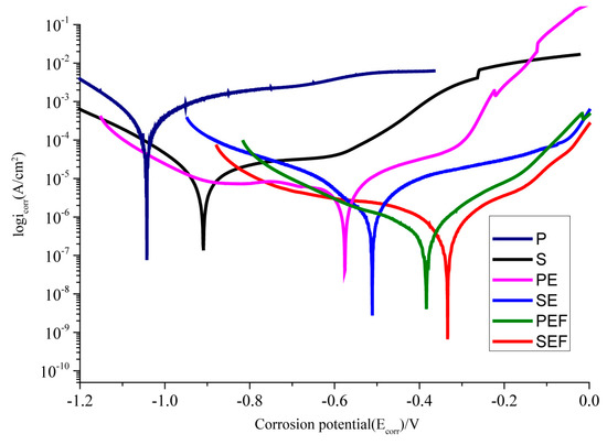
Figure 7.
Polarization curves of samples with different preparation processes.

Table 4.
Polarization curve parameters of samples with different preparation processes.
In order to study the corrosion resistance of the superhydrophobic Ni-Co coating, the corrosion behavior of each sample in 3.5 wt % NaCl solution was measured by the alternating current impedance (EIS) method. The Nyquist plots of the measured ac-impedance spectra of the samples are plotted as shown in Figure 8. The diameter of the capacitance circuit represents the impedance of the working electrode. We can see that the impedance value of sample S is greater than that of sample P, and the impedance value of sample SEF is the largest with the best corrosion resistance, which is consistent with the results of the polarization curve and parameters in Figure 7 and Table 4. For the quantitative analysis of sample corrosiveness, the corresponding EIS equivalent circuit diagram model is proposed in Figure 9. The results fitted are by ZsimpWin software, Table 5. Where R1 represents NaCl solution equivalent electrolyte resistance, R2 is the polishing matrix equivalent resistance, R3 is the enhanced equivalent resistance after sandblasting, R4 is the Ni-Co coating equivalent resistance, and R5 is the equivalent resistance of fluorosilane ethanol solution medium. A constant phase element (CPE) is used to replace the capacitor in the equivalent circuit to more accurately fit the impedance characteristics of the double layer. The Sandblasting pretreatment process can improve the impedance value of the substrate; the impedance value moves from 331.6 Ω to 1.36 × 10⁴ Ω. Electrodeposition of Ni-Co coating and modification of fluorosilane can improve the equivalent resistance. The equivalent resistance value of sandblasted samples is higher than that of polished samples under the same process. SEF sample equivalent resistance value is 1.74 × 10⁸ Ω, which is the highest of all. The Superhydrophobic surface can improve the corrosion resistance of the C45E4 substrate.
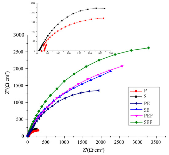
Figure 8.
Impedance spectra of samples with different preparation processes.
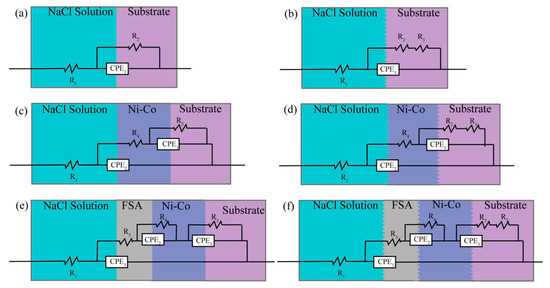
Figure 9.
Equivalent circuit diagram of different preparation processes (a) P; (b) S; (c) PE; (d) SE; (e) PEF; (f) SEF.

Table 5.
Equivalent circuit diagrams of different preparation processes.
4. Mechanism
The mechanism of Ni-Co coating deposition on the superhydrophobic surface is shown in Figure 10. Compared with the polishing pretreatment, the C45E4 substrate is sandblasted before electrodeposition of Ni-Co coating, which can make the initial surface form a micron level rough structure such as pits, furs, and flakiness, etc., and increase the surface roughness to facilitate deposition. When electrodepositing the Ni-Co coating, the Ni atoms and Co atoms are deposited together to form a flower cluster structure, and the high surface density initially forms a mastoid morphology close to the surface of the lotus leaf. A flower cluster structure can reduce the surface area of contact with the liquid in humid air and effectively prevent water erosion. After sandblasting pretreatment, the surface is rough, and the process of deposition produces cellular protuberance, which increases the number of flower clusters deposited on the surface and enriches the surface structure. After electrodeposition of the Ni-Co coating, the surface was modified with a fluorosilane ethanol solution, and the coating surface was coated with a micron particle film. This thin film microstructure is shown in the Figure 2. It consists of a large number of pinecone mastoid structures attached to the flower clusters. This structure is composed of succulent mastoid structures. According to the principle of bionics, the mastoid structure distributed on the pinecone structure is similar to the mastoid structure on the surface of the lotus leaf. When the droplet is attached to the surface, only the tip of the mastoid process contacts the droplet interface, and the gap between the mastoid process is very small, forming an air anti-pressure film to prevent the droplet from entering, and reducing the surface, which can achieve the hydrophobic effect. Sandblasting pretreatment makes the surface of the Ni-Co coating cellular protrude, which can deposit more papillae structure, and agglomeration phenomenon occurs. The contact form with liquid drops is rich and diverse, and finally, the water contact angle reaches 151.2°, forming a superhydrophobic surface.
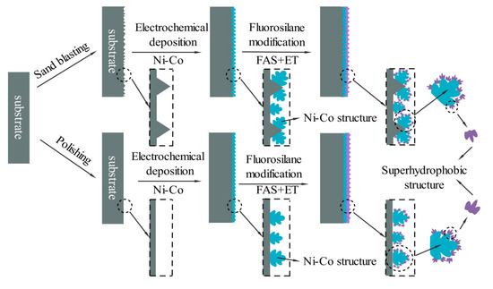
Figure 10.
Mechanism of Ni-Co coating deposition on a superhydrophobic surface.
5. Conclusions
- 1.
- By electrodeposition of an Ni-Co coating, the surface formed a flower cluster structure. By the modification with fluorosilane ethanol solution, the cone-shaped mastoid structure could be deposited on the flower cluster structure again. It was similar to the mastoid structure on the superhydrophobic surface of the lotus leaf. Sandblasting pretreatment increased the number of biomimetic structures deposited on the surface and enhanced the hydrophobic performance of the surface.
- 2.
- Electrodeposition of the Ni-Co coating increased the roughness of the C45E4 substrate surface, and the surface roughness could be further increased by modification of fluorosilane ethanol solution. Sandblasting pretreatment made the surface roughness of the SE sample much larger than that of the PE sample under the same technological conditions. The increase in surface roughness reduced the diffusion of droplets on the surface, which was conducive to the improvement of surface hydrophobic performance.
- 3.
- After electrodeposition of the Ni-Co coating and modification by fluorosilane ethanol solution, the surface of Ni-Co coating showed a face-centered cubic structure, and the preferred growth orientation of the crystal surface was (111). Sandblasting pretreatment made the diffraction peak shift to the right, the lattice distortion occurred in the formation process, and the surface structure became denser, so as to improve the surface hydrophobicity and corrosion resistance.
- 4.
- Through sandblasting pretreatment of an C45E4 substrate, the electrodeposited Ni-Co coating and the modification with fluorosilane ethanol solution made the surface contact angle reach 151.2°, forming a super-hydrophobic surface with stable long-term hydrophobicity.
- 5.
- Compared with the polished sample, the corrosion potential increased from −1.13 V to −0.91 V after sandblasting pretreatment, and the corrosion current decreased from 46.717 × 10⁻⁵ A·cm−2 to 2.1472 × 10⁻⁵ A·cm−2. The corrosion resistance was improved. The corrosion potential on the superhydrophobic surface of the SEF sample was the highest, which was −0.33 V, and the corrosion current was the lowest, which was 5.0519 × 10⁻⁷ A·cm−2. The corrosion rate was about 0.103% of that of the P sample and 42.042% of that of the PEF sample. The sandblasting pretreatment could provide better corrosion protection than the polishing pretreatment. The impedance value of the sample S was higher than that of sample P, and the resistance value of sample SEF was the highest. The superhydrophobic surface improved the corrosion resistance of the C45E4 substrate.
Author Contributions
Conceptualization, Z.S. and Z.Z.; methodology, Z.Z., X.F. and Z.S.; software, Z.S. and L.L.; validation, X.F., Z.Z. and H.W.; formal analysis, Z.Z., Z.S.; investigation, H.W., Z.S. and L.L.; resources, Z.Z.; data curation, Z.S. and X.F.; writing—original draft preparation, X.F. and Z.S.; writing—review and editing, L.L., H.W.; visualization, Z.S. and Z.Z.; supervision, X.F., Z.S. and Z.Z.; project administration, Z.Z. and X.F.; funding acquisition, Z.S., Z.Z. and X.F.; All authors have read and agreed to the published version of the manuscript.
Funding
This work was financially supported by the Fundamental Research Funds for the Central Universities (Grant number KJSY201715), the Fundamental Research Funds for the Central Universities (Grant number KYXJ202002), Jiangsu Agricultural Science and Technology Innovation Fund (Grant number CX (20) 3085).
Conflicts of Interest
The authors declare no conflict of interest.
References
- Wang, L.P.; Zhuang, L.; Chen, G.; Leng, D.; Wang, J.; Cheng, L.; Wei, L.; Wang, J.B.; Hou, B.R. Superhydrophobic Surface Fabricated on Carbon Steel Substrate by Zinc Electrodeposition for Prevention of Corrosion. In Proceedings of the 2018 4th International Conference on Energy Materials and Environment Engineering (ICEMEE 2018), Kuala Lumpur, Malaysia, 13–15 April 2018; Mostafa, M., Ed.; EDP Sciences: Les Ulis, France, 2018; Volume 38. [Google Scholar] [CrossRef]
- Leoni, G.B.; de Freitas, D.S.; Ponciano Gomes, J.A.C.; Brasil, S.L.D.C. Multivariable analysis of electrodeposited silane based superhydrophobic coatings for corrosion protection of carbon steel. J. Sol-Gel Sci. Technol. 2020, 94, 695–707. [Google Scholar] [CrossRef]
- Xue, Y.P.; Wang, S.Q.; Peng, B.; Zhao, G.C.; Jin, Y. Super-Hydrophobic Co–Ni Coating with High Abrasion Resistance Prepared by Electrodeposition. Coatings 2019, 9, 232. [Google Scholar] [CrossRef]
- Xu, M.Y.; Shen, L.D.; Jiang, W.; Qiu, M.B.; Tian, Z.J. Study on the properties of superhydrophobic nickel coating prepared by jet electrodeposition in a parallel magnetic field. Mater. Res. Express 2019, 6, 086462. [Google Scholar] [CrossRef]
- Hashemzadeh, M.; Raeissi, K.; Ashrafizadeh, F.; Khorsand, S. Effect of ammonium chloride on microstructure, super-hydrophobicity and corrosion resistance of nickel coatings. Surf. Coat. Technol. 2015, 283, 318–328. [Google Scholar] [CrossRef]
- He, Y.; Sun, W.T.; Wang, S.C.; Reed, P.A.S.; Walsh, F.C. An electrodeposited Ni-P-WS2 coating with combined super-hydrophobicity and self-lubricating properties. Electrochim. Acta 2019, 245, 872–882. [Google Scholar] [CrossRef]
- Karimzadeh, A.; Aliofkhazraei, M.; Walsh, F.C. A review of electrodeposited Ni-Co alloy and composite coatings: Microstructure, properties and applications. Surf. Coat. Technol. 2019, 372, 463–498. [Google Scholar] [CrossRef]
- Darband, G.B.; Aliofkhazraei, M.; Khorsand, S.; Sokhanvar, S.; Kaboli, A. Science and Engineering of Superhydrophobic Surfaces: Review of Corrosion Resistance, Chemical and Mechanical Stability. Arab. J. Chem. 2020, 13, 1763–1802. [Google Scholar] [CrossRef]
- Xu, S.S.; Wang, Q.; Wang, N.; Zheng, X. Fabrication of superhydrophobic green surfaces with good self-cleaning, chemical stability and anti-corrosion properties. J. Mater. Sci. 2019, 54, 13006–13016. [Google Scholar] [CrossRef]
- He, G.; Lu, S.X.; Xu, W.G.; Ye, P.; Liu, G.X.; Wang, H.T.; Dai, T.L. Stable superhydrophobic Zn/ZnO surfaces fabricated via electrodeposition on tin substrate for self-cleaning behavior and switchable wettability. J. Alloys Compd. 2018, 747, 772–782. [Google Scholar] [CrossRef]
- Chen, C.L.; Fan, Y.; He, Y.; Chen, X.; Yan, Q.B. Fabrication of superhydrophobic zirconium surface with a facile electrodeposition process. Surf. Innov. 2018, 6, 106–115. [Google Scholar] [CrossRef]
- Lee, J.M.; Ko, J.S. Cu–Ni alloy electrodeposition on microstructured surfaces. J. Mater. Sci. 2014, 50, 393–402. [Google Scholar] [CrossRef]
- Wang, N.; Yuan, Y.; Wu, Y.; Hang, T.; Li, M. Wetting transition of the caterpillar-like superhydrophobic Cu/Ni-Co hierarchical structure by heat treatment. Langmuir 2015, 31, 10807–10812. [Google Scholar] [CrossRef]
- An, J.; Sun, H.; Cui, J.; Zhu, Z.; Liang, W.; Pei, C.; Yang, B.; Li, A. Surface modification of polypyrrole-coated foam for the capture of organic solvents and oils. J. Mater. Sci. 2014, 49, 4576–4582. [Google Scholar] [CrossRef]
- Sathanikan, A.; Guittard, F.; Darmanin, T. A bioinspired strategy for poly(3,4-ethylenedioxypyrrole) films with strong water adhesion. Pure Appl. Chem. 2020, 92, 315–322. [Google Scholar] [CrossRef]
- Wang, Z.D.; Kong, W.; Si, L.X.; Niu, J.; Liu, Y.; Yin, L.P.; Tian, Z.G. Robust and Thermally Stable Butterfly-Like Co (OH)(2)/Hexadecyltrimethoxysilane Superhydrophobic Mesh Filters Prepared by Electrodeposition for Highly Efficient Oil/Water Separation. Ind. Eng. Chem. Res. 2019, 58, 9576–9584. [Google Scholar] [CrossRef]
- El-Maiss, J.; Darmanin, T.; Guittard, F. Branched versus linear perfluorocarbon chains in the formation of superhydrophobic electrodeposited films with low bioaccumulative potential. J. Mater. Sci. 2014, 49, 7760–7769. [Google Scholar] [CrossRef]
- Xu, W.; Rajan, K.; Chen, X.G.; Sarkat, D.K. Facile electrodeposition of superhydrophobic aluminum stearate thin films on copper substrates for active corrosion protection. Surf. Coat. Technol. 2019, 364, 406–415. [Google Scholar] [CrossRef]
- Kundu, D.; Banerjee, D.; Ghosh, S.; Tewari, R.C.; Das, N.S.; Das, B.; Chattopadhyay, K.K. Achievement of nearly super hydrophobicity in plasma enhanced chemical vapour deposited one and two dimensional carbon nanostructures. Phys. E. Low Dimens. Syst. 2019, 108, 7–14. [Google Scholar] [CrossRef]
- Speidel, A.; Murray, J.W.; Bisterov, I.; Mitchell-Smith, J.; Parmenter, C.; Clare, A.T. Thermal Activation of Electrochemical Seed Surfaces for Selective and Tunable Hydrophobic Patterning. ACS Appl. Mater. Interfaces 2020, 12, 7744–7759. [Google Scholar] [CrossRef]
- Wen, Y.Q.; Kong, D.; Shang, W.; Ma, M.M.; Jiang, J.Q.; Li, J.P.; Peng, N. Effect of bis-(3-triethoxysilylpropyl)-tetrasulfide on Super-Hydrophobicity and Corrosion Resistance of Self-Assembled Monolayers on 6061 Aluminum Alloys. Int. J. Electrochem. Sci. 2019, 14, 6018–6031. [Google Scholar] [CrossRef]
- Zhang, Z.Y.; Gu, Q.M.; Jiang, W.; Zhu, H.; Xu, K.; Ren, Y.P.; Xu, C. Achieving of bionic super-hydrophobicity by electrodepositing nano-Ni-pyramids on the picosecond laser-ablated micro-Cu-cone surface. Surf. Coat. Technol. 2019, 363, 170–178. [Google Scholar] [CrossRef]
- Zhang, Y.; Lin, T. Influence of duty cycle on properties of the superhydrophobic coating on an anodized magnesium alloy fabricated by pulse electrodeposition. Colloids Surf. A 2019, 568, 43–50. [Google Scholar] [CrossRef]
- Jiang, S.Z.; Guo, Z.G.; Deng, Y.; Dong, H.; Li, X.Y.; Liu, J.W. Effect of pulse frequency on the one-step preparation of superhydrophobic surface by pulse electrodeposition. Appl. Surf. Sci. 2018, 458, 603–611. [Google Scholar] [CrossRef]
- Akbari, R.; Godeau, G.; Mohammadizadeh, M.R.; Guittard, F.; Darmanin, T. Fabrication of Superhydrophobic Hierarchical Surfaces by Square Pulse Electrodeposition: Copper-Based Layers on Gold/Silicon (100) Substrates. ChemPlusChem 2019, 84, 368–373. [Google Scholar] [CrossRef]
- Shen, L.D.; Fan, M.Z.; Qiu, M.B.; Jiang, W.; Wang, Z.W. Superhydrophobic nickel coating fabricated by scanning electrodeposition. Appl. Surf. Sci. 2019, 483, 706–712. [Google Scholar] [CrossRef]
- Shen, L.D.; Xu, M.Y.; Jiang, W.; Qiu, M.B.; Fan, M.Z.; Jin, G.B.; Tian, Z.J. A novel superhydrophobic Ni/Nip coating fabricated by magnetic field induced selective scanning electrodeposition. Appl. Surf. Sci. 2019, 489, 25–33. [Google Scholar] [CrossRef]
- Wang, Z.W.; Shen, L.D.; Qiu, M.B.; Jiang, W.; Chen, Y.; Zhao, J.F. Study on the properties of superhydrophobic coating prepared by scanning electrodeposition on SLM substrate. Mater. Res. Express 2019, 6, 106409. [Google Scholar] [CrossRef]
- Wang, Z.W.; Shen, L.D.; Jiang, W.; Fan, M.Z.; Liu, D.C.; Zhao, J.F. Superhydrophobic nickel coatings fabricated by scanning electrodeposition on stainless steel formed by selective laser melting. Surf. Coat. Technol. 2019, 377, 124886. [Google Scholar] [CrossRef]
- Mortier, C.; Darmanin, T.; Guittard, F. Direct Electrodeposition of Superhydrophobic and Highly Oleophobic Poly(3,4-ethylenedioxypyrrole) (PEDOP) and Poly(3,4-propylenedioxypyrrole) (PProDOP) Nanofibers. ChemNanoMat 2017, 3, 885–894. [Google Scholar] [CrossRef]
- Ifires, M.; Hadjersi, T.; Chegroune, R.; Lamrani, S.; Moulai, F.; Mebarki, M.; Manseri, A. One-step electrodeposition of superhydrophobic NiO-Co(OH)(2) urchin-like structures on Si nanowires as photocatalyst for RhB degradation under visible light. J. Alloys Compd. 2019, 774, 908–917. [Google Scholar] [CrossRef]
- Meng, J.B.; Dong, X.J.; Zhao, Y.G.; Xu, R.F.; Bai, X.; Zhou, H. Fabrication of a Low Adhesive Superhydrophobic Surface on Ti6Al4V Alloys Using TiO2/Ni Composite Electrodeposition. Micromachines 2019, 10, 121. [Google Scholar] [CrossRef]
- Li, J.; Pan, L.D.; Fu, Q.; Zhou, Y.L.; Guo, N. Wettability and corrosion behavior of a Ni coating on 304 stainless steel surface. Surf. Coat. Technol. 2019, 357, 740–747. [Google Scholar] [CrossRef]
- Yu, Z.Q.; Zhou, C.; Liu, R.; Zhang, Q.X.; Gong, J.W.; Tao, D.H.; Ji, Z.Y. Fabrication of superhydrophobic surface with enhanced corrosion resistance on H62 brass substrate. Colloids Surf. A 2020, 589, 124475. [Google Scholar] [CrossRef]
- She, Z.; Li, Q.; Wang, Z.; Tan, C.; Zhou, J.; Li, L. Highly anticorrosion, self-cleaning superhydrophobic Ni–Co surface fabricated on AZ91D magnesium alloy. Surf. Coat. Technol. 2014, 251, 7–14. [Google Scholar] [CrossRef]
- Chen, J.S.; Guo, J.; Qiu, M.B.; Yang, J.M.; Huang, D.Z.; Wang, X.L.; Ding, Y.F. Preparation of Copper-Based Superhydrophobic Surfaces by Jet-Electrodeposition. Mater. Trans. 2018, 59, 793–798. [Google Scholar]
- Jain, R.; Pitchumani, R. Facile Fabrication of Durable Copper-Based Superhydrophobic Surfaces via Electrodeposition. Langmuir 2018, 34, 3159–3169. [Google Scholar] [CrossRef]
- Zheng, T.X.; Hu, Y.B.; Pan, F.S.; Zhang, Y.X.; Tang, A.T. Fabrication of corrosion-resistant superhydrophobic coating on magnesium alloy by one-step electrodeposition method. J. Magnes. Alloys 2019, 7, 193–202. [Google Scholar] [CrossRef]
- Bahramian, A.; Eyraud, M.; Vacandio, F.; Hornebecq, V.; Djenizian, T.; Knauth, P. Single-step electrodeposition of superhydrophobic black NiO thin films. J. Appl. Electrochem. 2019, 49, 621–629. [Google Scholar] [CrossRef]
- Zhao, T.T.; Kang, Z.X.; Ma, X.Y. Fabricating Superhydrophobic Copper Meshes by One-Step Electrodeposition Method and Its Anti-Corrosion and Oil-Water Separation Abilities. Acta Metall. Sin. 2018, 54, 109–117. [Google Scholar]
- Rasitha, T.P.; Vanithakumari, S.C.; George, R.P.; Philip, J. Template-Free One-Step Electrodeposition Method for Fabrication of Robust Superhydrophobic Coating on Ferritic Steel with Self-Cleaning Ability and Superior Corrosion Resistance. Langmuir 2019, 35, 12665–12679. [Google Scholar] [CrossRef]
- Xiang, M.S.; Jiang, M.H.Z.; Zhang, Y.Z.; Liu, Y.; Shen, F.; Yang, G.; He, Y.; Wang, L.L.; Zhang, X.H.; Deng, S.H. Fabrication of a novel superhydrophobic and superoleophilic surface by one-step electrodeposition method for continuous oil/water separation. Appl. Surf. Sci. 2018, 434, 1015–1020. [Google Scholar] [CrossRef]
Publisher’s Note: MDPI stays neutral with regard to jurisdictional claims in published maps and institutional affiliations. |
© 2020 by the authors. Licensee MDPI, Basel, Switzerland. This article is an open access article distributed under the terms and conditions of the Creative Commons Attribution (CC BY) license (http://creativecommons.org/licenses/by/4.0/).