Abstract
In this study, the effects of the six technological parameters of atmospheric plasma spraying (including spraying current, spraying distance, main gas flow, auxiliary gas flow, spraying speed, and powder feeding rate) on the microhardness, density, and rate of deposition of nanoparticle cluster-oxidized yttria partially stabilized zirconia (YSZ) powder-ceramic coating were investigated through an orthogonal experiment. The structures of the powder and coating were observed by a scanning electron microscope. The hardness measurements were carried out on the samples, and the cross-section experimental results were analyzed by combining the structure of the coating and range analysis method, thereby obtaining the optimized technological parameters. The results show that the coating was primarily composed of melted ZrO2, and the coating section was a characteristic of concave–convex occlusions. Mechanical bonding played the dominant role. Main gas flow was the primary influencing parameter of performances of the atmospheric plasma spraying ZrO2 coating, followed by spraying current, auxiliary gas flow, powder feed rate, spraying speed, and spraying distance, successively. The optimal technological parameters for atmospheric plasma spraying ZrO2 coating were 75 standard cubic foot per hour (SCFH) of main gas flow, 875 A of spraying current, 45 SCFH of auxiliary gas flow, 30 g/min of powder feed rate, 400 mm/s of spraying speed, and 85 mm of spraying distance. The bonding microhardness, density, and rate of deposition of the prepared coating were HV388, 5.25 g/cm3, and 31.58%, respectively. The electrode potential and corrosion resistance of the prepared coating increased remarkably compared with that of the substrate, whereas the corrosion current decreased significantly.
1. Introduction
Magnesium alloy is an ideal and practical light structural material in high-tech fields (e.g., aviation, astronavigation, and electronics) and pillar industries (e.g., traffic transportation). It possesses potential application prospects in aerospace [1,2,3,4,5]. Magnesium alloy can be used as light shells and components of the damping system of aircrafts and spacecrafts. It can also be used to manufacture the gear case of a helicopter, accessories of a horizontal rotor wing, the landing wheel of a plane, and a gear box cover. However, the service environment becomes increasingly tough with the development of new systems. At present, although magnesium alloy is widely used as an engineering structural material because of its outstanding mechanical properties, the magnesium alloy parts easily fail because of different temperature, corrosion, and wearing resistances of substrate metals. Preparing a protective coating on the magnesium alloy surface is an effective way to prolong the service life [6,7,8]. The common surface treatment methods of magnesium alloy include micro-arc oxidation, chemical conversion, and plasma spraying. Among the methods, plasma spraying can increase surface strength and hardness simultaneously, and it is one of the research directions on the surface processing of magnesium alloy.
Studies concerning plasma spraying on magnesium alloy are limited because of two reasons. On the one hand, magnesium (Mg), which is a type of active metal, has potential safety hazards because it may generate considerable sparks upon improper control when the temperature of spraying heat source is too high. On the other hand, internal stress easily occurs in the coating because magnesium alloy has great differences in mechanical and physical properties with spraying metals or substrate metals, which are widely used in thermal spraying, thereby weakening the bonding strength between magnesium alloy and the coating. These shortages restrict the applications of plasma spraying technology in magnesium alloy industries. Feng et al. [9] prepared Al65Cu23Fe12 coatings on the AZ31 magnesium alloy surface by plasma spraying, which increased surface hardness and corrosion resistance accordingly. Ye et al. [10] prepared a Al2O3 + 3 wt.%TiO2 nano ceramic coating on the magnesium alloy surface by using the ordinary plasma spraying technology (substrate surface preprocessing–plasma spraying–thermal processing of coating), which increased surface hardness. Wang Dongsheng et al. [11] prepared Al2O3-13 wt.%TiO2 ceramic coatings by plasma spraying, which has high microhardness and good wear resistance. Daroonparvar et al. [12] sprayed triplex NiCrAlY/nano Al2O3-13 wt.%TiO2/nano TiO2 coatings on the magnesium alloy surface through atmospheric plasma spraying, which could improve corrosion resistance of magnesium alloy. Bakhsheshirad et al. [13] deposited a triple-layer NiCrAlY/nano-yttria partially stabilized zirconia (YSZ)/polycaprolactone (PCL) coating on Mg–Ca alloy by novel combination of atmospheric plasma spraying (APS) and dip coating methods, and found the corrosion resistance of Mg alloy was significantly improved. Plasma spraying can significantly increase surface hardness, wearing resistance, and corrosion resistance of alloy.
With the development of aerospace weapons, the demands for new oxidation-resisting magnesium alloy under high temperature are increasing every day. The traditional rare earth magnesium alloy, which can resist high temperatures, cannot meet the demands. Therefore, adding a thermal barrier coating is an effective way to achieve heat resistance of magnesium alloy in the future. Consequently, a layer of YSZ thermal barrier coating was prepared on the VW75 magnesium alloy surface through plasma spraying, and the rank of technical parameters that influenced the performances of the coating was obtained through an orthogonal experiment. Finally, appropriate plasma spraying parameters were optimized to prepare for follow-up services of the coating.
2. Experimental Method
2.1. Coating Materials
Mg–6.85Gd–4.52Y–1.15Nd–0.55Zr (VW75) magnesium alloy was selected as the substrate. We purify magnesium alloy melts by solvent coating and ceramic sheet filtration. The bond coat was made of NiCrAlY alloy powder which is homemade, and the relevant ingredients are listed in Table 1. The grain size d(0.5) of NiCrAlY alloy powder was 78.5 μm with a range from 50–100 μm. The morphologies of the NiCrAlY alloy powder are shown in Figure 1.

Table 1.
Chemical composition of NiCrAlY alloy powder for bond coat.
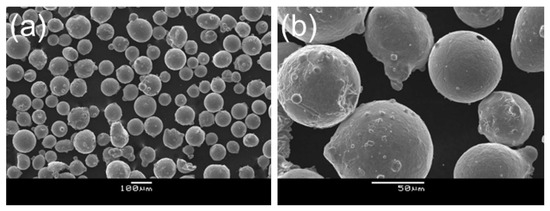
Figure 1.
Morphology of NiCrAlY alloy powder: (a) 100×; (b) 500×.
The top coat is made of nanoparticle cluster-oxidized YSZ powder which is homemade, and the ingredients are listed in Table 2. The grain size d(0.5) of the powder is 53.0 μm with a range from 30–80 μm, and its morphology is shown in Figure 2.
Table 2.
Chemical composition of nano-yttria partially stabilized zirconia (YSZ) powder as a surface material.
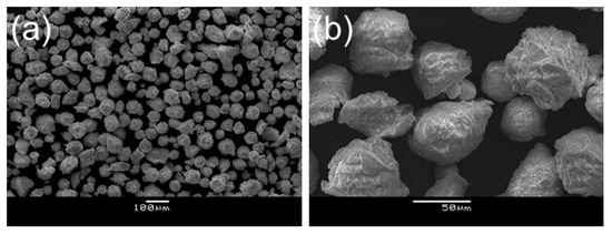
Figure 2.
Morphology of YSZ powder: (a) 100×; (b) 500×.
2.2. Preparation and Technological Process of the Coating
First, the surface of the magnesium alloy substrate was pre-processed. Abrasive blasting pre-processing was performed with an AMS9080P sand-blasting machine after oil dirt on the surface was cleaned by acetone. The surface roughness of the substrates after sand-blasting was in the range 5–7 μm. In this process, gas pressure, spraying distance, and spraying angle were set to 0.5 MPa, 50–70 mm, and 60–80°, respectively. Gravel or dust, which adhered on the coarse surface, was blown away by compressed drying gas to prevent oxidation and pollution of the rough surface after abrasive blasting. Coating should be sprayed on the samples for 3 h after abrasive blasting to increase the bonding strength between the coating and substrate. In this experiment, the 7700 plasma spraying system (Praxair Company, Danbury, CT, USA) was used, and the arm-and-hand system (ABB Company, Zurich, Switzerland) was selected as the spraying gun to control the uniformity of the coating on VW75 magnesium alloy samples.
The plasma spraying equipment has many technological parameters than can be adjusted, such as spraying current, spraying distance, main gas flow, auxiliary gas flow, spraying speed, powder feed rate, spraying voltage, diameter of the W pole, and cone angle. This experimental design excluded the technological parameters that have less effect to increase experimental efficiency. The first six parameters were used as technological factors that affect the quality of coating, which were recorded as A, B, C, D, E, and F. Each factor selected five experimental levels, which were denoted as 1, 2, 3, 4, and 5. Hence, the six-factor and five-level orthogonal experiments were constructed (Table 3).
Table 3.
Horizontal distribution table of orthogonal experimental factors of plasma spraying process parameters.
2.3. Performance Characterization
In this study, the quality of coating was assessed by microhardness and density, whereas the rate of deposition was used as the reference to the technological parameters of the coating. The comprehensive evaluation results of microhardness, density, and rate of deposition were used as the comprehensive evaluation of the coating. The microhardness of the coating was tested on the ground and polished section by using a FUTURE-TECH FM-700 microhardness meter (Future-Tech Company, Tokyo, Japan) in accordance with chinese national standard (GB) 9790-1988 [14] under 25 g of head load and 15 s of loading time. The mean of the five microhardness testing results was calculated. The density was measured using the drainage method by coating Vaseline onto the coating surface. The electrochemical results were collected by PARSTAT4000A using a classical three-electrode cell. The VW75 magnesium alloys served as the working electrode, the platinum foil was the counter electrode, and the saturated calomel electrode (SCE) was the reference electrode. The anodic materials with an area of 1 cm−2, was tested at room temperature (298 K). The electrochemical impedance spectra (EIS) were measured with the steady value of open circuit potential (OCP). The scanned frequency range was 100 kHz to 100 mHz and the voltage amplitude was 5 mV. The Tafel curves were obtained with a scan rate of 1 mV·s−1 from cathodic potentials to anodic potentials. The slope of the Tafel lines was determined by strong polarization region of Tafel curve. To ensure repeatability, at least five replicates were carried out for each test. The obtained EIS curves were fitted using ZSimpView 3.60 software.
X-ray diffraction (XRD) was obtained by a polycrystal diffractometer (PANalytical Company, Almelo, The Netherland). Cu-Kα radiation was used for the X-ray source at 40 kV, λ = 0.154 nm and 40 mA. All scans were performed from 10°–90° (2θ) at a speed of 2°/min. The rate of deposition was tested by mass measurement, and its calculation formula was as follows: Γ = , where M1 is the mass of the substrate before coating; M2 is the mass of the sample after coating, and M is the cumulative powder consumption during spraying. M1 and M2 were measured by an electronic balance with a precision of 0.01 g.
3. Research Results and Analysis
The orthogonal experimental results of microhardness, rate of deposition, and density of the coating under different factor levels are shown in Table 4.
Table 4.
L25 (56) orthogonal experiment table with six factors and five levels.
The calculated results of level “1”, level “2”, level “3”, level “4”, and level “5” of the jth factor (j represents A–F) were expressed by Ij, IIj, IIIj, IVj and Vj, respectively. The means of Ij, IIj, IIIj, IVj, and Vj indicated the five effects of the corresponding levels of the jth factor and independent effect of each level of the other five factors except for the jth factor. For example, the mean IA indicates the five effects of level “1” of factor A and the independent effect of each level (1–5) of factors B, C, D, E, and F. Therefore, the differences among mean Ij, mean IIj, mean IIIj, mean IVj, and mean Vj can be viewed as the result of the five levels of the jth factor, and they generally indicate the influences of the five levels of the jth factor on indexes.
Range analysis data about the effects of single factor on density are listed in Table 5. According to the range (Rj) data in Table 5, the sequence of Rj is RC > RA > RF > RB > RD > RE. The high value of Rj indicates the strong effects of the factor on density. Therefore, C (main gas flow) is the main influencing factor of density, followed by A (spraying current), F (powder feed rate), and B (spraying distance), successively. However, D (auxiliary gas flow) and E (spraying speed) slightly affect the density. The corresponding optimal combination of the technological parameters is A4B2C2D4E1F5.
Table 5.
Data table of density range analysis (density/g/cm3).
The microhardness range analysis data are shown in Table 6. According to the range (Rj) data in Table 6, the sequence of Rj is RC > RA > RE > RD > RF > RB. Therefore, C (main gas flow) is the main influencing factor of density, followed by A (spraying current), E (spraying speed), D (auxiliary gas flow), successively. However, F (powder feed rate) and B (spraying distance) slightly affect the density. The corresponding optimal combination of technological parameters is A4B3C2D3E3F3.
Table 6.
Microhardness Range Analysis Data Sheet (Microhardness/HV).
The range analysis results of the rate of deposition are shown in Table 7. The sequence of Rj is RF > RA > RD > RB > RC > RE. Therefore, F (powder feed rate) is the primary influencing factor of the rate of deposition, followed by A (spraying current) and D (auxiliary gas flow), successively. B (spraying distance), C (main gas flow), and E (spraying speed) slightly affect the rate of deposition. The corresponding optimal combination of the technological parameters is A4B4C3D1E3F3.
Table 7.
Data table of deposition efficiency range analysis (deposition efficiency/%).
With regard to the single index, the high hardness of materials is accompanied with high density of the coating. Higher rate of deposition of the powder is preferable. However, contradictions among different indexes are found in the multi-index experimental design. In this experiment, comprehensive performances of the coating were analyzed by weighted comprehensive scores. Considering that density, microhardness, and rate of deposition influenced the experimental results to different degrees, their weights (Wi) to the experimental objective were given according to practice experiences and analysis. In particular, the weights of density, microhardness, and rate of deposition were W1 = 0.4, W2 = 0.4, and W3 = 0.2, respectively. The sum of the weights of density, microhardness, and rate of deposition was 1.
The weighted sums of each experimental scheme were calculated. The comprehensive evaluations are shown in Table 8. As shown in Table 8, the sequence of Rj is RC > RA > RE > RF > RD > RB. Therefore, C (main gas flow) is the primary influencing factor of the comprehensive scores, followed by A (spraying current), E (spraying speed), and F (powder feed rate), successively. D (auxiliary gas flow) and B (spraying distance) slightly affect the comprehensive score. Therefore, the optimal combination of the technological parameters is A4B3C2D3E3F3. This result indicates the following spraying parameters: 875 A of spraying current, 85 mm of spraying distance, 75 SCHF of main gas flow, 45 SCFH of auxiliary gas flow, 400 mm/s of spraying speed, and 30 g/min of powder feed rate.
Table 8.
Data table of comprehensive score range analysis.
Based on the above-mentioned analysis, the main gas flow is the primary influencing factor of the comprehensive performances of plasma spraying YSZ, including the density, microhardness, and rate of deposition. Considering that the main gas flow influences the enthalpy and flow rate of plasma flame flow, and it can influence the working efficiency of spraying and the density of coating, its effect on the quality of coating cannot be ignored. When the main gas flow is too high, the melted particle concentration decreases, and considerable heat is carried away by plasma flame flow. Temperature drops, and enthalpy decreases, finally leading to the uneven and incomplete melting of powder. Consequently, the working efficiency of spraying decreases, and the coating has loose and low-density structures. On the contrary, the working pressure of the plasma gun and deflection of the plasma flame flow drop when the main gas flow is too small, which causes ablation of the nozzle. Spraying current determines the enthalpy value of the plasma arc. Excessive spraying current can cause gasification and oxidization of spraying powder, particularly in spraying powder with a low melting point. Hence, the temperature on the magnesium alloy substrate increases, which may cause burn damages to the nozzle of the plasma gun. Inadequate spraying current may lead to unstable combustion of the plasma arc, and spraying fluctuates significantly, resulting in the uneven and incomplete melting of spraying powder. Hence, the interlayer bonding of the coating is poor, whereas the bonding strength between the coating and magnesium alloy substrate decreases significantly. Spraying speed refers to the transverse swing speed of the plasma gun on the magnesium alloy surface. Considering that magnesium alloy has a low melting point, the swing speed is too low. This effect not only makes the magnesium alloy substrate too hot, but also causes the stacking of melted particles. However, the magnesium alloy substrate may obtain inadequate heat when the swing speed of the plasma gun is too high, which leads to the low bonding strength between the coating and substrate. The powder feed rate determines the molding quality of coating. The working efficiency of spraying declines significantly when the powder feed rate is too small, but uneven melting of YZS composite powder or increased number of unmelted particles can easily occur when the powder feed rate is too high, finally decreasing the density of the coating. Moreover, the enthalpy value of plasma flame flow is decreased, so that powder is heated unevenly or has inadequate heat supply. Hence, the quality of coating is difficult to guarantee. Auxiliary gas flow changes within a small range, and it lightly influences the whole spraying process. In this experiment, the applied plasma spraying device has low voltage and high current. When the spraying current is selected, the adjustment range of voltage is small. Considering that the auxiliary gas flow primarily determines the spraying voltage, it can slightly influence the spraying quality. Spraying distance determines the flying distance of melted particles and the flying time of melted particles in gas. Long spraying distance may cause two situations. On the one hand, melted particles may be frozen because of the temperature drop before arriving at the surface of the magnesium alloy substrate. On the other hand, melted particles have significantly inadequate kinetic energy to impact on the substrate surface because the spraying speed has been declined dramatically when they are approaching the substrate surface, thereby resulting in the low bonding strength between the coating and substrate. Some powder particles may be unmelted, whereas the magnesium alloy substrate is melted, oxidized, or burned when the spraying distance is too short.
Spraying current, spraying distance, main gas flow, auxiliary gas flow, spraying speed, and powder feed rate are optimized to 875 A, 85 mm, 75 CHF, 45 SCFH, 400 mm/s, and 30 g/min to guarantee the high density, microhardness, and rate of deposition of the coating. The corresponding microhardness (HV), density, and rate of deposition are 388, 5.25 g/cm3, and 31.58%, respectively.
The microstructure and XRD spectrum after plasma spraying under the optimal conditions are shown in Figure 3. The interface after plasma spraying is divided into three typical layers, which are the substrate layer, bond coat, and ceramic layer. No evident thermally grown oxide (TGO) layer is found. Except for the bond coat, the rare earth element Y has even distributions on the ceramic layer and substrate, without evident segregation. Some pores are found in the ceramic layer, indicating that achieving complete densification of the coating even under the optimal technological conditions is feasible. Based on the XRD results, the coating is all composed of tetragonal ZrO2(ICDD: 050-1089), and no other special compounds are found.
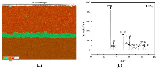
Figure 3.
Morphology and XRD results of plasma spraying coating. (a) Morphology; (b) XRD results.
The Tafel curves before and after plasma spraying on VW75 magnesium alloy are shown in Figure 4. The negative polarity regions of curves under these two states have similar shapes, but the positive polarity curve of VW75 after plasma spraying is passivated significantly, accompanied with an increase in the overall electrode potentials and a sharp reduction in the corrosion current. The lowest self-corrosion potential of the VW75 magnesium alloy substrate is only −1.7351 V, and the highest self-corrosion current density is 5.04 × 10⁻⁴A/cm2. The self-corrosion potential and self-corrosion current density of the ceramic layer are −1.1343 V and 9.55 × 10⁻⁵ A/cm2, respectively. Therefore, the self-corrosion potential of the ceramic layer sample is increased by 601 mV, but the self-corrosion current is dropped by one order of magnitude. Although a small difference is found on the slope of negative polarity curves before and after plasma spraying, the slope of the positive polarity curve after plasma spraying is increased by nearly two orders of magnitude compared with that of the substrate. This result indicates that under the same apparent current density, the electrochemical process of VW75 after plasma spraying requires high overpotential, which conforms to the analysis results of polarization resistance of the ceramic layer. Hence, the ceramic layer effectively decelerates the corrosion of samples and provides an effective protection to magnesium alloy.
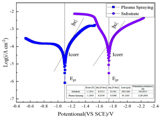
Figure 4.
Tafel curves of the substrate and ceramic layer of VW75 magnesium alloy.
The alternative current impedance spectrum of the testing coating in 3.5 wt.% of NaCl solution is shown in Figure 5. The impedance curve of the VW75 substrate is composed of a high-frequency capacitive reactance arc and a low-frequency capacitive reactance arc. Meanwhile, an equivalent circuit of the physical model was constructed (Figure 6). Rs and Rt are the solution resistance and charge transfer resistance. Qdl is a two-layer capacitor. Y0 and n are the two parameters that describe the functions of the capacitor. In the second capacitance loop, Rf and Cf are the film resistances, which are corresponding to the ceramic layer and bond coat, respectively. According to the Table 9, the circuit is proven highly reliable by a χ2 significance test.
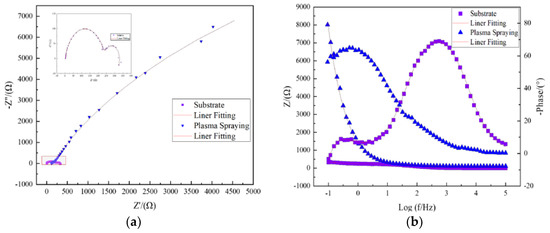
Figure 5.
Alternative current impedance spectra and bode diagrams of the VW75 substrate and plasma spraying ceramic layer. (a) Nyquist plots; (b) Bode plots.
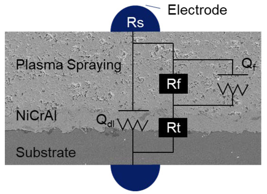
Figure 6.
Equivalent circuit of the alternative current impedance spectrum.
Table 9.
Fitting results of the equivalent circuit of the alternative current impedance spectra of the substrate and plasma spraying coating.
Based on the fitting results, the radii of the two capacitive reactance arcs of VW75 after plasma spraying, particularly the film resistances, are higher than that of the magnesium alloy substrate. This result indicates the presence of barriers against penetration of solution ions into the film layer in the experiment, thereby resulting in the slow migration of solution ions in the dense ceramic layer and bond coat. This process controls the whole electrochemical process and inhibits the increase in the response speed of the anodic reaction. This result is consistent with the Tafel curves.
4. Conclusions
The six-factor and five-level orthogonal experimental table is applied, and the experiments are arranged according to the data in the table. The experimental results are calculated and analyzed by the range analysis method. In this study, the main gas flow is the primary influencing factor of the coating performance, followed by spraying current, spraying speed, powder feed rate, and auxiliary gas flow, successively. However, spraying distance slightly influences the coating performance. The optimal technological parameters are as follows: 875 A of spraying current, 85 mm of spraying distance, 75 SCFH of main gas flow, 45 SCFH of auxiliary gas flow, 400 mm/s of spraying speed, and 30 g/min of powder feed rate. The corresponding HV, density, and rate of deposition are 388, 5.25 g/cm3, and 31.58%, respectively.
The section structure of the plasma spraying coating under optimal conditions is divided into the base layer, bond coat, and ceramic layer. The XRD results indicate that the surface coating is composed of ZrO2.
The electrode potential of magnesium alloy is increased generally after plasma spraying, accompanied with a sharp reduction in the corrosion current. Coating increases the corrosion resistance of the alloy. The EIS results are consistent with the Tafel curves. The corrosion resistance of the magnesium alloy is increased significantly after plasma spraying.
Author Contributions
B.L. the first author and the main writer of the paper, is fully responsible for the design and development of the paper; B.Z. carrying out and proofreading some experiments; M.M. experimental design and data analysis; K.Z. analysis in the research process; Y.L. (Yongjun Li) Analysis of research process; Z.C. development and reinspection of some experiments; Y.L. (Yanhui Liu) proofreading and format modification of the article. All authors have read and agreed to the published version of the manuscript.
Funding
This research was funded by [Achievements Transformation in Jiangsu Province] grant number [BA2017044].
Conflicts of Interest
There is no conflict of interest of the submitted paper.
References
- Aghion, E.; Bronfin, B. Magnesium alloys development towards the 21st century. In Materials Science Forum; Trans Tech Publications Ltd.: Freienbach, Switzerland, 2000; Volume 350, pp. 19–30. [Google Scholar]
- Makhlouf, A.S.H.; Gajarla, Y. Advances in smart coatings for magnesium alloys and their applications in industry. In Advances in Smart Coatings and Thin Films for Future Industrial and Biomedical Engineering Applications; Elsevier: Amsterdam, The Netherlands, 2020; pp. 245–261. [Google Scholar]
- Song, J.F.; She, J.; Chen, D.L.; Pan, F. Latest research advances on magnesium and magnesium alloys worldwide. J. Magnes. Alloy. 2020, 8, 1–41. [Google Scholar] [CrossRef]
- Mathaudhu, S.N.; Nyberg, E.A. Magnesium Alloys in U.S. Military Applications: Past, Current and Future Solutions. In Essential Readings in Magnesium Technology; Springer: Cham, Switzerland, 2016; pp. 71–76. [Google Scholar]
- Aghion, E.; Bronfin, B.; Eliezer, D. The ROLE of the magnesium industry in protecting the environment. J. Mater. Process. Technol. 2001, 117, 381–385. [Google Scholar] [CrossRef]
- García-Rodríguez, S.; López, A.J.; Bonache, V.; Torres, B.; Rams, J. Fabrication, wear, and corrosion resistance of HVOF sprayed WC–12Co on ZE41 magnesium alloy. Coatings 2020, 10, 502. [Google Scholar] [CrossRef]
- Jonda, E.; Atka, L.; Pakiea, W. Microstructure and selected properties of Cr3C2–NiCr coatings obtained by HVOF on magnesium alloy substrates. Materials 2020, 13, 2775. [Google Scholar] [CrossRef] [PubMed]
- Yao, H.L.; Hu, X.Z.; Wang, H.T.; Chen, Q.Y.; Bai, X.B.; Zhang, M.X.; Ji, G.C. Microstructure and corrosion behavior of thermal-sprayed hydroxyapatite/magnesium composite coating on the surface of AZ91D magnesium alloy. J. Therm. Spray Technol. 2019, 28, 495–503. [Google Scholar] [CrossRef]
- Feng, Y.R.; Zhang, Z.M.; Xu, C.J.; GUO, X. Study of Al65Cu23Fe12 coatings on AZ31 magnesium alloy by plasma spraying. Foundry Technol. 2006, 27, 160–162. [Google Scholar]
- Ye, H.; Zhang, J.; Sun, Z.F.; Yang, H.; Zhan, J. Research on plasma spraying nano Al2O3 + 3% TiO2 ceramics onto surface of magnesium alloy. J. Wuhan Univ. Technol. 2004, 4, 9–11. [Google Scholar]
- Wang, D.; Tian, Z.; Shen, L.; Liu, Z.; Hunag, Y. Preparation and characterization of nanostructured Al2O3–13wt.%TiO2 ceramic coatings by plasma spraying. Rare Met. 2009, 28, 465–470. [Google Scholar] [CrossRef]
- Mohammadreza, D.; Yajid, M.A.M.; Yusof, N.M.; Bakhsheshi-Rad, H.R. Fabrication and properties of triplex NiCrAlY/nano Al2O3–13%TiO2/nano TiO2 coatings on a magnesium alloy by atmospheric plasma spraying method. J. Alloys Compd. 2015, 645, 450–466. [Google Scholar]
- Bakhsheshirad, H.R.; Hamzah, E.; Ismail, A.F.; Daroonparvar, M.; Yajid, M.A.M.; Medraj, M. Preparation and characterization of NiCrAlY/nano-YSZ/PCL composite coatings obtained by combination of atmospheric plasma spraying and dip coating on Mg–Ca alloy. J. Alloys Compd. 2016, 658, 440–452. [Google Scholar] [CrossRef]
- Metallic and Related Coatings-Vickers and Knoop Microhardness Tests; Chinese National Standard (GB 9790-1988); Standardization Administration of China: Beijing, China, 1988; pp. 1–16.
Publisher’s Note: MDPI stays neutral with regard to jurisdictional claims in published maps and institutional affiliations. |
© 2020 by the authors. Licensee MDPI, Basel, Switzerland. This article is an open access article distributed under the terms and conditions of the Creative Commons Attribution (CC BY) license (http://creativecommons.org/licenses/by/4.0/).