Article

Aluminum Nitride Nanofilms by Atomic Layer Deposition Using Alternative Precursors Hydrazinium Chloride and Triisobutylaluminum

1
The Faculty of Electrical Engineering and Communication, Brno University of Technology, Technická 3058/10, 616 00 Brno, Czech Republic
2
Central European Institute of Technology, Purkyňova 123, 61600 Brno, Czech Republic
*
Author to whom correspondence should be addressed.
Coatings 2020, 10(10), 954; https://doi.org/10.3390/coatings10100954
Submission received: 13 September 2020 / Revised: 29 September 2020 / Accepted: 30 September 2020 / Published: 3 October 2020
(This article belongs to the Section Thin Films)

Abstract

:
The aim of this study is motivated by the pursuit to investigate the performance of new and as yet untested precursors such as hydrazinium chloride (N2H5Cl) and triisobutylaluminum Al(C4H9)3 in the AlN atomic layer deposition (ALD) process as well as to study effects of successive annealing on the quality of the resulting layer. Both precursors are significantly cheaper than their conventional counterparts while also being widely available and can boast easy handling. Furthermore, Al(C4H9)3 being a rather large molecule might promote steric hindrance and prevent formation of undesired hydrogen bonds. Chemical analysis is provided by X-ray photoelectron spectroscopy (XPS) and secondary-ion mass spectrometry (SIMS) techniques; surface morphology was studied using atomic force microscopy (AFM). Chlorine containing precursors such as AlCl3 are usually avoided in ALD process due to the risk of chamber contamination. However, experimental data of this study demonstrated that the use of N2H5Cl does not result in chlorine contamination due to the fact that temperature needed for HCl molecules to become reactive cannot be reached within the AlN ALD window (200–350 °C). No amount of chlorine was detected even by the most sensitive techniques such as SIMS, meaning it is fully removed out of the chamber during purge stages. A part of the obtained samples was subjected to annealing (1350 °C) to study effects of high-temperature processing in nitrogen atmosphere, the comparisons with unprocessed samples are provided.

1. Introduction

Aluminum nitride is a wide band gap semiconducting material with covalent bonds, which has a hexagonal crystalline structure that is analogous to the structure of zinc sulfide known as wurtzite. It has a wide range of applications in optoelectronics UV detectors, surface acoustic wave devices, piezoelectric energy convertors and other fields; devices that can benefit from this material are: ultraviolet (UV) optoelectronic devices, such as UV light-emitting diodes (LEDs) and UV laser diodes (LDs) [1].
Ever increasing popularity of AlN-based nanostructures is well justified considering the abundance of its remarkable characteristics. Besides having a wide band gap, AlN boasts such properties as: high electrical resistance, high breakdown voltage, mechanical durability, chemical stability, low deposition temperatures and a potential for piezoelectric applications [2]. This material is resistant to high temperatures in inert atmospheres and has a low expansion coefficient [3]. Lower deposition temperatures within the range of 150–400 °C (depending on a chosen method) ensure compatibility of AlN for applications such as post-processing of integrated circuits. Furthermore, it appears to be an appropriate material to be implemented in surface acoustic wave sensors and bulk acoustic wave filters [4]. Taking into consideration that the conventional silicon monolithic systems also require lower temperatures of deposition, AlN seems to be a more favorable option in comparison to other piezoelectric materials such as zinc oxide (ZnO) or zinc zirconate (ZnZrO3) [5]. AlN has also been reported to exhibit resistive switching properties [6].
Being such an attractive semi-conductive material, it is well expected for there to be a plethora of studies and reports featuring AlN deposited by a variety of multiple tools (magnetron sputtering, ion-beam deposition, metalorganic vapor-phase epitaxy etc.) [7,8,9,10,11]. This particular paper focuses on the atomic layer deposition (ALD) method. ALD is a subtype of the bigger group of methods known as chemical vapor deposition (CVD) methods which are employed for obtaining thin films of various materials in vapor phase. The main feature of an ALD is the sequential introduction of the precursors followed by purging stage which increases homogeneity, purity and quality of the films altogether. ALD has established itself as a promising technique in the semiconductor manufacturing process and technologies for energy conversion [12,13,14]. For application in nanoelectronics, it is essential to have atomic precision in materials manufacturing. Over the last decades ALD proved to be a relatively affordable method with high scalability and repeatability while also providing the necessary precision of the atomic layer for films fabrication at the nanoscale level [15,16,17].
Nowadays, the most common precursors for obtaining AlN by ALD are: N2/H2 plasma, ammonia (NH3), aluminum chloride (AlCl3), hydrazine (N2H4) with each having its advantages and deficiencies. The usage of AlCl3 as an aluminum precursor results in considerable chlorine impregnation into the layer, and also leads to chamber contamination. Ammonia requires high energy for activation and is reported for its limited reactivity under temperatures below 475 °C [18,19]. Hydrazine on the other hand has a more favorable thermochemistry but despite the generally positive results, the use of hydrazine (N2H4) is associated with a number of complications, such as transportation difficulties, explosiveness, instability and expensiveness [20]. The two most common precursors nowadays for obtaining AlN seem to be Al(CH3)3 and N2/H2 plasma. There are numerous reports demonstrating the use of these two precursors in deposition of AlN thin films, the quality of which mostly is within reasonable bounds [6,13,14].
However, the search for more affordable and efficient precursors is always a relevant and justifiable task. In this study, we will be exploring alternatives to the well-established precursors.
Triisobutylaluminum (hence TiBA) is a metalorganic compound with an exact formula [(CH3)2CHCH2]3Al or Al(C4H9)3 in a compressed form, which is mostly used as an Al precursor in CVD processes [7,8]. The following reasons speak in favor of choosing TiBA as an alternative Al precursor:
(1) Triisobutylaluminum is 1.7 times cheaper than the conventional Trimethylaluminum according to “Sigmaaldrich”:
Triisobutylaluminum; CAS Number: 100-99-2; Triisobutylaluminum (~97% purity grade); price: USD 147 (100 g); trimethylaluminum; CAS Number: 75-24-1; trimethylaluminum (97% purity grade); price: USD 250 (100 g).
(2) Al(C4H9)3 may actually be a more favorable choice in terms of reactivity with Si and a higher chamber pressure due to its being a larger molecule [21,22].
(3) Novelty factor—we have already seen multiple times AlN films grown using conventional precursors, so it seems only reasonable to test out something new, especially when there is no apparent reason why Al(C4H9)3 should perform poorer than the well-established Al(CH3)3.
Much like TiBA, N2H5Cl is a relatively cheap compound (USD 62 for 100 g according to Sigma-Aldrich) and thus seems to be an attractive choice for nitrogen precursor. Another aspect which speaks in favor of N2H5Cl lies in the fact that, although it requires some basic precaution measures it is much easier to handle compared to hydrazine in its pure form [23]. As was stated above, chlorine is an aggressive element that might lead to the instrument contamination, which is why chlorine-containing precursors are usually overlooked when it comes to ALD. However, as will be demonstrated in the experimental section, the use of hydrazinium chloride does not result in chlorine contamination since HCl into which N2H5Cl decomposes upon entering the ALD chamber never reaches energy to become reactive and is removed out of the chamber as a waste product.
Annealing in nitrogen is known to produce a positive effect on the quality of AlN thin films [10,24,25], hence, we also performed high-temperature annealing of the deposited layers. Simplification, optimization and price reduction in the technological aspects of obtaining AlN films will help in creating a single technological cycle for obtaining products working in the UV spectral region, buffer layers for LED structures, as well as piezo-crystalline layers in NEMS structures.

2. Experimental Detail

Deposition of the AlN thin films was carried out on the ALDCERAM ML-200 setup located in the physics department of the Dagestan State University. Prior to deposition, substrates were cleaned with acetone, isopropanol and dried in a stream of UHP nitrogen. Then the substrates were placed in the ALD chamber and were kept there for ~30 min until the chamber temperature reached 250 °C, allowing to initiate deposition. The container with TiBA has been heated to its vaporization temperature (86 °C).
In total, 150 ALD cycles were performed with the following parameters: the exposure time of TiBA Al(C4H9)3 was 4 s, after which the reactor chamber was purged with the inert gas (N2) for 5 s; the next stage was the introduction of hydrazinium chloride N2H5Cl, the duration of which was 0.2 s followed by a nitrogen purging of 30 s; then, again introduction of Al(C4H9)3 for 4 s, followed by a nitrogen purging of 30 s. The image of the ALD equipment used is presented in Figure 1a. One cycle of the ALD process, as well as the change in the chamber pressure during precursor introduction, is presented in Figure 1b. The gradual decrease in the chamber pressure during precursor exposure time indicates chemisorption which takes place on the substrate.
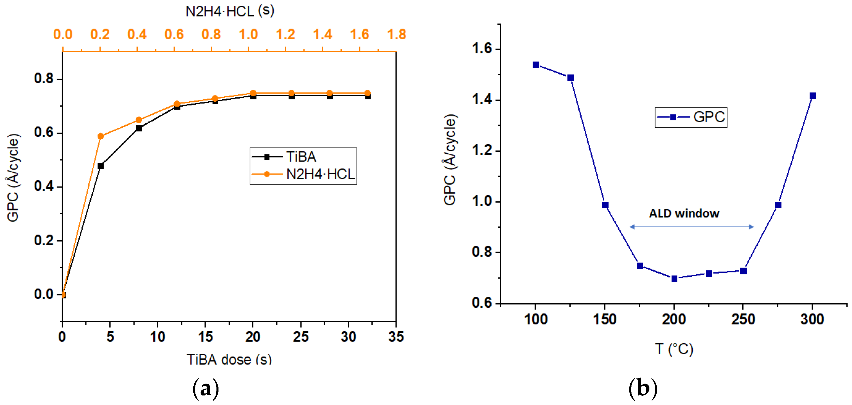
Growth per cycle (GPC) as a function of precursor exposure time and temperature is given in Figure 2a,b. The values were calculated from spectroscopic ellipsometry data on thickness. The average growth rate was found to be ~0.072 nm/cycle. The stable value of GPC is reached at ~1 s of exposure for N2H5Cl and at ~20 s for TiBA (Figure 2a). According to Figure 2b, the self-limiting growth takes place in the temperature range of 150–250 °C. The rapid increase in GPC after 250 °C might be attributed to self-decomposition of TiBA as is the case for TMA after 300 °C [26].
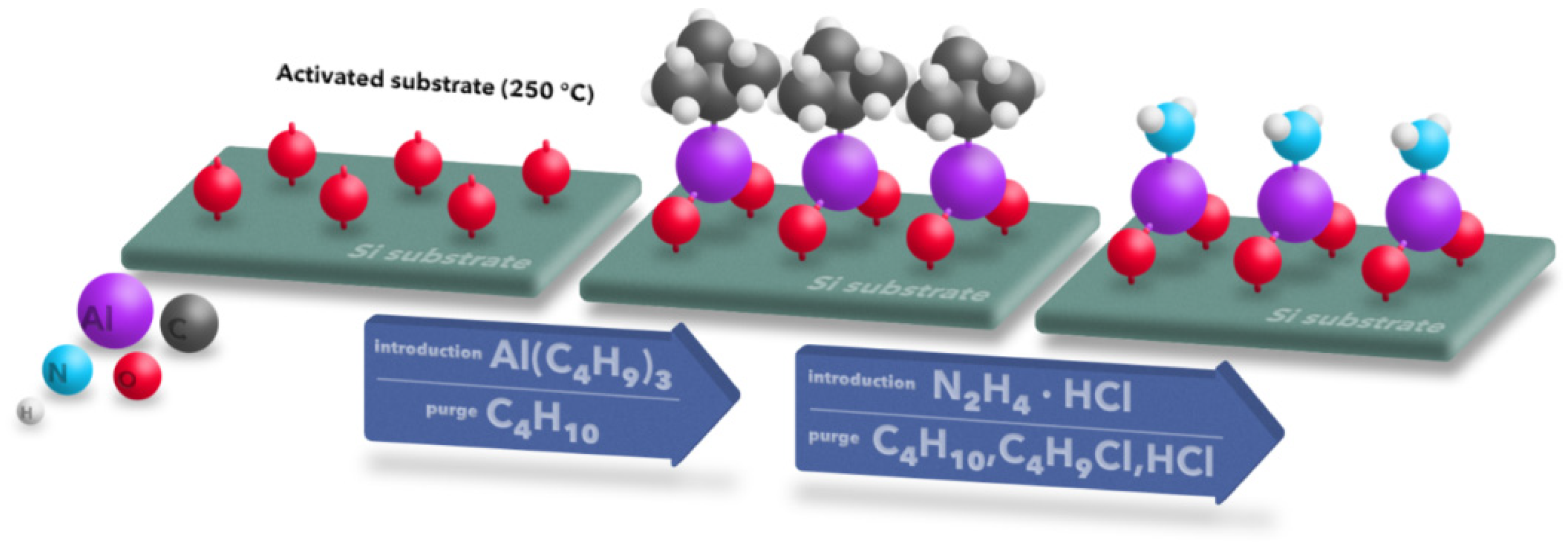
For informative and illustrative reasons, we include the scheme of an assumed ideal ALD process presented in Figure 3. In the middle we can see the result of the reaction of TiBA with the activated substrate on the left; C4H10 is a waste product. On the right is the result of the reaction of N2H5Cl with the surface of the middle product; C4H10, C4H9Cl and HCl are the expected waste products.
Heating of the container with hydrazinium chloride was carried out at temperature up to 90 °C (Tm of N2H5Cl ~ 89 °C). The deposition temperature of the sample batch used for analysis was 250 °C, which is within the AlN ALD window according to our GPC measurements and a plethora of other studies [2,3,6,12,13,18,20]. A part of the obtained films has been also subjected to a high-temperature annealing (1350 °C) in the nitrogen (N2) atmosphere for 1 h to remove possible impurities (in particular, hydrogen impurities).
AFM images were taken on a Scanning Probe Microscope Bruker Dimension Icon (ICON-SPM) in tapping mode. Gwyddion software was used for processing and extracting values for surface roughness.
Kratos Analytical Axis Supra instrument with Al Kα excitation source and emission current of 15 mA was employed to perform XPS analysis. Wide spectrum was taken at 80 eV. High resolution spectra were taken at 20 eV. All spectra were calibrated by shifting major C 1s peak (C–C bond) to 284.8 eV. The presented spectra were made in CasaXPS software (Version 2.3.19.PR1.0), SG linear smoothing and background subtraction tools were used.
SIMS analysis was performed on ION-TOF TOF.SIMS 5 instrument in positive mode. The instrument utilizes the dual gun mode of analysis. An oxygen gun with energy of 2 KeV was used for aggressive sputtering (material removal only), whereas a Bi gun provides a much slower sputtering rate and the secondary ions produced by it are collected by the analyzer. The area of the crater was chosen to be 100 nm × 100 nm and the area of analysis 50 nm × 50 nm. The 3D modelling was carried out using the native software SurfaceLab 7.1 provided by the manufacturer.
All aforementioned instruments used for analysis of the obtained samples are located at the CEITEC Nano Research Infrastructure in Brno, Czech Republic.

3. Experimental Data

3.1. Atomic Force Microscopy (AFM) and X-ray Diffraction (XRD) Data

In our study, the AFM method has been employed to investigate topography of AlN thin films before and after annealing at 1350 °C. The obtained AFM images are presented in Figure 4.
Obtained results enable observation of changes caused by annealing of the films (Figure 4a,b). AFM data confirm that annealing contributes to the increase in roughness; coalescence of particles on the surface is likely to occur as well as removal of the residual hydrocarbon bonds from the film.
Annealing also leads to an increase in the topography uniformity and regularity of the surface texture (Figure 4c,d).
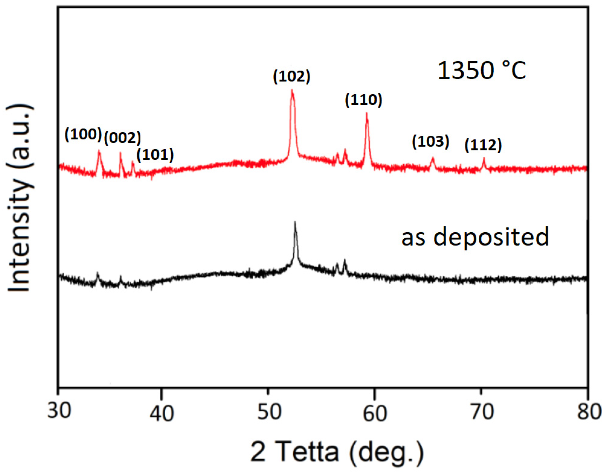
We assume that the film is in the crystallization stage, that is, in the intermediate state between amorphous and polycrystalline. Annealing completes the crystallization process which is proved by the XRD spectra provided in Figure 5. The increase in existing reflections and appearance of new ones indicated that the annealed films consist of crystallites of a larger size [24,27]. The root mean square of the surface roughness (Sa) for as-deposited AlN layer equaled to 0.23 nm which is within the norm for ALD AlN [15,28]. However, we can observe a rather significant increase after annealing of up to 0.84 nm, which suggests once again that temperature treatment promotes the tendency of the layer to coalesce into clusters. Huan-Yu Shih et al. report in their work an increase in the similar magnitude (from 0.223 nm to 0.663 nm) after annealing [18]. An increase in surface roughness can be explained by an increase in the grain size in the AlN layer, resulting in an improvement of crystallinity. In addition, the high conformity of films obtained by the ALD method leads to the filling of surface pits and pinholes with each deposited layer, which helps to reduce the density of pits or point defects on the surface. In addition, thermal stress caused by the difference in the thermal expansion coefficient between AlN and silicon can lead to formation of pits and cracks.

3.2. X-ray Photoelectron Spectroscopy (XPS) Data

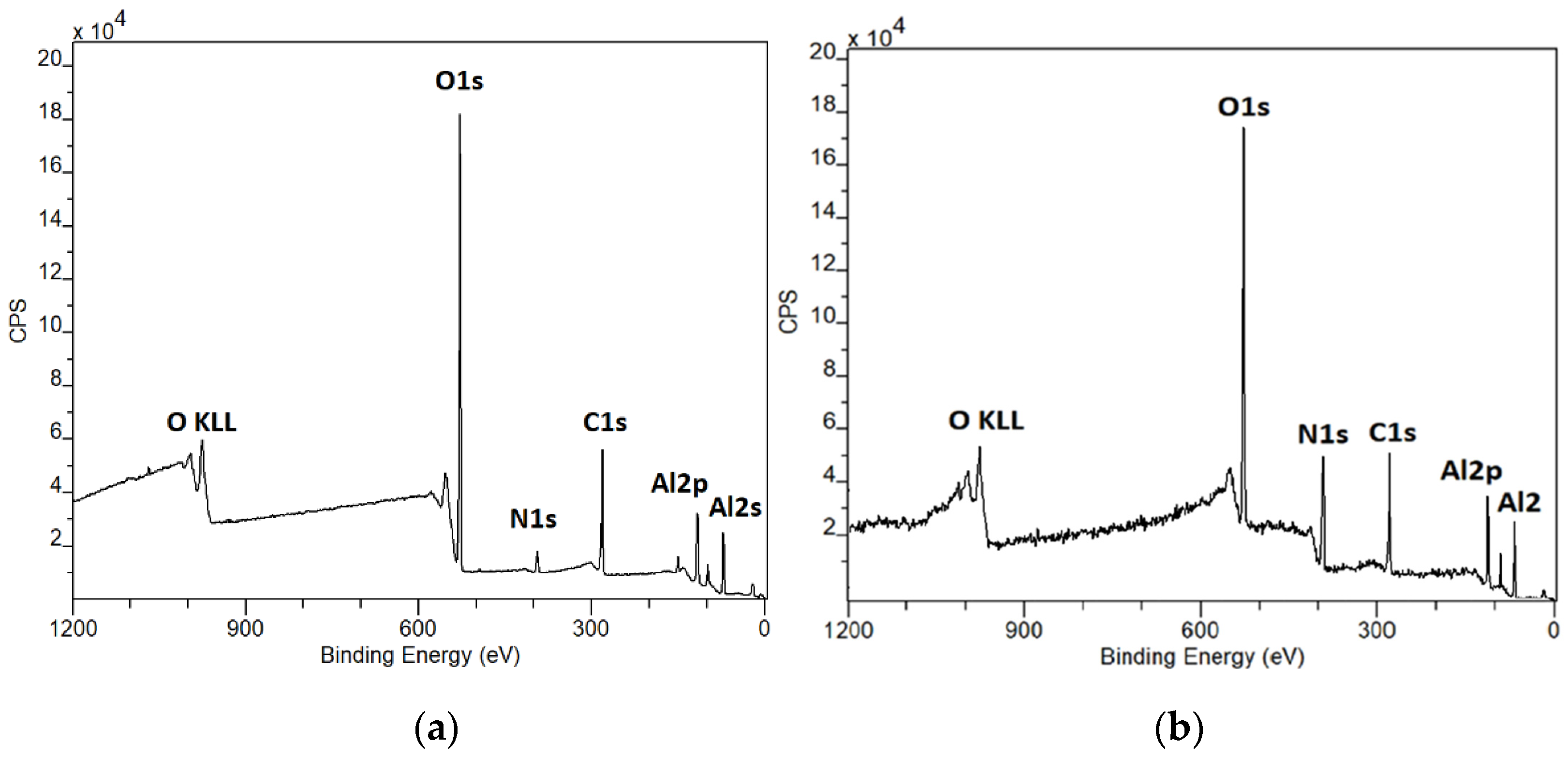
XPS comparison of as-deposited and annealed samples of AlN. Annealing was carried out in N2 atmosphere at 1350 °C for 1 h, heating/cooling rate was at 100 °C/min. All spectra have been calibrated by setting the C–C bond at 248.8 eV. The most important and notable change is the considerable increase in N1s peak intensity after annealing (Figure 6). Distinguishing nitrogen peak on the wide-spectrum of as-deposited films is somewhat challenging, which is why it is best instead to consult the high-resolution spectra provided below. The proneness of AlN to extensive oxidation is a notorious issue reported by multiple studies [6,17,18,29]. Carbon is also an unavoidable contaminant occurring from atmosphere [6,17,30].
The N 1s peak on the wide spectrum of unannealed samples is of rather low intensity; nonetheless it is still well-defined in high-resolution mode. We speculate that intensity of the nitrogen peak might be enhanced by increasing exposure time of N2H5Cl, since the optimal saturation may not have been reached. However, this minor detail should by no means be a hindrance to drawing conclusions regarding the efficiency of N2H5Cl. As will be demonstrated in the discussion section, N2H5Cl basically decomposes into hydrazine in the ALD chamber and the latter has already demonstrated positive results as a nitrogen precursor for AlN thin films [20]. Moreover, imperfections of the ALD process have then been rectified by consecutive annealing in nitrogen.
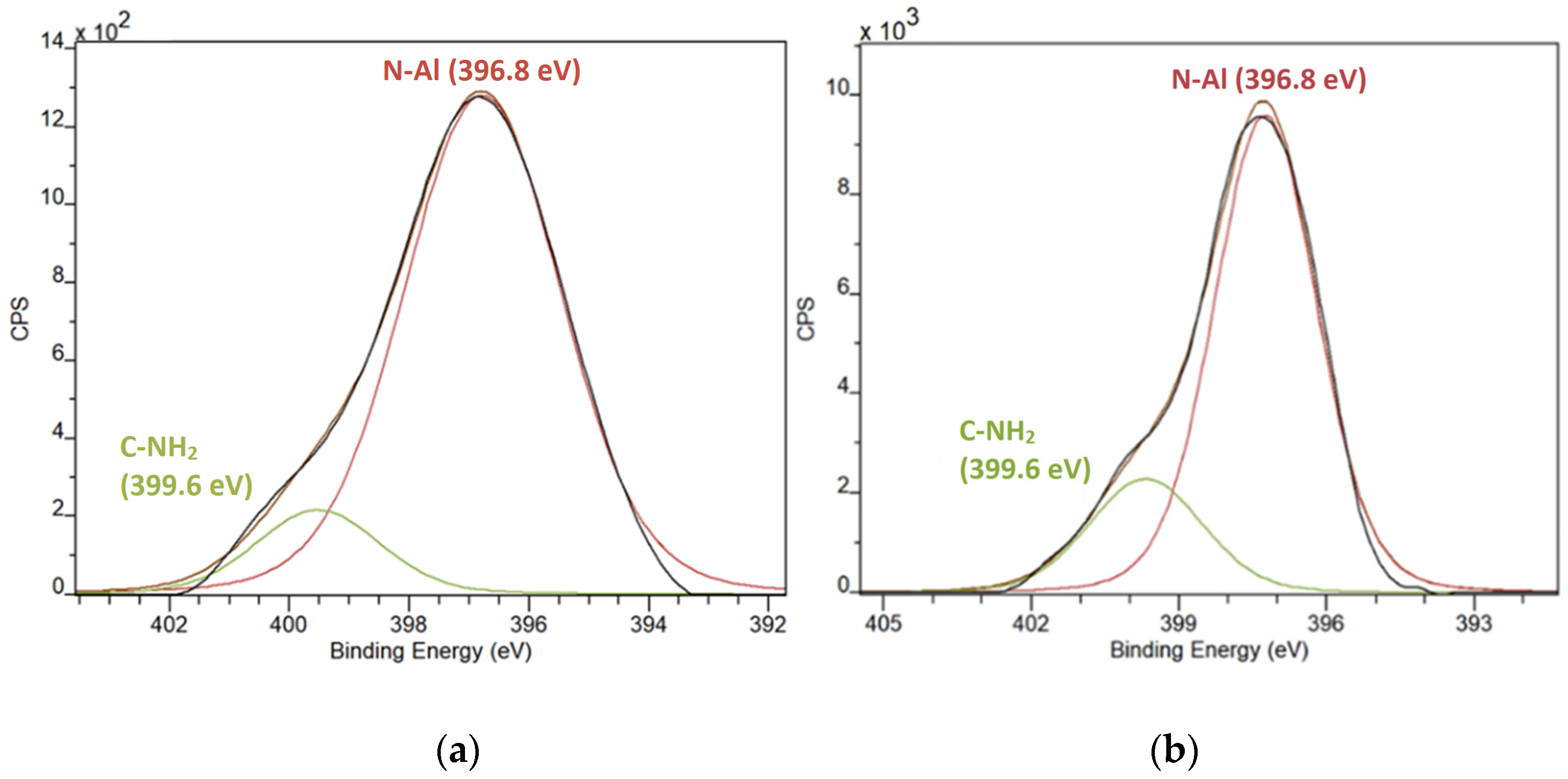
Both peaks are located at ~396.8 eV which is the energy widely attributed to Al–N bond [9,17,31,32,33]. The subpeak at ~400 eV is ascribed to C–NH2 bonds (Figure 7). It is also worth emphasizing that, despite expectations, neither of the N 1s peaks shows any sign of oxidization; C–NH2 bonds apparently occur as a result of side reaction between the two used precursors and remain unaffected by high-temperature annealing given the strong nature of these bonds. The dramatic increase in Al–N bond intensity is explained by influx of new nitrogen atoms during the annealing in the N2 flow which induced reaction with the Al atoms still engaged in Al–Al bonds.
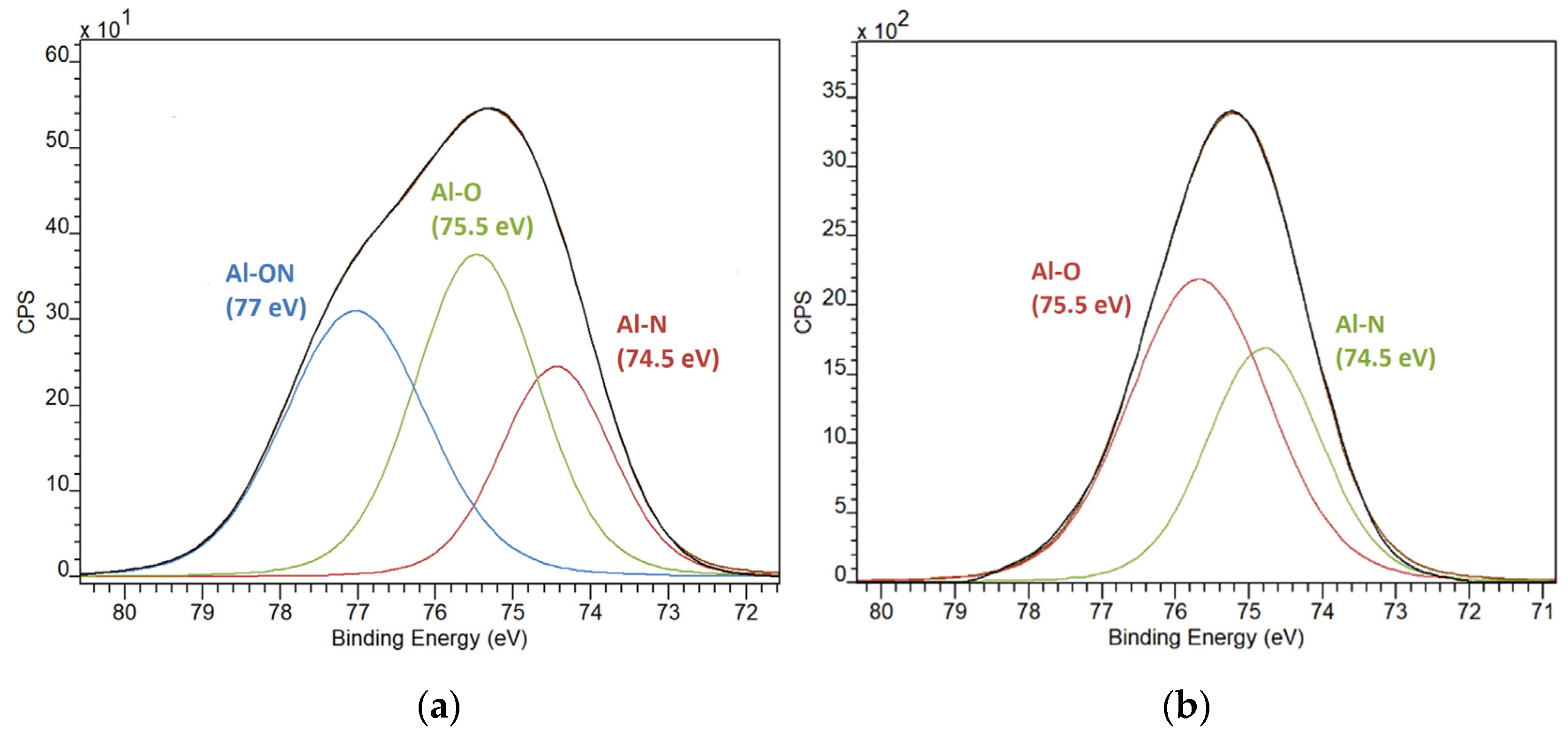
Figure 8a shows that the Al 2p peak can be deconvoluted into several subpeaks, the major one at 75.5 eV is related to Al–O and the smaller at 74.4 eV is attributed to Al–N [10,17,30,34,35,36]. Both peaks persist after high-temperature treatment (Figure 8b) and remain at the same binding energies. However, there is also a third peak that can be observed for as-deposited samples which is located at 77 eV. The literature is very scant on that matter, there is a record on Al–F bond located at 77 eV [37], however, no fluoride has been detected in our wide spectra, which is why this third peak more likely belongs to the Al–O bond affected by nitrogen as this is suggested by P.W. Wang et al. [38].
Extensive study of literature compels us to conclude that there is no consensus whatsoever among researchers on the exact position of the Al–N bond and the records vary greatly. Which is why we are also including a table with values of Al–N binding energy reported by other research studies (Table 1).
Analysis of C 1s peak (Figure 9) shows the presence of different organic bonds, which are O–C=O at 2884 eV for as-deposited sample and O–C=O 287.6 eV, C–O–C 285.9 at eV for annealed sample [6,25,30]. The formation of new types of bonds is well expected when high temperature treatment is applied (Figure 9b), especially with a reactive element such as oxygen, the coalescence of the layer during extreme heating is also a promoting factor for such reactivity. The new C–O–C is likely to be formed not only from the C atoms in the C–C bond but also as a result of breaking of π–π bonds in O–C=O which are less stable in comparison with σ bonds in C–O–C.
O1s high-resolution spectra are presented in Figure 10 and there we can observe the same tendency as in the C 1s peak a shift from C=O bond at 533.2 eV to C–O–C bond at 532.9 eV. The Al–O bond at 531.6 eV is present in both scenarios due to AlN’s high affinity to oxidation [6,17,18,29,30].

3.3. Secondary-Ion Mass Spectrometry

To further investigate the chemical composition as well as to provide depth profiling of the films obtained, the secondary-ion mass spectrometry (SIMS) was utilized in time-of-flight mode. The main principle of this mode is that different ions require different periods of time to reach the analyzer due to mass discrepancy; this period of time is then counted and used to detect and identify an ion using the software with an extensive built-in database.
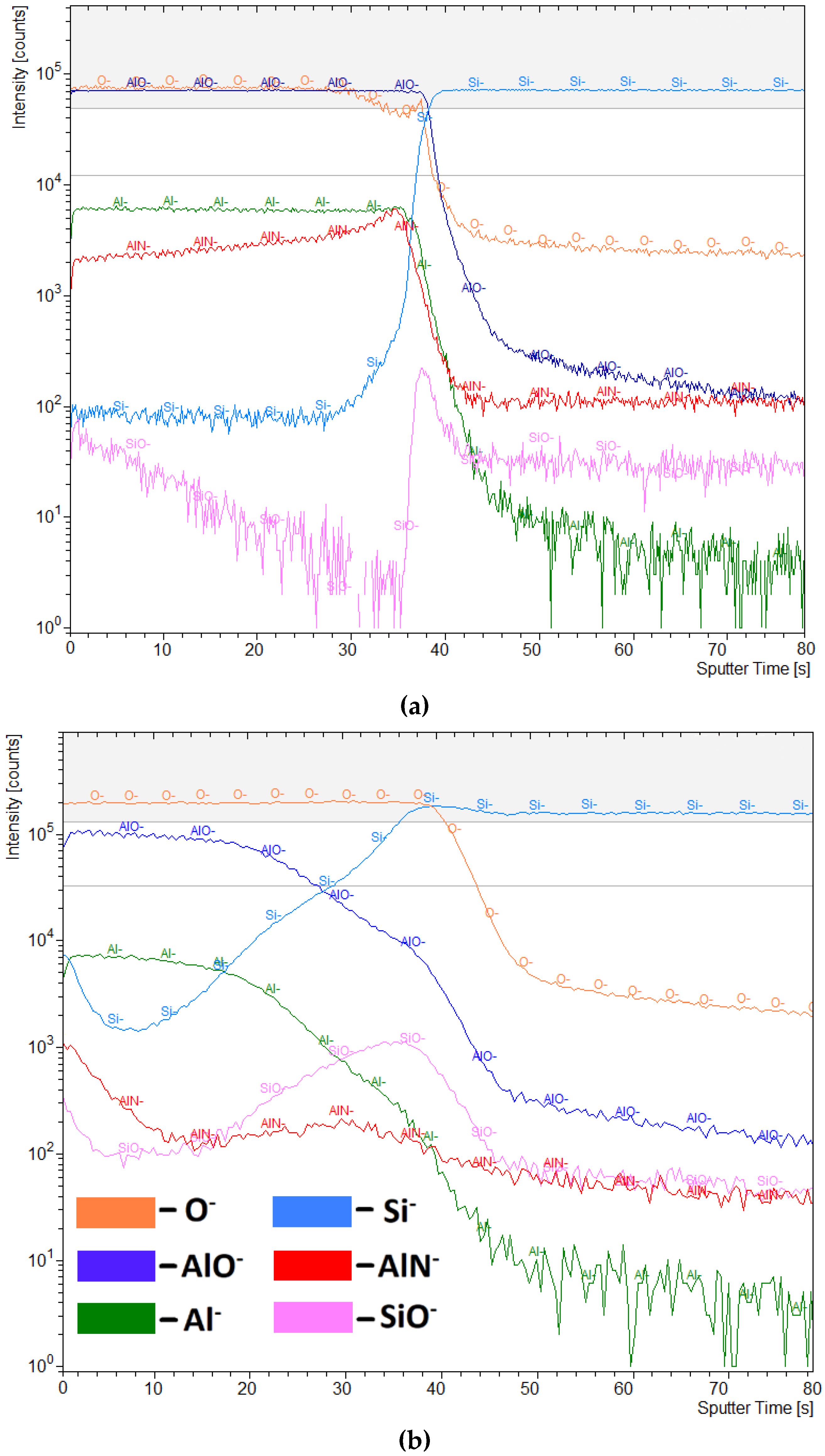
The SIMS equipment used in this work utilizes two ion-guns, one of which is used for sputtering only and the other with much lower energy is used for analysis. For sputtering, we used oxygen ions with energy of 2 keV for creating a crater and bismuth ions for analyzing the sputtered area along the way. Every 2 s of sputtering was followed by 3 s of analysis. The area of the crater was 200 nm × 200 nm; the area of analysis was 50 nm × 50 nm. The depth profiling spectra for O, AlO, Si, Al, AlN and SiO for both annealed and unannealed samples are given in Figure 11a,b.
Sputter time on X-axis is 80 s which can be translated into approximately 20 nm of crater depth. The Si spectrum maximizes at around 42 s which translates into ~8 nm, indicating the end of the layer and beginning of the substrate. At the same point, we can observe a rapid decrease in intensity of Al and AlN peaks. SiO spectrum exhibits a hill between 20 and 50 s which is the region of the substrate oxidization. It is worth mentioning that SIMS spectra are unusable for quantification. It can be noticed that the intensity of O and AlO ions is high, which also correlates with XPS data. As we mentioned in the section describing XPS results, the extensive oxidization of AlN films grown by ALD is a notorious issue and by no means limited to our particular case [6,17,18,29]. Partially, the amount of oxygen can be explained by the fact that we utilized oxygen primary beam, a portion of that beam is scattered back to the analyzer either in the form of pure ions or ions formed by the interaction with the atoms in the sample. Thus, the real amount of oxygen or oxygen containing ions is significantly lower.
In Figure 10 below, images of 2D and 3D distribution of ions are presented. A sample without temperature treatment (Figure 12a) shows a rather uniform distribution of AlN ions, whereas there is a noticeable grain of ~20 nm × 20 nm containing AlN on a sample that has undergone temperature treatment (Figure 12b); such grains have been spotted throughout the entire surface of all samples. This discovery unambiguously confirms the clustery nature of the layer on annealed samples. The 3D distribution of the grain is presented in Figure 12c.
Now it is important to state here, that there is a known issue that comes into play while modeling 3D distribution of elements on uneven surfaces which lies in the fact that the model begins with the lowest point on the surface and all the features (including grains) that are higher than the lowest point are shown to be distributed downwards in the model instead of upward. So the continuation of the AlN grain (dark green color) which we see after the SiO2 native layer (purple color) actually resides above the 3D model and not in the bulk of the substrate as the picture misleadingly implies.

4. Discussion

The experimental results suggest clusterization of the grown layer after annealing. The plethora of different peaks and artefacts observed in the XPS spectra is likely due to the fact that XPS beam captures clusters of AlN as well as part of the oxidized substrate.
The first step was the introduction of the Al precursor; the low-energy metalorganic bonds can be broken at relatively low temperatures (~200–250 °C) [7,8]. The ion formed as a result will connect with the surface oxygen:
[substrate]-SiO2 + Al(C4H9)3 → [substrate]-Si–O–Al–(C4H9)2 + C4H9+
Then, the chamber is purged and hydrazinium chloride is introduced. The hydrazinium chloride salt first decomposes into hydrazine and hydrogen chloride [43].
[N2H5]+∙Cl → N2H4 + HCl
It is worth indicating that no presence of the latter has been detected neither by XPS nor SIMS analyses, which means HCl molecules are completely removed out of the chamber during the purge stage. It has to do with the fact the that the deposition temperature is not nearly enough to ionize HCl, hydrazine on the other hand can be activated at temperatures <250 °C [20] and, theoretically, reaction should proceed as following:
N2H4 → (–N–H2)2
[substrate]-Si–O–Al– (C4H9)2 + (–N–H2)2 → [substrate]-Si–O–Al–N– (H)2 + C4H10
Further annealing is necessary since the optimal saturation with nitrogen atoms has not been reached and oxygen atoms that might have been in the chamber have much higher affinity to Al than nitrogen atoms. Annealing in nitrogen is supposed to rectify inadequacies of the ALD process and improve the quality of AlN in general (crystallization).
Thus, the deposited samples have then been submitted to high-temperature (1350 °C) annealing in nitrogen atmosphere which promoted formation of nitridic and oxynitridic bonds in different proportions throughout the sample.
Al2O3 + N2 → Al–N–O–(main reaction)
Al2O3 + N2 → Al–O–N–(side reaction)
The XPS spectra unambiguously suggest an increased amount of Al–N bonds for annealed samples, which is why we assume that some of the Al–O–Al and Al–O–N bonds are decomposed under the thermal stress and new Al–N–Al and Al–N–O bonds are formed either through reaction with molecular nitrogen of through diffusion process. The fact that molecular nitrogen might become reactive at temperatures exceeding 1000 °C has also been reported by C. F. Cullis and J. G. Yates in their study on reaction of carbon with molecular nitrogen [44]. The diffusion implies the release of nitrogen atoms that are seated deep down in the layer, beyond the range of the X-ray. Upon release, these atoms are distributed equally throughout the layer forming new bonds. To corroborate our assumption, we refer to the work of Cao D. et al. [25] who also studied the effect of high-temperature annealing on AlN films deposited by PE-ALD and reported similar tendency. The overall observation in their work is that high-temperature annealing seems to promote formation of new Al–N bonds and causes decomposition of Al–O–N bonds. Furthermore, they also indicated that the annealing of AlN in a nitrogen atmosphere generally improves the quality of the film while eliminating the defects that might have occurred during the growth through diffusion and rearrangement of the atoms. Annealing also produces a favorable effect on the crystalline qualities of the layer.

5. Conclusions

The main purpose of this work was to test out the new cheap and accessible precursors, hydrazinium chloride (N2H5Cl) and triisobutylaluminum (TiBA), in the AlN ALD process. Obtained samples have been analyzed using AFM, XPS and SIMS methods. The data collected from these analyses incline us to conclude that optimal saturation with nitrogen might not have been reached; however, temperature treatment fixed that issue and resulted in the film taking the “clustery” nature. These small crystals with diameters of ~20 mm × 20 nm cover the substrate in a uniform manner. Overall, it can be said that hydrazinium chloride showed positive results, though of course with several stipulations. We believe that by optimization of the technology and growing films with higher thickness, more reassuring results can be achieved. Thus, based on the data provided within the scope of this study, additional research regarding these precursors is warranted.

Author Contributions

Data curation, R.D.; Formal analysis, R.D.; Resources, P.T. and P.S.; Supervision, D.S. and P.S.; Visualization, L.Š.; Writing—original draft, R.D.; Writing—review & editing, R.D. and D.S. All authors have read and agreed to the published version of the manuscript.

Funding

Research described in this paper was financially supported by the Ministry of Education, Youth and Sports of the Czech Republic under the project CEITEC 2020 (LQ1601), by the National Sustainability Program under grant LO1401 and by Internal Grant Agency of Brno University of Technology, grant No. FEKT-S-20-6352. The research infrastructure of the SIX Center was used in this work. CzechNanoLab project LM2018110 funded by MEYS CR is gratefully acknowledged for the financial support of the measurements/sample fabrication at CEITEC Nano Research Infrastructure.

Conflicts of Interest

The authors declare that they have no conflict of interest.

References

  1. Nieminen, M.; Lehto, S.; Niinistö, L. Atomic layer epitaxy growth of AlN thin films. J. Mater. Chem. 2001, 11, 3148–3153. [Google Scholar] [CrossRef]
  2. Van Bui, H.; Wiggers, F.B.; Gupta, A.; Nguyen, M.D.; Aarnink, A.A.I.; De Jong, M.P.; Kovalgin, A.Y. Initial growth, refractive index, and crystallinity of thermal and plasma-enhanced atomic layer deposition AlN films. J. Vac. Sci. Technol. A Vac. Surf. Film 2015, 33, 01A111. [Google Scholar] [CrossRef]
  3. Tarala, V.A.; Altakhov, A.S.; Martens, Y.A.; Lisitsyn, S.V. Growing aluminum nitride films by Plasma-Enhanced Atomic. Inorg Mater. 2015, 51, 728–735. [Google Scholar] [CrossRef]
  4. Andrei, A.; Krupa, K.; Jozwik, M.; Delobelle, V.; Hirsinger, L.; Gorecki, C.; Nieradko, L.; Meunier, C. AlN as an actuation material for MEMS applications. The case of AlN driven multilayered cantilevers. Sens. Actuators A Phys. 2008, 141, 565–576. [Google Scholar] [CrossRef]
  5. Giordano, C.; Ingrosso, I.; Todaro, M.; Maruccio, G.; De Guido, S.; Cingolani, R.; Passaseo, A.; De Vittorio, M. AlN on polysilicon piezoelectric cantilevers for sensors/actuators. Microelectron. Eng. 2009, 86, 1204–1207. [Google Scholar] [CrossRef]
  6. Zhang, J.; Zhang, Q.; Yang, H.; Wu, H.; Zhou, J.; Hu, L. Bipolar resistive switching properties of AlN films deposited by plasma-enhanced atomic layer deposition. Appl. Surf. Sci. 2014, 315, 110–115. [Google Scholar] [CrossRef]
  7. Găluşcă, D.G.; Perju, M.C.; Nejneru, C.; Nergiş, D.D.B.; E Lăzărescu, I. Aluminum coating influence on nitride layer performance deposited by MO-CVD in fluidized bed on austenitic stainless steel substrate. IOP Conf. Ser. Mater. Sci. Eng. 2018, 374. [Google Scholar] [CrossRef] [Green Version]
  8. Czok, G.S.; Werther, J. Liquid spray vs. gaseous precursor injection—Its influence on the performance of particle coating by CVD in the fluidized bed. Powder Technol. 2006, 162, 100–110. [Google Scholar] [CrossRef]
  9. Meng, J.P.; Liu, X.P.; Fu, Z.Q.; Wang, X.J.; Hao, L. Thermal stability of AlN films prepared by ion beam assisted deposition. Appl. Surf. Sci. 2015, 347, 109–115. [Google Scholar] [CrossRef]
  10. Jose, F.; Ramaseshan, R.; Dash, S.; Bera, S.; Tyagi, A.K.; Raj, B. Response of magnetron sputtered AlN films to controlled atmosphere annealing. J. Phys. D Appl. Phys. 2010, 43, 075304. [Google Scholar] [CrossRef]
  11. Ma, D.; Liu, H.; Deng, Q.; Yang, W.; Silins, K.; Huang, N.; Leng, Y. Optimal target sputtering mode for aluminum nitride thin film deposition by high power pulsed magnetron sputtering. Vacuum 2019, 160, 410–417. [Google Scholar] [CrossRef]
  12. Johnson, R.W.; Hultqvist, A.; Bent, S.F. A brief review of atomic layer deposition: From fundamentals to applications. Mater. Today 2014, 17, 236–246. [Google Scholar] [CrossRef]
  13. Ozgit, C.; Donmez, I.; Alevli, M.; Biyikli, N.; Ozgit-Akgun, C. Self-Limiting low-temperature growth of crystalline AlN thin films by plasma-enhanced atomic layer deposition. Thin Solid Films 2012, 520, 2750–2755. [Google Scholar] [CrossRef] [Green Version]
  14. Goerke, S.; Ziegler, M.; Ihring, A.; Dellith, J.; Undisz, A.; Diegel, M.; Anders, S.; Huebner, U.; Rettenmayr, M.; Meyer, H.G. Atomic layer deposition of AlN for thin membranes using trimethylaluminum and H2/N2 plasma. Appl. Surf. Sci. 2015, 338, 35–41. [Google Scholar] [CrossRef]
  15. Sadeghpour, S.; Ceyssens, F.; Puers, R. Crystalline growth of AlN thin films by atomic layer deposition. J. Phys. Conf. Ser. 2016, 757, 6–11. [Google Scholar] [CrossRef]
  16. Shih, H.Y.; Lee, W.H.; Kao, W.C.; Chuang, Y.C.; Lin, R.M.; Lin, H.C.; Shiojiri, M.; Chen, M.-J. Low-Temperature atomic layer epitaxy of AlN ultrathin films by layer-by-layer, in-situ atomic layer annealing. Sci. Rep. 2017, 7, 1–8. [Google Scholar] [CrossRef] [Green Version]
  17. Motamedi, P.; Cadien, K. XPS analysis of AlN thin films deposited by plasma enhanced atomic layer deposition. Appl. Surf. Sci. 2014, 315, 104–109. [Google Scholar] [CrossRef]
  18. Rontu, V.; Sippola, P.; Broas, M.; Ross, G.; Sajavaara, T.; Lipsanen, H.; Paulasto-Kröckel, M.; Franssila, S. Atomic layer deposition of AlN from AlCl3 using NH3 and Ar/NH3 plasma. J. Vac. Sci. Technol. A Vac. Surf. Film 2018, 36, 021508. [Google Scholar] [CrossRef] [Green Version]
  19. Chen, Z.; Zhu, Z.; Härkönen, K.; Salmi, E. Batch processing of aluminum nitride by atomic layer deposition from AlCl3 and NH3. J. Vac. Sci. Technol. A 2019, 37, 020925. [Google Scholar] [CrossRef]
  20. Abdulagatov, A.I.; Ramazanov, S.; Dallaev, R.S.; Murliev, E.K.; Palchaev, D.; Rabadanov, M.K.; Abdulagatov, I.M. Atomic layer deposition of aluminum nitride using tris(diethylamido)aluminum and hydrazine or ammonia. Russ. Microelectron. 2018, 47, 118–130. [Google Scholar] [CrossRef]
  21. Jones, A.C.; Hitchman, M.L. Overview of Chemical Vapor Deposition; Chemical Vapor Deposition: Precursors, Processes and Applications; Jones, A.C., Hitchman, M.L., Eds.; Royal Society of Chemistry: London, UK, 2009; pp. 327–328. [Google Scholar]
  22. Kermagoret, A.; Kerber, R.N.; Conley, M.P.; Callens, E.; Florian, P.; Massiot, D.; Copéret, C.; Delbecq, F.; Rozanska, X.; Sautet, P. Triisobutylaluminum: Bulkier and yet more reactive towards silica surfaces than triethyl or trimethylaluminum. Dalton Trans. 2013, 42, 12681–12687. [Google Scholar] [CrossRef] [PubMed]
  23. Cellier, P.P.; Spindler, J.-F.; Taillefer, M.; Cristau, H.-J. Pd/C-catalyzed room-temperature hydrodehalogenation of aryl halides with hydrazine hydrochloride. Tetrahedron Lett. 2003, 44, 7191–7195. [Google Scholar] [CrossRef]
  24. Xiao, S.; Suzuki, R.; Miyake, H.; Harada, S.; Ujihara, T. Improvement mechanism of sputtered AlN films by high-temperature annealing. J. Cryst. Growth 2018, 502, 41–44. [Google Scholar] [CrossRef]
  25. Cao, D.; Cheng, X.; Xie, Y.-H.; Zheng, L.; Wang, Z.; Yu, X.; Wang, J.; Shen, D.; Yu, Y. Effects of rapid thermal annealing on the properties of AlN films deposited by PEALD on AlGaN/GaN heterostructures. RSC Adv. 2015, 5, 37881–37886. [Google Scholar] [CrossRef] [Green Version]
  26. Liu, S.; Peng, M.; Hou, C.; He, Y.; Li, M.; Zheng, X. PEALD-Grown Crystalline AlN Films on Si (100) with Sharp Interface and Good Uniformity. Nanoscale Res. Lett. 2017, 12, 1–6. [Google Scholar] [CrossRef] [Green Version]
  27. Ozgit-Akgun, C.; Goldenberg, E.; Okyay, A.K.; Biyikli, N. Hollow cathode plasma-assisted atomic layer deposition of crystalline AlN, GaN and AlxGa1−xN thin films at low temperatures. J. Mater. Chem. C 2014, 2, 2123–2136. [Google Scholar] [CrossRef] [Green Version]
  28. Motamedi, P.; Cadien, K. Structural and optical characterization of low-temperature ALD crystalline AlN. J. Cryst. Growth 2015, 421, 45–52. [Google Scholar] [CrossRef]
  29. Kim, H.; Kim, N.D.; An, S.C.; Yoon, H.J.; Choi, B.J. Improved interfacial properties of thermal atomic layer deposited AlN on GaN. Vacuum 2019, 159, 379–381. [Google Scholar] [CrossRef]
  30. Rosenberger, L.; Baird, R.; McCullen, E.; Auner, G.; Shreve, G. XPS analysis of aluminum nitride films deposited by plasma source molecular beam epitaxy. Surf. Interface Anal. 2008, 40, 1254–1261. [Google Scholar] [CrossRef]
  31. Lin, Y.-H.; Hsu, J.-C.; Ding, Y.; Wang, P.W. Optical properties of high transmittance aluminum oxynitride thin films for spectral range from near ultraviolet to visible. Opt. Rev. 2009, 16, 400–403. [Google Scholar] [CrossRef]
  32. Morgan, D.J. Imaging XPS for industrial applications. J. Electron Spectrosc. Relat. Phenom. 2018, 231, 109–117. [Google Scholar] [CrossRef]
  33. Reddy, N.; Bera, P.; Reddy, V.R.; Sridhara, N.; Dey, A.; Anandan, C.; Sharma, A.K. XPS study of sputtered alumina thin films. Ceram. Int. 2014, 40, 11099–11107. [Google Scholar] [CrossRef]
  34. Chen, D.; Xu, D.; Wang, J.; Zhang, Y. Investigation of chemical etching of AlN film with different textures by X-ray photoelectron spectroscopy. J. Phys. D Appl. Phys. 2008, 41. [Google Scholar] [CrossRef]
  35. Radwan, A.B.; Shakoor, R.A. Aluminum nitride (AlN) reinforced electrodeposited Ni–B nanocomposite coatings. Ceram. Int. 2020, 46, 9863–9871. [Google Scholar] [CrossRef]
  36. Graniel, O.; Kempiński, M.; Jancelewicz, M.; Zaleski, K.; Jurga, S.; Smyntyna, V. Structural and XPS characterization of ALD Al2O3 coated porous silicon. Vacuum 2015, 113, 52–58. [Google Scholar] [CrossRef]
  37. Zhang, T.; Park, J.Y.; Huang, W.; Somorjai, G.A. Influence of reaction with XeF2 on surface adhesion of Al and Al2O3 surfaces. Appl. Phys. Lett. 2008, 93. [Google Scholar] [CrossRef]
  38. Wang, P.W.; Hsu, J.-C.; Lin, Y.-H.; Chen, H.-L. Structural investigation of high-transmittance aluminum oxynitride films deposited by ion beam sputtering. Surf. Interface Anal. 2010, 43, 1089–1094. [Google Scholar] [CrossRef]
  39. Wang, C.C.; Chiu, M.C.; Shiao, M.H.; Shieu, F.S. Characterization of AlN Thin Films Prepared by unbalanced magnetron sputtering. J. Electrochem. Soc. 2004, 151, 252–256. [Google Scholar] [CrossRef]
  40. Garcia-Mendez, M.; Morales-Rodríguez, S.; Shaji, S.; Krishnan, B.; Bartolo-Pérez, P. Structural properties of ALN films with oxygen content deposited by reactive magnetron sputtering: XRD and XPS characterization. Surf. Rev. Lett. 2011, 18, 23–31. [Google Scholar] [CrossRef]
  41. Zhu, M.; Chen, P.; Fu, R.K.; Liu, W.; Lin, C.; Chu, P.K. AlN thin films fabricated by ultra-high vacuum electron-beam evaporation with ammonia for silicon-on-insulator application. Appl. Surf. Sci. 2005, 239, 327–334. [Google Scholar] [CrossRef]
  42. Oikawa, H.; Akiyama, R.; Kanazawa, K.; Kuroda, S.; Harayama, I.; Nagashima, K.; Sekiba, D.; Ashizawa, Y.; Tsukamoto, A.; Nakagawa, K.; et al. Deposition and characterization of amorphous aluminum nitride thin films for a gate insulator. Thin Solid Films 2015, 574, 110–114. [Google Scholar] [CrossRef]
  43. Shimizu, W.; Nakamura, S.; Sato, T.; Murakami, Y. Creation of high-refractive-index amorphous titanium oxide thin films from low-fractal-dimension polymeric precursors synthesized by a sol-gel technique with a hydrazine monohydrochloride catalyst. Langmuir 2012, 28, 12245–12255. [Google Scholar] [CrossRef] [PubMed]
  44. Cullis, C.F.; Yates, J.G. Reaction of carbon with nitrogen. Trans. Faraday Soc. 1964, 60, 141–148. [Google Scholar] [CrossRef]
Figure 1. (a) Atomic layer deposition (ALD) equipment and its main units: 1—vacuum chamber, 2—section for containers with precursors, 3—controller with a custom-built software; (b) Dependency of the chamber pressure on the precursor exposure time.
Coatings 10 00954 g001
Figure 2. Growth per cycle (GPC) as a function of (a)—precursor exposure time; (b)—deposition temperature.
Coatings 10 00954 g002
Figure 3. The scheme of an ideal ALD process.
Coatings 10 00954 g003
Figure 4. AFM images scan area 1 μm × 1 μm, (a)—before annealing; (b)—after annealing; (c,d) profiles of the films before and after annealing correspondingly.
Coatings 10 00954 g004
Figure 5. XRD spectra for as-deposited and annealed samples.
Coatings 10 00954 g005
Figure 6. Comparison of XPS wide spectra of: (a) as-deposited AlN sample; (b) annealed AlN sample.
Coatings 10 00954 g006
Figure 7. Comparison of high resolution N1s spectra of: (a) as-deposited AlN sample; (b) annealed AlN sample.
Coatings 10 00954 g007
Figure 8. Comparison of high resolution Al 2p spectra of: (a) as-deposited AlN sample; (b) annealed AlN sample.
Coatings 10 00954 g008
Figure 9. Comparison of high-resolution C 1s spectra of: (a) as-deposited AlN sample; (b) annealed AlN sample.
Coatings 10 00954 g009
Figure 10. Comparison of high-resolution O 1s spectra of: (a) as-deposited AlN sample; (b) annealed AlN sample.
Coatings 10 00954 g010
Figure 11. (a) Depth profile SIMS spectra for different ions for a sample without temperature treatment; (b) depth profile SIMS spectra for different ions for a sample with temperature treatment.
Coatings 10 00954 g011
Figure 12. (a) 2D distribution of AlN ions for samples without temperature treatment; (b) 2D distribution of AlN ions for samples with temperature treatment; (c) 3D distribution of AlN, SiO, and Si ions of a sample with temperature treatment.
Coatings 10 00954 g012
Table 1. Energies values assigned to Al–N bond by different authors.
BondPeakBinding Energies (eV)
Al–NAl 2p74.7 [17], 73.5 [30], 74.3 [35], 74.4 [39], 74.2 [40], 74.0 [11], 74.6 [41]
N 1s397.8 [29], 396.4 [30], 397.3 [39], 397.4 [40], 396.5 [41], 397.7 [29], 397.1 [42]