Article

Thermal Stress Analysis of Environmental Barrier Coatings Considering Interfacial Roughness

1
School of Mechanical Engineering, Anhui University of Technology, Ma’anshan 243002, China
2
Laboratory of Strength, AECC Sichuan Gas Turbine Establishment, Chengdu 610500, China
3
Key Laboratory of Aero-engine Thermal Environment and Structure, Ministry of Industry and Information Technology, Nanjing University of Aeronautics and Astronautics, Nanjing 210016, China
*
Author to whom correspondence should be addressed.
Coatings 2020, 10(10), 947; https://doi.org/10.3390/coatings10100947
Submission received: 10 August 2020 / Revised: 13 September 2020 / Accepted: 22 September 2020 / Published: 30 September 2020

Abstract

:
A numerical analysis of the effect of roughness interface on the thermal stress in the environmental barrier coatings for ceramic matrix composites was performed. Based on the concept of representative volume elements, a micromechanical finite element model of the coated composites was established. The rough interfaces between the coating layers were described using sine curves. The cooling process after preparation and the typical service conditions for the CMCs component were simulated, respectively. The results show that the rough interface has little effect on the temperature distribution along the depth direction for the studied T/EBC coatings for SiC/SiC composites. The stress concentration occurs at the rough EBC/BC interface, which is prone to cause delamination cracking. Under typical service conditions, the high temperature can eliminate part of the thermal residual stress. Meanwhile, the thermal gradient will cause large thermal stress in the TBC layer and the stress will result in surface cracks. The stress concentrations appear at the peaks and valleys of rough interfaces. The variation range of thermal stress increases with the roughness amplitude and decreases with the wavelength.

1. Introduction

Ceramic matrix composites (CMCs), such as SiC/SiC composites, have the advantages of high specific strength and stiffness, oxidation resistance, as well as excellent mechanical properties at high temperatures. Therefore, it is one of the most potential materials for the hot section components of an aero-engine [1,2,3,4,5]. Under the service conditions of an aero-engine, CMCs components suffer high-temperature, gas erosion, and complex stress state. To prevent environmental degradation of CMCs, similar to the thermal barrier coatings (TBCs) deposited on superalloy components, the environmental barrier coatings (EBCs) were developed to protect the surface of CMCs components [6,7].
Coatings play an important role to prolong the life of hot section components and increase the efficiency of the turbine by enabling higher combustion temperatures in an aero-engine. To figure out the failure mechanism, most research attempts to investigate the damage initiation and related influencing factors by stress analysis. Marcin [8] analyzed the thermal stress distribution in the YSZ/NiCoCrAlY coating system on a nickel-base superalloy using the finite element method. He also considered the effect of delamination cracks on stress distribution. Wang et al. [9,10] calculated the thermal residual stress inside a La2Zr2O7/8YSZ coating system deposited on the surface of the superalloy (GH4169) using the birth and death element technology. They simulated the thermal stress under the typical service conditions for the turbine and discussed the mechanism of crack initiation and propagation. Yu et al. [11] used the finite element method to simulate the effect of the thickness of thermally grown oxides (TGO) on the stress distribution in TBCs. Abir et al. [12] established an analytical method for thermal residual stress in functionally graded coatings and discussed the influence of layers’ properties on the distribution of thermal residual stress. Their results showed that the thermal expansion mismatch between the components and the stress concentration caused by the microstructure (such as the uneven interface between the layers) are the main sources of the damage. Therefore, a lot of studies [13,14,15] had been carried out to analyze the failure mechanism by simulating the effect of rough interface on stress distribution in the different coated systems.
Most of the mentioned studies focused on the coatings deposited on superalloy substrates. As the application of CMCs grows, coatings for CMCs have attracted more and more attention [16,17]. Lee et al. [18] qualitatively analyzed the thermal residual stress of a Si/mullite/BSAS coating deposited on SiC/SiC composites. Zhang et al. [19] prepared a SiC/mullite/Yb2SiO5 coating on the surface of SiC/SiC composites and investigated the relations between the properties and microstructures of the coating. However, there are still few modeling studies on the coatings of CMCs comparing to the coating systems for superalloy. Abdul-Aziz et al. [20] developed a finite element model for the residual stress of Si/mullite/BSAS coating on SiC/SiC composites was analyzed by the finite element method. Heveran et al. [21] carried out a finite element simulation of residual stresses in various coating systems for SiC/SiC composites. It should be noted that the interface between each coating layer is simplified as a flat interface in all the mentioned models.
In general, the material system of coatings for CMCs is significantly different from that of conventional superalloys [22]. Since the damage mechanism of EBCs is directly related to the material system and the rough interface between coating layers is an important damage source, an appropriate model for EBCs should take the specific material system and rough interface into account. In the present work, the residual stress and thermal stress inside the latest generation coating system were simulated and analyzed, and the influence of rough interface on the stress distribution was analyzed.

2. Modeling Methodology

2.1. Coating System and Material Propperties

At present, the EBCs material system has been developed through four generations. The fourth one, namely the T/EBC system [23], usually consists of the following parts: (1) The surface layer is a thermal barrier coating (TBC), which is mainly composed of ceramic materials with low thermal conductivity, such as La2Zr2O7 and Gd2Zr2O7. It works as a thermal barrier; (2) Under the TBC is an EBC layer which is usually composed of the rare earth silicate with excellent water oxygen corrosion resistance and phase stability, such as ReSiO5 and Re2Si2O7. This layer mainly provides protections from environmental degradations such as oxidation and corrosion. (3) Between the EBC and substrate is a bonding layer (BC) which should have good thermal expansion matching and chemical compatibility with EBC and CMCs. The Si layer is the most popular one. This T/EBC coating system is chosen as the investigative object here. The coating consists of three layers: La2Zr2O7 is used for TBC, Yb2Si2O7 for EBC, and Si for BC. The coatings are usually deposited by air plasma spray (APS) process and usually contain a lot of pores. Thus, their properties may be very different from those of the dense materials. Referring to the literatures [10,19,21,24], the thermal-mechanical properties of the coating layers were listed in Table 1.
The plain-woven SiC/SiC composites were selected as the CMCs substrate. This material system has a relatively mature preparation process. And their mechanical properties had been investigated by many experimental and numerical studies. This paper focuses on the stress analysis of the coatings, so the CMCs substrate was simplified as an orthotropic homogeneous material. The thermal-mechanical properties listed in Table 2 were taken from the literature [25]. Since a two-dimensional analysis model is established in this paper, only the properties in the 1–2 plane, as shown in Figure 1, were necessary.

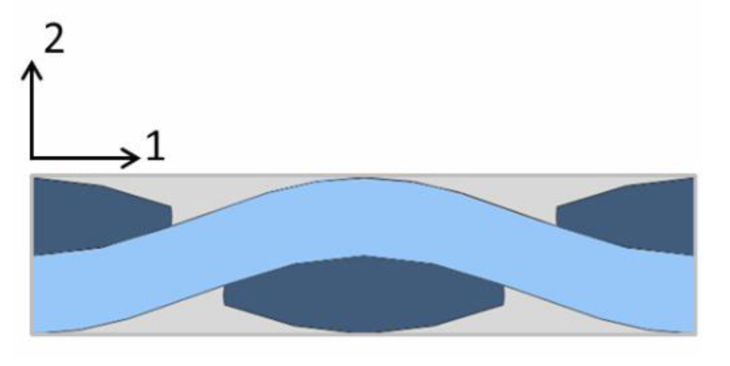
2.2. Model Geometry and Boundary Conditions

Previous studies [19,21] had shown that the damages inside the coatings are mainly caused by two factors: i) the mismatch of thermal expansion between layers; ii) the stress concentration caused by the rough interface between layers. It is necessary to establish a micro model considering the rough interface. A two-dimensional model was usually used to analyze the micro stress inside multilayer coatings. To simplify the model, sinusoidal, triangular, ellipse, and other geometric curves were often used to characterize the roughness of the interface. Here, the sinusoidal curve was used to model the interfaces inside the T/EBCs system. An RVE model with a length of one wavelength was established. The relationship between roughness and sinusoidal function is shown in Equation (1) [26].
{ R a = 2 π A R S m = λ
where Ra and Rsm refer to the amplitude and spacing parameters of roughness for the studied interfaces. They can be obtained through measurement. The definitions of surface roughness parameters and related information can be found in the literature [27]. A and λ refer to the amplitude and wavelength of the sine function, respectively.
Particularly, the thickness of TBC, EBC, and BC layers is 100 μm, and the thickness of the CMCs substrate is 1000 μm. The geometric model of an RVE is shown in Figure 2.
As shown in Figure 2, the following mechanical boundary conditions were applied to the analysis model. The bottom boundary of the CMCs substrate was fixed in the y-direction. The displacement in x-direction was fixed at a selected point on the bottom surface. The periodic boundary condition (PBC) of Equation (2) was applied to the left and right boundary of the coated system.
{ u x ( λ , y ) u x ( 0 , y ) = ε x λ u y ( λ , y ) u y ( 0 , y ) = 0
where ux and uy are displacements in the x- and y-directions, respectively. εx is the average strain in the x-direction of RVE. In this paper, the equation interaction in ABAQUS was used to carry out the PBC. A piece of Python code was written for this end.

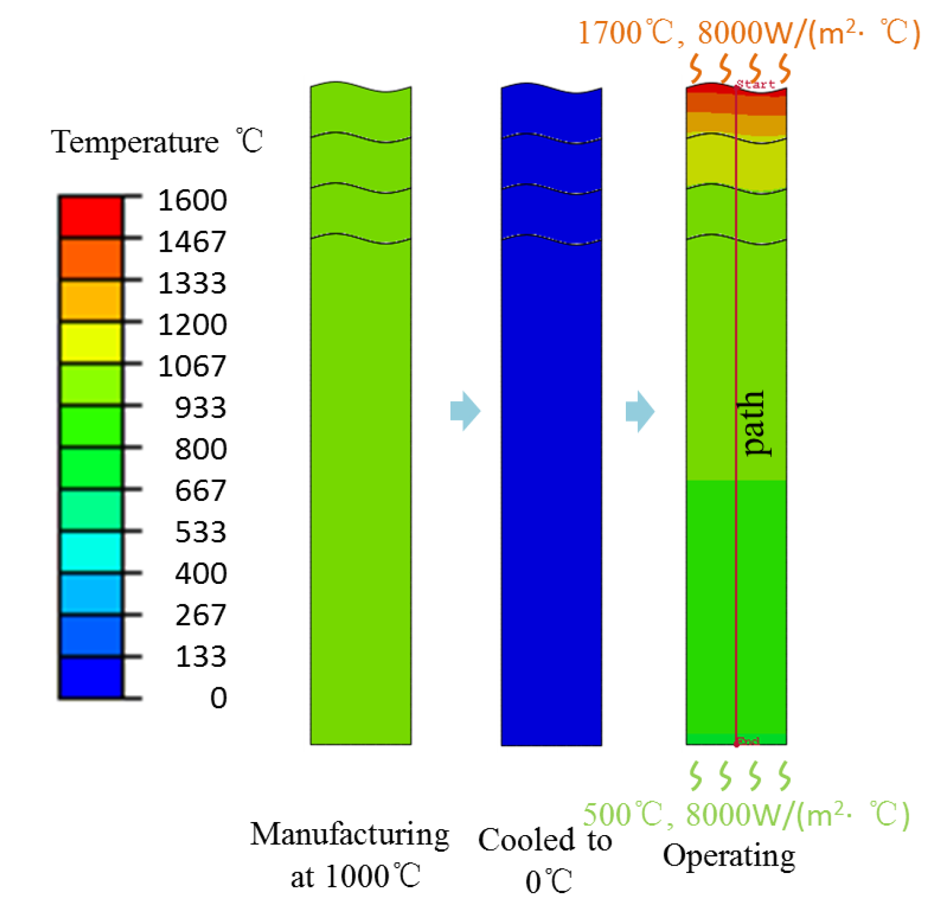
2.3. Simulation Procedure

As mentioned, the preparation process of EBCs is usually completed at a high temperature. Consequently, the thermal residual stress was introduced in the coatings which should be paid attention to. On the other hand, CMCs components are mainly used under high temperature such as combustion liner and turbine blades in aero-engine. Therefore, this paper attempted to investigate the thermal stress induced under the processing and operating conditions as shown in Figure 3.
(1)
Before the EBCs was deposited on the surface of CMCs at 1000 °C, all the constituents were assumed to be stress free;
(2)
After the preparation the coated system was cooled down to 0 °C, thermal residual stress is introduced;
(3)
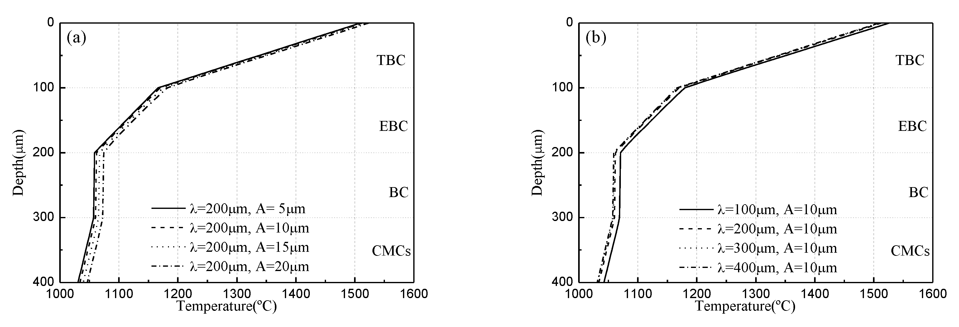
At last, the coated system was analyzed under a typical operating condition. The top surface was heated by 1700 °C high-temperature gas; the convective heat transfer coefficient is 8000 W/(m2·°C). While the bottom surface of CMCs was cooled by 500 °C air, and the convective heat transfer coefficient is 8000 W/(m2·°C).

2.4. Numerical Implementation

In the present work, the numerical procedure was performed using the commercial software ABAQUS 6.14. The two-dimensional geometry model mentioned earlier was generated using a piece of Python code which can control the interfacial roughness conveniently by several pre-defined parameters. The 4-node plane stress thermally coupled element (CPS4T) has been applied in the FE model as the heat conduction need to considered. A refined mesh through the coating layers was established while the mesh of CMCs substrate is coarse to save computing resources. In particular, the element size in coating layers is ~1 μm.
Two coupled temp-displacement steps were defined to simulate the studied procedure. Notably, a predefined temperature field were set at the initial step besides of the mechanical boundary conditions. For step 1, the temperature type boundary conditions were applied to cool the system. For step 2, the surface film conditions in interaction module were defined at both the top and bottom surface to simulate the operation thermal conditions. During the post-processing, the stress distributions along interface or depth were extracted using the path command as shown in Figure 3.

3. Results and Discussions

According to Equation (1), the amplitude and wavelength of the sinusoidal interface in RVE are corresponding to the amplitude and spacing characteristic of interface roughness, respectively. Therefore, the thermal stresses in RVEs with different wavelengths and amplitudes were simulated to analyze the effect of interface roughness on the stress distribution. According to the literature, the sinusoidal amplitude and wavelength were chosen in the range of 5~20 and 100~400 μm, respectively.

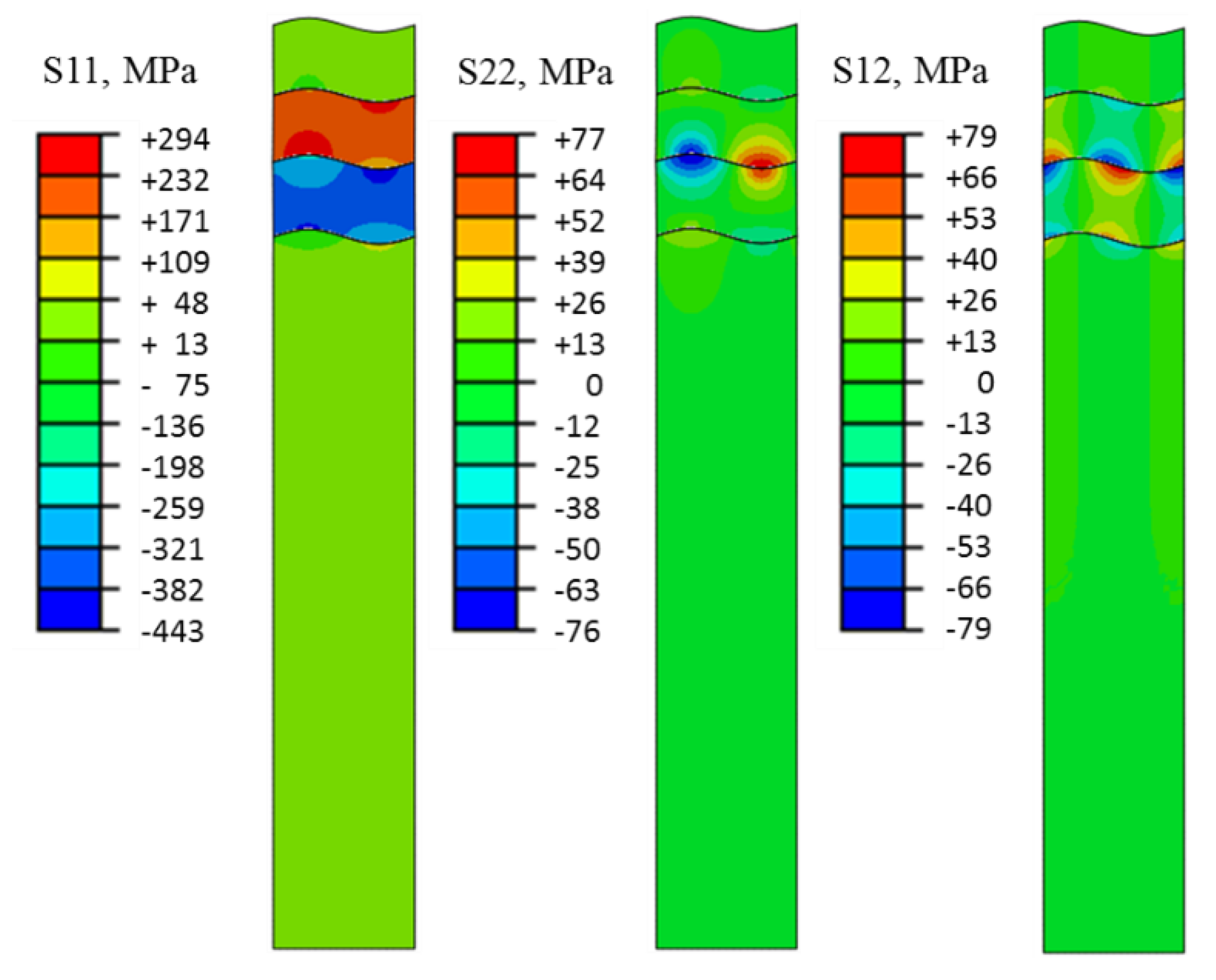
3.1. The Effect of Rough Interface on Thermal Residual Stress

Figure 4 shows the simulated residual stress of the coated system (roughness parameter λ = 200 μm, A = 10 μm) when it is cooled from 1000 to 0 °C. Due to the mismatch of thermal expansion between the different constituents of coatings and CMCs substrate. As seen, large thermal residual stress is caused during the preparation process. For all coating layers, the thermal residual stress along the longitudinal direction (S11) is larger than the other components. This is because there is no constraint in the through-thickness direction. But each layer is constrained by each other in the longitudinal direction as the PBC applied to the coated system. For the coefficients of thermal expansion of each layer, as shown in Table 1 and Table 2, it can be found that: EBC > CMCs > TBC > BC. Thus, the residual tensile stress occurs in the EBC layer while compressive stress occurs in the BC layer. For the thermal residual stress, the maximum tensile stress is 294 MPa and the maximum compressive stress is 443 MPa. As proved, the vertical crack in the EBC layer caused by thermal residual tensile stress (S11) is one of the most common damage modes during the cooling process. Besides, large shear stress (S12) and through-thickness stress (S22) are caused at the EBC/BC interface due to the significant difference of thermal expansion coefficients between the EBC layer and the BC layer. The EBC/BC interface is prone to delamination failure under thermal residual stress. The experimental research [19] found similar phenomena in a Si/mullite/Yb2SiO5 coating system deposited on SiC/SiC composites. No crack in the Si coating (BC layer) was found, while considerable microcracks were found in mullite (EBC layer) and Yb2SiO5 (TBC layer). Additionally, the cracking inside the mullite coating was the most serious.
It can also be seen from the figure that the rough interface would cause stress concentration at the peak and valley areas. The maximum tensile stress in the EBC layer and the maximum compressive stress in the BC layer appear at the areas near the peak or valley of the sinusoidal interfaces. At the same time, the through-thickness stress (S22) and shear stress (S12) of each layer also reach the maximum values near the peak or valley. The extreme values of S22 and S12 in the entire coated system appear at the interface between the EBC layer and the BC layer.
To figure out the effect of rough interface on the distribution of thermal residual stress, the preparation processes of the coating system with different rough interfaces were simulated. Firstly, the longitudinal residual stress S11 along the depth was extracted and compared. The distributions of S11 along two different paths, at the peak and valley of the sinusoidal curve, were plotted in Figure 5. As seen, the magnitudes of thermal residual stress in the TBC layer and CMCs substrate are at a comparatively low level. While large thermal residual stress occurs in the EBC layer and BC layer. Comparing Figure 5a,b, it can be found that the distribution of thermal residual stress along the depth direction at the valley and trough is very different. Taking EBC as an example, S11 increases with the depth at the peak and decreases at the valley. In theory, the average stress of each layer is almost the same for coatings with different interfacial roughness. However, the fluctuation ranges of stress increase with the amplitude of the sinusoidal interface. Comparing Figure 5c,d, it is found that the fluctuation range of S11 in coating layers decreases with the wavelength of the sinusoidal interface for the same amplitude.
As discussed in Figure 4, stress concentration was caused near the EBC/BC interface which is the prone area of delamination damage. The variations of normal stress along the longitudinal direction at the EBC/BC interface with different interfacial roughness were plotted in Figure 6. As seen, the maximum normal stress at the EBC/BC interface appears in the middle for the sinusoidal interface. Figure 6a shows the effect of the amplitude of interface roughness on the stress distribution. For the same wavelength, the fluctuation ranges of normal thermal residual stress at the EBC/BC interface increases with the amplitude. The maximum normal residual stress increases from 10 MPa for A = 5 μm to 130 MPa for A = 20 μm, and the minimum normal residual stress increases from 0.2 MPa for A = 5 μm to 22 MPa for A = 20 μm. Figure 6b shows the effect of wavelength of interface roughness on stress distribution. For the same amplitude, the fluctuation ranges of normal thermal residual stress decrease with the wavelength. When A = 10 μm, the maximum normal thermal residual stress decreases from 90 MPa for λ = 100 μm to 10 MPa for λ = 400 μm. Meanwhile, the minimum normal residual stress decreases from 30 MPa for λ = 100 μm to 2 MPa for λ = 400 μm. It can be seen that the roughness of the interface has a significant effect on the normal thermal residual stress at the EBC/BC interface.
The variation of tangential thermal residual stress along the longitudinal direction at the EBC/BC interface with different roughness is plotted in Figure 7. It can be seen that for the sinusoidal interface, the maximum and minimum tangential residual stress of the EBC/BC interface appears at the end and middle of wavelength, respectively. The absolute values of maximum and minimum tangential stress are approximately equal. Figure 7a shows the effect of the amplitude of the rough interface on the stress distribution. For the same wavelength λ = 200 μm, the fluctuation ranges of tangential thermal residual stress at the EBC/BC interface increases with the amplitude of roughness. The range of tangential thermal residual stress increases from ± 70 MPa for A = 5 μm to ± 250 MPa for A = 20 μm. Figure 7b shows the effect of the wavelength of the rough interface on stress distribution. With the same amplitude, the fluctuation ranges of tangential thermal residual stress decrease with the wavelength. When A = 10 μm, the maximum tangential thermal residual stress range decreases from ±240 MPa for λ = 100 μm to ± 90 MPa for λ = 400 μm. It can be seen that the rough interface has a significant effect on the tangential thermal residual stress at the EBC/BC interface.

3.2. The Effect of Rough Interface On Thermal Stress under Service Conditions

The CMCs components are usually designed to service under a large thermal gradient. Here, the thermal stress distribution of the coated system under a thermal gradient is simulated. Under the given simulation conditions, the variation of temperature with depth in the coated system was obtained. It can be seen from Figure 8 that the temperature at the top surface of the TBC layer reaches above 1500 °C, and the temperature at the bottom of the TBC layer drops to less than 1200 °C. The temperature at EBC/BC interface drops to less than 1100 °C and the temperature at the top surface of CMCs decreases slightly. It can be seen that the TBC layer works well as a thermal barrier. Figure 8a,b also compare the effects of roughness amplitude and wavelength on temperature variation. It can be seen that the interfacial roughness has little effect on the temperature distribution which can be ignored.
Figure 9 shows the predicted stress profile of CMCs coating (roughness parameter λ = 200 μm, A = 10 μm) under typical service conditions. Compared with the thermal residual stress shown in Figure 4, it can be seen that the thermal residual stress of each layer has been eliminated to a certain extent due to the service condition of high temperature. The maximum stress along the longitudinal direction (S11) is 133 MPa and the minimum is −231 MPa, which is greatly reduced compared with the thermal residual stress caused during processing. The positions of the maximum tensile stress and compressive stress are almost the same as those of the thermal residual stress. The biggest difference is that the distribution of thermal stress in the TBC layer is more uneven, and the obvious stress concentration appears on its surface. This is because the TBC layer bears a large thermal gradient, which leads to a large thermal stress. The concentration of thermal stress on the coating surface will lead to a large number of surface cracks, which is consistent with the results observed in relevant experimental studies [28].
Figure 10 shows the variation of Mises stress along the length direction of the TBC surface under typical service conditions of CMCs coating. It can be seen that the minimum Mises stress occurs at the valley while the maximum stress occurs at the peak. Figure 10a shows the influence of the amplitude of surface roughness on the thermal stress distribution. For the same wavelength, the larger the amplitude is, the larger magnitude and range the Mises stress are. The maximum Mises stress on TBC surface increases from 190 MPa for A = 5 μm to 280 MPa at A = 20 μm when λ = 200 μm. Figure 10b shows the effect of wavelength of surface roughness on thermal stress distribution. As seen, the higher the wavelength is, the smaller the stress level and range of Mises stress on the surface of the coating is for the same amplitude.

3.3. Analysis of Possible Failure Mode

The stress distribution plays an important role in determining the failure mode. As calculated, it can be recognized that the residual tensile stress was induced in the EBC layer while the residual compressive stress was induced in the BC layer during the processing of coatings. This means a large stress mismatch will be induced between these two adjacent coating layers. Moreover, the rough interface will enlarge the mismatch. As shown in Figure 11a, the delamination cracks would probably initiate at location A, B and C. Whether delamination will occur or not is determined by the interfacial strength of the related interface. And where the delamination will initiate can be captured by the stress concentrations. These dangerous regions are caused by the microstructure, i.e., the rough interface here. It can be seen that the probability of delamination between EBC and BC layers will increase with the interfacial roughness. Similarly, the delamination between EBC and BC layers prefer to initiate at the transition between raised and depression areas.
Under the typical service conditions with large temperature gradient, the distribution of thermal stress is quite different to the residual stress. As discussed, the thermal residual stress in the T/EBC coating system can be eliminated to some extent. However, large stress concentrations would be induced at coating surface at the same time. Indeed, the most regions of TBC layer were under compression but uneven stress distribution were caused by the coarse surface. The compressive stress can also cause crack initiations as shown in Figure 11b. The most dangerous regions were denoted as D, E and F in the figure. Cracks will initiate at these regions when the maximum stress reaches the strength of the TBC layer. The cracking direction will be determined by the local stress state. It should be noted that the crack patterns may be very different as the stress state will vary with the location as the surface is uneven.

4. Conclusions

The residual stress distribution in the EBCs, induced by thermal expansion mismatch, is found to vary with the rough interface as well as in-depth. For the T/EBC coating system deposited on SiC/SiC composite, the rough interface does not alter the temperature distribution with the depth. The stress profile indicates that the stress in the coatings is affected by the rough interface. The results are as follows:
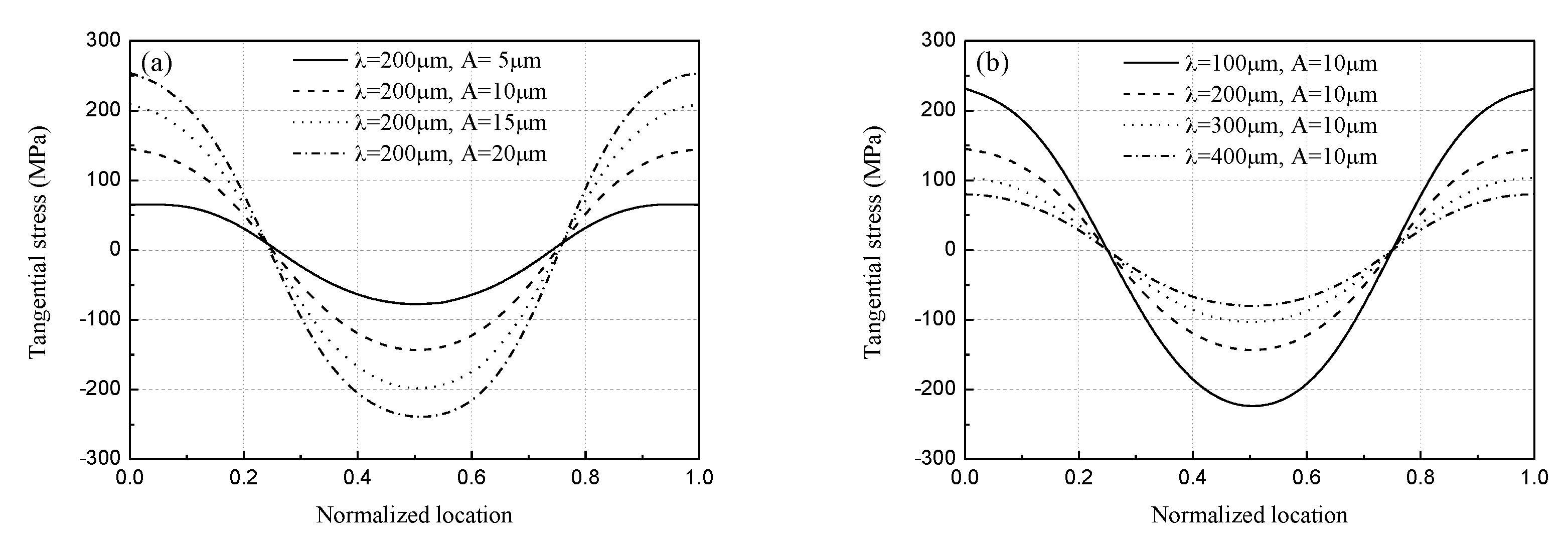
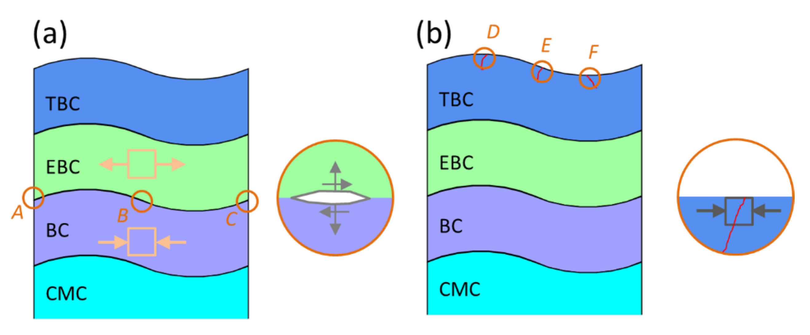
  • During the processing, considerable thermal residual stress is induced in coatings. Large in-plane and through-thickness residual stress may cause vertical cracks in the EBC layer and delamination cracks at the interface between the EBC and BC layer. The rough interface plays an important role in the distribution of thermal residual stress. Stress concentration occurs near the peak and valley of the rough interface. The range of stress variation increases with the amplitude while decreases with the wavelength.
  • Under the typical service conditions for SiC/SiC composites, the thermal residual stress in the T/EBC coating system can be eliminated to some extent. However, large thermal stress may be induced at the surface layer of TBC due to the thermal gradient. This stress tends to cause surface cracks. Thus, the surface roughness has a significant impact on the thermal stress distribution. The magnitude and range of thermal stress increase with the roughness level.

Author Contributions

Conceptualization, G.F. and J.R.; methodology, G.F. and X.G.; software, J.R.; validation, G.F. and J.S.; writing—original draft preparation, G.F.; writing—review and editing, Y.S.; visualization, J.S.; project administration, X.G.; funding acquisition, Y.S. All authors have read and agreed to the published version of the manuscript.

Funding

This work was supported by the National Science and Technology Major Project, Grant No. 2017-IV-0005-0042; the Natural Science Foundation of universities in Anhui, Grant No. KJ2018A0057; Key Laboratory of Aero-engine Thermal Environment and Structure, Ministry of Industry and Information Technology, Grant No. CEPE2018006; and the National Natural Science Foundation of China, Grant No. 11972183.

Conflicts of Interest

The authors declare no conflict of interest.

References

  1. Xu, Y.; Ren, S.; Zhang, W.; Wu, Z.; Gong, W.; Li, H. Study of thermal buckling behavior of plain woven C/SiC composite plate using digital image correlation technique and finite element simulation. Thin Wall Struct. 2018, 131, 385–392. [Google Scholar] [CrossRef]
  2. Li, J.; Martin, E.; Leguillon, D.; Dupin, C. A finite fracture model for the analysis of multi-cracking in woven ceramic matrix composites. Compos. Part B Eng. 2018, 139, 75–83. [Google Scholar] [CrossRef] [Green Version]
  3. Dong, X.; Shin, Y.C. Predictions of thermal conductivity and degradation of irradiated SiC/SiC composites by materials-genome-based multiscale modeling. J. Nucl. Mater. 2018, 512, 268–275. [Google Scholar] [CrossRef]
  4. Fang, G.; Li, L.; Gao, X.; Song, Y. Finite Element Analysis of the Crack Deflection in Fiber Reinforced Ceramic Matrix Composites with Multilayer Interphase Using Virtual Crack Closure Technique. Appl. Compos. Mater. 2020, 27, 307–320. [Google Scholar]
  5. Song, Y.; Gao, X.; Sun, Z. Progress on Fatigue Hysteresis Mechanisms and Models of Aero-engine Ceramic Matrix Composites. J. Nanjing Univ. Aeronaut. Astronaut. 2019, 51, 417–426. [Google Scholar]
  6. Xu, J.; Sarin, V.K.; Dixit, S.; Basu, S.N. Stability of interfaces in hybrid EBC/TBC coatings for Si-based ceramics in corrosive environments. Int. J. Refract. Met. Hard Mater. 2015, 49, 339–349. [Google Scholar] [CrossRef]
  7. Lee, K.; Roode, M.; Kashyap, T. Environmental Barrier Coatings for Ceramic Matrix Composites-an Overview; GRC-E-DAA-TN38835; NASA: Washington, DC, USA, 2017.
  8. Białas, M. Finite element analysis of stress distribution in thermal barrier coatings. Surf. Coat. Technol. 2008, 202, 6002–6010. [Google Scholar] [CrossRef]
  9. Wang, L.; Wang, Y.; Sun, X.G.; He, J.Q.; Pan, Z.Y.; Wang, C.H. Finite element simulation of residual stress of double-ceramic-layer La2Zr2O7/8YSZ thermal barrier coatings using birth and death element technique. Comput. Mater. Sci. 2012, 53, 117–127. [Google Scholar] [CrossRef]
  10. Wang, L.; Wang, Y.; Zhang, W.Q.; Sun, X.G.; He, J.Q.; Pan, Z.Y.; Wang, C.H. Finite element simulation of stress distribution and development in 8YSZ and double-ceramic-layer La2Zr2O7/8YSZ thermal barrier coatings during thermal shock. Appl. Surf. Sci. 2012, 258, 3540–3551. [Google Scholar]
  11. Yu, Q.M.; Cen, L.; Wang, Y. Numerical study of residual stress and crack nucleation in thermal barrier coating system with plane model. Ceram. Int. 2018, 44, 5116–5123. [Google Scholar] [CrossRef]
  12. Bhattacharyya, A.; Maurice, D. Residual stresses in functionally graded thermal barrier coatings. Mech. Mater. 2019, 129, 50–56. [Google Scholar] [CrossRef]
  13. Nayebpashaee, N.; Seyedein, S.H.; Aboutalebi, M.R.; Sarpoolaky, H.; Hadavi, S.M.M. Finite element simulation of residual stress and failure mechanism in plasma sprayed thermal barrier coatings using actual microstructure as the representative volume. Surf. Coat. Technol. 2016, 291, 103–114. [Google Scholar] [CrossRef]
  14. Rezvani Rad, M.; Farrahi, G.H.; Azadi, M.; Ghodrati, M. Stress analysis of thermal barrier coating system subjected to out-of-phase thermo-mechanical loadings considering roughness and porosity effect. Surf. Coat. Technol. 2015, 262, 77–86. [Google Scholar] [CrossRef]
  15. Moridi, A.; Azadi, M.; Farrahi, G.H. Thermo-mechanical stress analysis of thermal barrier coating system considering thickness and roughness effects. Surf. Coat. Technol. 2014, 243, 91–99. [Google Scholar] [CrossRef]
  16. Al Nasiri, N.; Patra, N.; Pezoldt, M.; Colas, J.; Lee, W.E. Investigation of a single-layer EBC deposited on SiC/SiC CMCs: Processing and corrosion behaviour in high-temperature steam. J. Eur. Ceram. Soc. 2019, 39, 2703–2711. [Google Scholar] [CrossRef]
  17. Appleby, M.P.; Zhu, D.; Morscher, G.N. Mechanical properties and real-time damage evaluations of environmental barrier coated SiC/SiC CMCs subjected to tensile loading under thermal gradients. Surf. Coat. Technol. 2015, 284, 318–326. [Google Scholar] [CrossRef] [Green Version]
  18. Lee, K.N.; Eldridge, J.I.; Robinson, R.C. Residual Stresses and Their Effects on the Durability of Environmental Barrier Coatings for SiC Ceramics. J. Am. Ceram. Soc. 2005, 88, 3483–3488. [Google Scholar] [CrossRef]
  19. Zhang, X.; Zhou, K.; Liu, M.; Deng, C.; Niu, S.; Xu, S. Preparation of Si/Mullite/Yb2SiO5 Environment Barrier Coating (EBC) by Plasma Spray-Physical Vapor Deposition (PS-PVD). J. Inorg. Mater. 2018, 33, 325–330. [Google Scholar]
  20. Abdul-Aziz, A.; Bhatt, R.T. Modeling of thermal residual stress in environmental barrier coated fiber reinforced ceramic matrix composites. J. Compos. Mater. 2012, 46, 1211–1218. [Google Scholar] [CrossRef]
  21. Heveran, C.M.; Xu, J.; Sarin, V.K.; Basu, S.N. Simulation of stresses in TBC–EBC coating systems for ceramic components in gas turbines. Surf. Coat. Technol. 2013, 235, 354–360. [Google Scholar] [CrossRef]
  22. Song, Y.; Zhuan, X.; Wang, T.J.; Chen, X. Thermal Stress in Fabrication of Thermal Barrier Coatings. J. Therm. Stresses 2014, 37, 1390–1415. [Google Scholar] [CrossRef]
  23. Lee, K.N.; Fox, D.S.; Bansal, N.P. Rare earth silicate environmental barrier coatings for SiC/SiC composites and Si3N4 ceramics. J. Eur. Ceram. Soc. 2005, 25, 1705–1715. [Google Scholar] [CrossRef]
  24. Robertson, A.L.; Solá, F.; Zhu, D.; Salem, J.; White, K.W. Microscale fracture mechanisms of HfO2-Si environmental barrier coatings. J. Eur. Ceram. Soc. 2019, 39, 2409–2418. [Google Scholar] [CrossRef]
  25. Shen, X.; Qiao, Y.; Dong, S.; Liu, X.; Gong, L. Thermal Load Test Method and Numerical Calculation for Ceramic Matrix Composite Turbine Guide Vane. Appl. Compos. Mater. 2019, 26, 553–573. [Google Scholar] [CrossRef]
  26. Eriksson, R.; Sjöström, S.; Brodin, H.; Johansson, S.; Östergren, L.; Li, X.-H. TBC bond coat–top coat interface roughness: Influence on fatigue life and modelling aspects. Surf. Coat. Technol. 2013, 236, 230–238. [Google Scholar] [CrossRef] [Green Version]
  27. Gadelmawla, E.S.; Koura, M.M.; Maksoud, T.M.A.; Elewa, I.M.; Soliman, H.H. Roughness parameters. J. Mater. Process. Technol. 2002, 123, 133–145. [Google Scholar] [CrossRef]
  28. Zhu, D.; Nemeth, N.N. Environmental Barrier Coating Fracture, Fatigue and High-Heat-Flux Durability Modeling and Stochastic Progressive Damage Simulation; GRC-E-DAA-TN48415; NASA: Washington, DC, USA, 2017.
Figure 1. Microstructure of 2D woven SiC/SiC composites.
Coatings 10 00947 g001
Figure 2. Geometric model and mechanical boundary conditions of CMCs coatings.
Coatings 10 00947 g002
Figure 3. Temperature field of during the simulation process for CMCs coatings.
Coatings 10 00947 g003
Figure 4. The contours of thermal residual stress in coated CMCs after processing.
Coatings 10 00947 g004
Figure 5. Variation of thermal residual stress S11 in CMCs coatings along the depth direction: the effect of amplitude at (a) peak path and (b) valley path; the effect of wavelength at (c) peak path and (d) valley path.
Coatings 10 00947 g005
Figure 6. Variations of normal thermal residual stress along the EBC/BC interface of CMCs coatings with different (a) amplitude; (b) wavelength.
Coatings 10 00947 g006
Figure 7. Variations of tangential thermal residual stress along the EBC/BC interface of CMCs coatings with different (a) amplitude; (b) wavelength.
Coatings 10 00947 g007
Figure 8. Variation of temperature versus depth of CMCs coatings under service conditions with different (a) amplitude; (b) wavelength.
Coatings 10 00947 g008
Figure 9. The thermal stress contours of CMCs coating under typical service conditions.
Coatings 10 00947 g009
Figure 10. Mises stress along the length of the surface of CMCs coatings with different (a) amplitude; (b) wavelength.
Coatings 10 00947 g010
Figure 11. Analysis of possible failure mode for the investigated coatings induced by (a) thermal residual stress and (b) operating thermal stress.
Coatings 10 00947 g011
Table 1. Thermal-mechanical properties of the constituents in composites coating.
ConstituentsE/GPavk/(W·m−1·K−1)α/(×10−6K−1)
TBC (La2Zr2O7)630.250.874.25
EBC (Yb2Si2O7)1500.283.55.5
BC (Si)970.2114.233.5
Table 2. Thermal-mechanical properties of 2D woven SiC/SiC composites.
E1/GPaE2/GPav12G12/GPak1/(W·m−1·K−1)k2/(W·m−1·K−1)α1/(×10−6K−1)α2/(×10−6K−1)
238.3781.400.2096.9212.18.834.363.80

