Abstract
Coatings in the Ta-Zr-Si-B-C-N system were produced by magnetron sputtering of a TaSi2-Ta3B4-(Ta,Zr)B2 ceramic target in the Ar medium and Ar-N2 and Ar-C2H4 gas mixtures. The structure and composition of coatings were studied using scanning electron microscopy, glow discharge optical emission spectroscopy, energy-dispersion spectroscopy, and X-ray diffraction. Mechanical and tribological properties of coatings were determined using nanoindentation and pin-on-disk tests using 100Cr6 and Al2O3 balls. The oxidation resistance of coatings was evaluated by microscopy and X-ray diffraction after annealing in air at temperatures up to 1200 °C. The reactively-deposited coatings containing from 30% to 40% nitrogen or carbon have the highest hardness up to 29 GPa and elastic recovery up to 78%. Additionally, coatings with a high carbon content demonstrated a low coefficient of friction of 0.2 and no visible signs of wear when tested against 100Cr6 ball. All coatings except for the non-reactive ones can resist oxidation up to a temperature of 1200 °C thanks to the formation of a protective film based on Ta2O5 and SiO2 on their surface. Coatings deposited in Ar-N2 and Ar-C2H4 demonstrated superior resistance to thermal cycling in conditions 20-T−20 °C (where T = 200–1000 °C). The present article compares the structure and properties of reactive and “standard-inert atmosphere” deposited coatings to develop recommendations for optimizing the composition.
1. Introduction
One of the prospective avenues of surface engineering is the deposition of hard, wear-, and oxidation-resistant transitional-metal based coatings for high-performance metal machining instruments by arc-evaporation and magnetron sputtering of composite targets [1,2,3,4,5]. Additionally, such coatings can be employed for heavy-duty friction pairs, high-temperature sensors, and resistive elements, critical parts for the aerospace industry. Tantalum disilicide (TaSi2) is often the material of choice for the engineering of coatings thanks to its high hardness (10–13 GPa) and refractoriness (2200 °C), low thermal expansion coefficient (8.8 × 10⁻⁶ °C−1), high strength at temperatures above 1000 °C, and oxidation resistance (up to 1700 °C) [6,7,8].
TaSi2-based coatings can be produced by chemical vapor deposition and subsequent diffusion saturation [9,10], plasma spraying [11], sintering [12], slurry impregnation [13], electron beam evaporation [14], low-pressure chemical vapor deposition [15], diode or high-frequency sputtering [16], magnetron sputtering [17,18], and double-cathode sputtering [19]. In the case of surface engineering of metal-machining tools, chemical (CVD) and physical vapor deposition (PVD) techniques outperform other methods owing to the unrivaled capability to retain blade geometry, high quality, and homogeneity of the coating, as well as the general flexibility and possibility to fine-tune the properties of coatings.
The functional properties of TaSi2-based coatings can be enhanced by alloying. The addition of Al increases the adhesion strength of TaSi2 coatings by ~28%, despite an 8% decrease in hardness and a ~12% decrease in elastic modulus in [19,20]. Additionally, Al decreases the corrosion current density in Ta(Si1-xAlx)2 coatings from 7.08 × 10⁻⁶ to 3.05 × 10⁻⁶ A·cm−2 [20]. Alloying of Ta-Si coatings by Zr and Ti improved the coatings’ hardness (12–16 GPa) and corrosion resistance [21], whereas alloying by Ni produced amorphous coatings stable up to 900 °C for microelectronic applications [22]. Alloying by nitrogen and carbon is another promising avenue for enhancing the properties of TaSi2-based coatings. Such coatings were deposited by magnetron sputtering of composite TaSi2-SiC targets in the atmosphere with varied nitrogen content, resulting in hardness up to 26 GPa, friction coefficient below 0.3 at temperatures above 600 °C, and heat resistance up to 800 °C [23]. The introduction of Si3N4 into the TaSi2 coatings allows for a substantial increase in oxidation resistance [24]. The Ta-Si-N coatings have high thermal stability up to 900 °C [25]. Moreover, Ta-Si-N coatings possess good diffusion barrier properties [26] and are used to prolongate the lifespan of high-speed steel cutting tools [27] and glass forms [28]. Increased Si content endows the Ta-Si-N coatings with oxidation resistance up to 1300 °C [29]. A similar effect is produced by boron alloying, as it promotes the formation of borosilicate glass in the oxide layer, thereby reducing the viscosity and increasing the protective properties of the oxide [30].
The aim of this work is the comparative study of the structures and properties of Ta-Zr-Si-B-(C,N) coatings deposited by magnetron sputtering of composite target TaSi2-Ta3B4-(Ta,Zr)B2 in inert (Ar) and reactive atmospheres (Ar-N2 and Ar-C2H4).
2. Materials and Methods
The coatings were deposited by magnetron sputtering in the direct current mode. The sputtered composite target TaZrSiB—with element composition of 70.8 wt.% Ta, 18.6 wt.% Si, 7.4 wt.% Zr, and 2.9 wt.% B, and phase composition of TaSi2-Ta3B4-(Ta,Zr)B2, 120 mm diameter, and 6 mm thickness—was produced by hot pressing on DSP-515 SA installation (“Dr. Fritsch”, Germany). The feedstock powders for hot pressing were fabricated by the ball-milling of the combustion products of a reactive mixture of Ta, Zr, Si, and B. The details of the combustion synthesis protocol can be found elsewhere [31].
VK-100-1 grade alumina plates (99.7% Al2O3, JSC Policor, Kineshma, Ivanovo region, Russia), and alumina discs VOK (VNIITS, Russia) and VT-1-0-grade (OAO Conmet, Moscow, Russia) were used as the substrates. Before deposition, the substrates were ultrasonically cleaned in isopropanol at a frequency of 22 kHz for 5 min using the UZDN-2T installation (JSC «UKRROSPRIBOR», Ukraine). Additional cleaning via ion etching was performed right before the coating deposition using the slit-type ion source (Ar+ ions, 2 keV) for 20 min. The coatings were deposited under the following conditions: 80 mm distance between the substrate and the target, 10−3 Pa residual pressure, and 0.1–0.2 Pa working pressure in the vacuum chamber. Ar (99.9995%) was used as the working gas, as well as its mixtures with N2 (99,999%) and C2H4 (99.95%). The gas flow rate (Table 1) was controlled by the gas supply system ELTOCHPRIBOR, LTD (Moscow, Russia). The constant current (1 kW power) was supplied to the magnetron using Pinnacle+ source (Advanced Energy, Fort Collins, CO, USA) during the whole deposition duration (40 min). Experiments were conducted without applying a bias voltage to the substrate. The schematics of the installation are given in the work [32].

Table 1.
Composition, thickness, and deposition rate of coatings.
The elemental composition and structure of coatings were studied using scanning electron microscopy (SEM) using the S-3400 microscope (Hitachi, Tokyo, Japan) equipped with the energy dispersive spectroscopy add-on (EDS) Noran-7 Thermo. X-ray diffraction analysis (XRD) was performed on a D2 Phaser Bruker diffractometer using CuKα radiation. Elemental distribution profiles across the thickness of the coating were studied by glow discharge optical emission spectroscopy (GDOES) using Profiler 2 installation (“Horiba Jobin Yvon”, Longjumeau, France). Studies of the fine structure were performed using a high-resolution transmission electron microscope (HR TEM) JEM-2100 Jeol. The foils for HR TEM were prepared using the ion-beam etching unit PIPS II System (Gatan, Pleasanton, CA, USA) and FIB (FEI Quanta 200 3D FIB instrument, Hillsboro, OR, USA). The coatings’ mechanical properties were tested at a load of 2 mN on a nano-hardness tester (CSM Instruments, Peuseux, Switzerland) equipped with a Berkovich indenter. The tribological performance of the coatings was tested on an automated friction machine Tribometer (CSM Instruments) using a «pin-on-disc» scheme and a normal load of 1 N. Balls (d = 6 mm) made of alumina (hardness 19 GPa) and 100Cr6 grade steel (hardness of 8 GPa) were used as the counterparts for tribological experiments. Wear tracks were studied using an optical profiler Wyko-1100NT (Veeco, Plainview, NY, USA). To assess the coatings oxidation resistance, step-by-step annealing was performed in the air in a muffle furnace SNOL 7.2/1200 (Umega, Ukmerge, Lithuania) with a step of 200 °C, a maximum temperature of 1200 °C, and 1 h exposure. The specimens were inserted into a furnace heated to a given temperature T, dwelled during 1 h in the air, and afterward ejected from the furnace and cooled to 20 °C. The temperature was increased using 200 °C steps, and 1000 °C was the highest temperature the coatings could endure for 1 h without complete oxidation. At 1200 °C, all coatings were completely oxidized after 1 h long experiment; therefore, the oxidation duration for the test at this temperature was decreased to 10 min. Annealed coatings were studied by SEM and EDS. A more detailed description of the employed methods and equipment can be found elsewhere [33].
3. Results
The GDOES data (Table 1) were used to quantify the thickness of the coatings and assess the homogeneity of the elemental distribution within the coatings. The elemental profiles show all the main elements that make up the target, such as tantalum, zirconium, silicon, and boron. In coatings applied in environments containing nitrogen and ethylene, there is also a signal from nitrogen and carbon, respectively (Figure 1). The emergence of Ti lines signifies the boundaries between the coatings and Ti-alloys substrate and allows for an assessment of the coatings’ thickness (6.6 μm in the case of coating 3 and 5.8 μm in the case of coating 5).
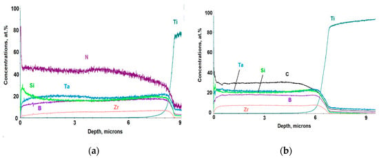
Figure 1.
Typical glow discharge optical emission spectroscopy (GDOES) profiles of coatings 3 (10 sccm N2) (a) and 5 (10 sccm C2H4) (b).
According to the GDOES data, all elements were evenly distributed across the thickness of coatings. The concentration of oxygen impurities was below 1 at.%. The minor oxygen contamination resulted from the presence of corresponding impurities both in the ceramic target and in the working gas. The depth-averaged coating composition is shown in Table 1.
The coatings deposited in argon contained 47.6 at.% of metals and 52.4 at.% of non-metals, so the metal-to-nonmetal species ratio was close to 1. The increased flow of reactive gases resulted in higher nitrogen or carbon content in coatings and a decreased concentration of elements inherited from the target (except for Zr). The maximum N and C concentrations (42.4 and 30.3 at.%, respectively) were achieved at 10 sccm of N2 and C2H4, correspondingly.
Non-reactive deposited coating 1 had a dense structure with pronounced columnar grains, which is typical for ion-plasma deposited coatings [34,35] (Figure 2a).
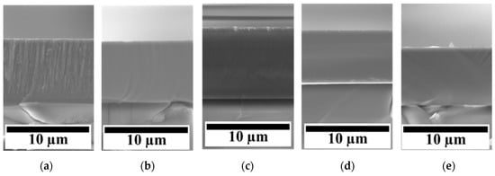
Figure 2.
Cross-section scanning electron microscopy (SEM) images of as-deposited coatings 1 (Ar) (a), 2 (5 sccm N2) (b), 3 (10 sccm N2) (c), 4 (5 sccm C2H4) (d), and 5 (10 sccm C2H4) (e).
A similar columnar structure was reported for TaSi2-based coatings in [18,28]. When N2 (coatings 2 and 3) or C2H4 (coatings 4 and 5) were added to the working gas, the columnar structure became less pronounced or completely disappeared. The coatings produced by reactive sputtering featured a nearly perfect, defect-free structure.
The coatings’ thickness, depending on the deposition modes, ranged from 6.3 to 8.0 microns (Table 1). The introduction of a minor amount of nitrogen (coating 2) had no significant effects on the growth rate (180 nm/min). With an increase in nitrogen concentration (coating 3), a boost in the growth rate of up to 200 nm/min was observed. When carbon-containing gas was added to the sputtering atmosphere, the growth rate decreased to 157 nm/min (coating 4) or 175 nm/min (coating 5).
The XRD patterns and HRTEM-imaged structure of the coatings 1–5 are shown in Figure 3.
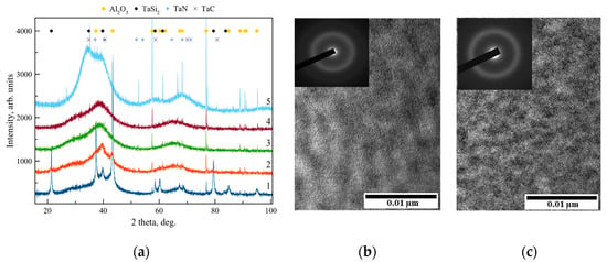
Figure 3.
X-ray diffraction analysis (XRD) patterns of coatings 1(Ar), 2 (5 sccm N2), 3 (10 sccm N2), 4 (5 sccm C2H4), and 5 (10 sccm C2H4) deposited onto alumina substrate (a); selected area electron diffraction (SAED) and high-resolution transmission electron microscope (HR TEM) image of coatings 3 (10 sccm N2) (b) and 5 (10 sccm C2H4) (c).
A signal from the substrate of Al2O3 (JCPDS 88-0107 card) was detected for all samples. The XRD pattern for coating 1 contained peaks associated with reflections from planes (100), (102), (111), (210), (203), (220), and (115) of the h-TaSi2 hexagonal phase (JCPDS 89-2941), similar to [36]. The size of the h-TaSi2 crystallites determined by the Scherrer formula for the coating obtained in Ar was approximately 11 nm. The transition to reactive sputtering (in Ar-N2 and Ar-C2H4) resulted in a considerable structural refinement of the coatings. The most intense peak in the 2Θ = 25–45° range for coatings obtained in Ar-N2 can be attributed to the Ta-N bonds in the coating (FCC-TaN, JCPDS 89-5198), which agrees with the previously obtained XRD results for Ta-Si-N coatings deposited at a different N2/(N2 + Ar) ratio [37]. The crystallite size of the phase h-TaSi2 for coatings 2 and 3 produced by reactive sputtering was evaluated according to the most distinct lines. Coating 2, deposited at a flow rate of 5 sccm N2, had a grain size of the h-TaSi2 phase equal to ~6 nm. As the N2 flow rate increased, the crystallite size decreased to 4.5 nm. Coatings 4 and 5 deposited in the Ar + C2H4 atmosphere show broad peaks on XRD patterns at 2Θ from 30° to 45°. Their position can be explained by the presence of Ta-Si and Ta-C bonds (TaC, JCPDS 89-3831). The introduction of nitrogen and carbon into the coatings resulted in grain refinement of h-TaSi2 phase to 3–6 nm according to HR TEM и selected area electron diffraction (SAED) data (Figure 3b,c) The sizes of the h-TaSi2 phase crystallites for coatings deposited at 5 and 10 sccm C2H4 flow rates were equal to 3.5 and 3.0 nm, respectively. The TEM data correlated well with the results of XRD.
The mechanical properties of coatings, such as hardness (H), elastic modulus (E), elastic recovery (W), plasticity index (H/E), and the resistance to plastic deformation (H3/E2) and compressive stress (σ), are shown in Table 2.

Table 2.
Mechanical and chemical properties of coatings.
Coating 1 deposited in Ar demonstrated H = 12.5 GPa, E = 208 GPa, and W = 43.4%. The transition to reactive deposition at a flow rate of 5 sccm N2 resulted in an increase in H by 46% as well as an increase in E and W by 12% and 32%, respectively. When the N2 flow rate was increased to 10 sccm, H rose further to 29.2 GPa, while E and W increased to 279 GPa and 77.9%, respectively. This effect might be related to the formation of tantalum nitride phase [38,39] or structure refinement [40]. The introduction of carbon atoms into the coatings also resulted in an increase of mechanical properties. Coating 4 deposited at a flow rate of 5 sccm C2H4 had H = 21.3 GPa, E = 267 GPa, and W = 62.4%, which is 70%, 28%, and 44% higher, respectively, than the values obtained for the non-reactive sample. Coating 5 demonstrated hardness H = 28.3 GPa, Young’s modulus E = 288 GPa, and elastic recovery W = 76.4%. The mechanical properties of coatings increased at higher carbon concentrations, similar to the results obtained in [41,42]. The increase in mechanical properties can be partially attributed to the increase of compressive stresses in the carbon-rich coatings (Table 2). Table 1 shows the values of the parameters H/E and H3/E2, which are important in terms of assessing the level of wear resistance and determining the mechanism of localized deformation [43,44]. In indentation experiments, the coatings with H3/E2 below 0.5 GPa are deformed in a heterogeneous fashion with the associated formation of shear bands, whereas the coatings with H3/E2 above 0.6 GPa the deformation are homogeneous, with no structural transformations of the surface [44].
The tribological testing of the coatings was carried using counterparts made of 100Cr6 and Al2O3, which differ significantly from each other in terms of physical and mechanical characteristics. The results of tests determining the coatings’ friction coefficient are shown in Figure 4.
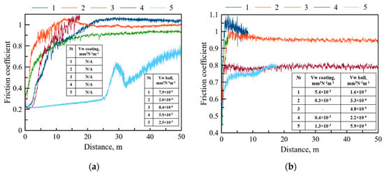
Figure 4.
Friction coefficient vs. distance dependence during testing of coatings against 100Cr6 (a) and Al2O3 (b) counterparts. Inserts show the values of wear rate for coatings and counter-bodies.
When the 100Cr6 ball was used as a counterpart, the behavior of coatings 1–3 was similar. The friction coefficient increased from the initial values of 0.2–0.3 to 0.9–1.1 at a distance of 10–20 m and then stabilized at 1.04 (coating 1), 0.98 (coating 2), and 0.92 (coating 3) and remained relatively constant until the end of the measurements at a distance of 50 m. The behavior of coating 4 obtained at 5 sccm C2H4 at the initial moment of the test was similar to that of coatings 1–3. However, when reaching a distance of 17.5 m, the friction machine automatically stopped the measurement as a result of exceeding the permissible friction coefficient (>1.1). Coating 5 with the highest carbon content showed the lowest and the most stable f ~0.3 at a distance up to 25.7 m, followed by a jump to 0.65 (25.8–32.4 m), and further monotonous increase from 0.39 up to 0.76 at the distance from 32 to 50 m. This behavior can be explained by the positive role of carbon [45,46], as well as by specific tribochemical reactions [47].
In the tests where Al2O3 ball was used as a counterpart, for coatings 1–3, the friction coefficientf increased sharply to values of 0.95–1.05 at a 0–2 m distance. This resulted in the premature termination of tests for samples 1 and 3 at a distance below 10 m as a result of exceeding the permissible values of f. The friction coefficient of sample 2 obtained at 5 sccm N2 was stable after a short run-in period and remained within a 0.95–1 range until the end of the test at 50 m. Coating 4 deposited in a mixture of Ar and C2H4 showed a rapid rise of the f value to 0.8 and then remained stable until the end of the test. Coating 5 with a high carbon content had similar behavior with slightly lower values at distances up to 20 m.
Figure 5 provides three-dimensional profiles of wear tracks after testing with 100Cr6 and Al2O3 balls for coatings 1, 2, and 4.
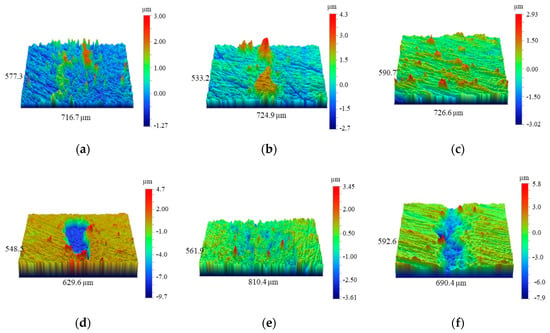
Figure 5.
3D images of wear tracks on the surface of coatings 1(Ar), 2 (5 sccm N2), and 5 (10 sccm C2H4) after testing against 100Cr6 (a–c) and Al2O3 (d–f).
When tested against the steel ball counterpart, none of the coatings 1–5 showed any signs of surface wear; however, noticeable pile-ups of wear debris were present, suggesting that wear of steel ball and adhesion of steel debris to the coatings were the main wear mechanisms. Coatings 1, 2, and 4 had pronounced areas of wear debris accumulation, concentrated in local zones and having a height of 3–5 microns. In the case of coatings 3 and 5 with the maximum nitrogen and carbon concentration, the wear debris was distributed more evenly in the tribocontact zone and had a height of 2–3 microns. The wear rate (Vw) of the steel ball used to test coating 1 was 7.9 × 10⁻⁵ mm3·N−1·m−1 (Figure 4a, insert). The highest (2.0 × 10⁻⁴ mm3·N−1·m−1) and lowest (8.4 × 10⁻⁶ mm3·N−1·m−1) ball wear rates were achieved for nitrogen-rich coatings 2 and 3. The increase of carbon content was associated with the decrease of Vw from 5.9 × 10⁻⁵ (coating 4) to 2.5 × 10⁻⁵ mm3·N−1·m−1 (coating 5).
During the testing with alumina ball counterpart, coating 1 deposited in Ar experienced uneven wear; that is, both segments with no visible wear and areas of complete wear with a depth of ~8 microns were present (Figure 5d). The low wear resistance of coating 1 can be associated with its pronounced columnar structure, characterized by low fracture toughness [35]. The wear rate of the coating was 5.4 × 10⁻³ mm3·N−1·m−1 (Figure 4b, insert). In coatings 2–5, deposited by reactive sputtering, the wear depth did not exceed the coating thickness. In the case of nitrogen-containing coating 2, wear track with a width of 450 microns and depth below 2 microns was observed. The wear rate of the coating was 0.3 × 10⁻³ mm3·N−1·m−1, which is ~20 times lower than the values obtained for the coating 1 deposited in Ar. Coating 3 with the maximum nitrogen content showed no signs of wear (test run ~2 m). Sample 4 obtained at 5 sccm C2H4 demonstrated a wear rate of 0.4 × 10⁻³ mm3 N−1 m−1, which is equivalent to the value for a coating deposited in nitrogen at the same gas flow rate. When the C2H4 flow rate increased to 10 sccm, an increase in the wear rate was observed (1.3 × 10⁻³ mm3·N−1·m−1). Our previous work [23] addressed the case of Ta-Si-C and Ta-Si-C-N coatings produced by sputtering of composite SHS-cathodes TaSiC. The nitrogen-rich coatings (Ta-Si-C-N) showed a low wear rate against Al2O3 ball (1.7–2.8 × 10⁻⁵ mm3·N−1·m−1, whereas their nitrogen-free counterparts suffered complete wear.
The wear areas on alumina balls show that the lowest achieved wear rate was 1.6 × 10⁻⁵ mm3·N−1·m−1 and was achieved for coating 1 (Figure 4b, insert). Nitrogen-rich coatings 2 and 3 were worn at rates 3.3 × 10⁻⁴ and 4.8 × 10⁻⁵ mm3·N−1·m−1, respectively. The wear of counter-bodies for coatings 4 and 5 was 2.2 × 10⁻⁴ and 5.9 × 10⁻⁵ mm3·N−1·m−1, respectively. Therefore, the increase in both carbon and nitrogen content in reactively-deposited coatings is beneficial for the decreased wear of alumina counter-bodies.
The SEM images of the surface of coatings 1–5 annealed at the maximal temperature of 1000 °C are shown in Figure 6.
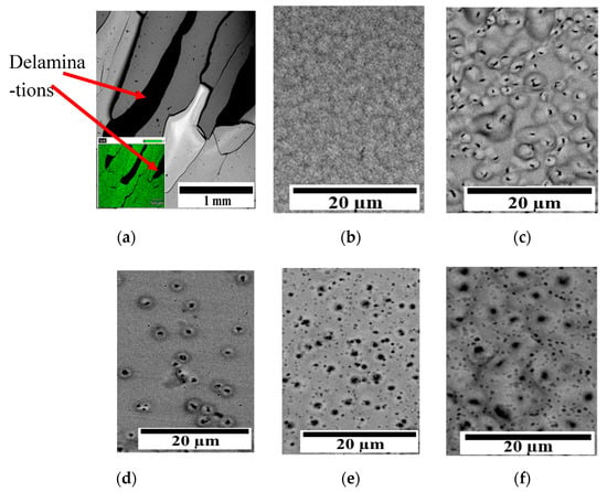
Figure 6.
Top-view SEM images of coatings 1(Ar) (a,b), 2 (5 sccm N2) (c), 3 (10 sccm N2) (d), 4 (5 sccm C2H4) (e), and 5 (10 sccm C2H4) (f) after air annealing with maximal temperature of 1000 °C. Insert on 1a shows the energy dispersive spectroscopy (EDS) map for Ta signal.
The surface of coating 1 deposited in Ar contained visible cracks and delaminations. However, a local uniform microstructure with no visible defects can be seen at ×2000 magnification. The cracks formation likely resulted from the difference in thermal expansion coefficients between the coating and the substrate. As a result, tensile stresses develop along the perimeter of the defect, which leads to the coating’s destruction [48]. For coating 2 obtained at 5 sccm N2, a specific structure (Figure 6b), resembling blisters or bubbles was observed after the annealing. The formation of cavities or pores can be associated with the oxidation of nitrogen-containing phases in the coating and subsequent release of gaseous nitrogen oxides through the oxide film at high temperatures [37]. The bubbles occupied about 85% of the surface area of coating 2. When the N2 flow rate increased to 10 sccm (coating 3), a reduction in the number of bubbles was observed and the total area of defects was ~10% of the surface area. Samples 4 and 5 showed the same defective structure, with open pores (~0.1–2 microns) occupying up to ~75% of the surface. The formation of pores is caused by the accumulation of COx in the upper layer of the coating and the formation of blisters, which, under a certain gas pressure, burst and form pores on the surface [49].
SEM cross-section images of annealed coatings 1–5 are shown in Figure 7.
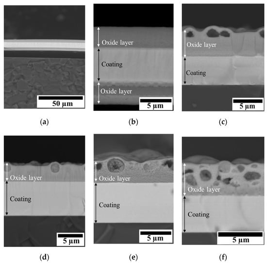
Figure 7.
Cross-section SEM images of coatings 1 (Ar) (a,b), 2 (5 sccm N2) (c), 3 (10 sccm N2) (d), 4 (5 sccm C2H4) (e), and 5 (10 sccm C2H4) (f) after air annealing with maximal temperature of 1000 °C.
Coating 1 has experienced delamination from the substrate during the annealing (Figure 7a) and the formation of oxide layers on both sides of the coating. The oxide layer was pore-free, with a maximum thickness of 3.5 microns, and was comprised mainly of SiOx and TaOx. Cross-section SEM images of sample 2 show a porous oxide layer with a thickness of 4.4 microns. Pores (d = 0.2–2.0 microns) were concentrated in the upper part of the oxide layer. With an increase in the nitrogen content, the thickness of the oxide layer decreased by 23% and amounted to 3.4 microns. Coating 4 obtained at 5 sccm C2H4 showed an oxide layer thickness of 3.6 microns. The formed SiOx-TaOx oxide film had a loose structure with a pore size up to ~2.6 microns. The oxide layer of sample 5 with a thickness of 3.8 microns also had a porous structure. Pores with 0.2–1.5 microns diameter were randomly distributed over the thickness of the oxide layer. Coating 2 obtained at 5 sccm N2 had the maximum thickness of the oxide layer (Table 2), and the minimum thickness of the oxide layer was characteristic of sample 3, deposited at a flow rate of N2 10 sccm.
4. Discussion
4.1. Dependence of Growth Kinetics and Microstructure on the Gas Environment
The coating deposition kinetics was dependent on the composition of the sputtering atmosphere. The introduction of N2 (10 sccm) into Ar flow resulted in an 11% increase in growth rate (coating 3, Table 2), whereas the introduction of a similar amount of C2H4 slightly decreased the growth rate. Both nitrogen and carbon formed related phases in the coatings, suggesting that the difference in growth rates arises from different ionization behavior of N2 and C2H4 and higher scattering of atoms of sputtered material by C2H4 molecules (Table 1). The decrease in the size of h-TaSi2 crystallites and the amorphization of coatings deposited in a reactive atmosphere is associated with the formation of new TaN and TaC phases, which apparently interrupt the growth of h-TaSi2 crystallites. Reactive sputtering was instrumental in eliminating the unwanted columnar structures in the coatings (Figure 2). Columnar structures are known to adversely affect the mechanical and tribological properties of coatings, as well as their oxidation resistance [34,35].
4.2. Mechanical and Tribological Properties
Reactive deposition in both Ar-N2 and Ar-C2H4 resulted in the enhancement of mechanical properties and tribological performance of the coatings. The increase of mechanical properties can be partially attributed to the growth of internal stresses (Table 2). In the case of N-containing coatings, this effect might be associated with the formation of a crystalline/amorphous phase based on TaN [38,39], as well as a decrease in the size of crystallites [40]. In C-doped coatings, the rise in hardness is due to the formation of a hard DLC-phase, as well as the positive effect of microstructural modification via the introduction of carbon into the composition of the coating. The complete understanding of structural features and phase composition of reactive coatings requires additional studies, which we plan to do next.
All the coatings investigated in this work were characterized by a high friction coefficient when relatively soft material (steel 100Cr6, H = 8 GPa) was used as a counterpart. The surface of the coating is much harder (H = 12–30 GPa), and has high adhesion to steel, similar to [5]. The distinct behavior of coating 5 at the initial part of testing distance can be associated with the positive role of free carbon, which could be released owing to the oversaturation of the crystalline carbide phase and plays the role of a solid lubricant during friction [45,46]. Thus, coating 5 obtained at a flow rate of 10 sccm C2H4 had the lowest friction coefficient f in contact with the 100Cr6 steel ball. Under more stringent conditions (Al2O3 counterpart), the lowest f was demonstrated by sample 4 deposited at 5 sccm C2H4. The coating obtained at 5 sccm N2 had a stable friction coefficient against both counterparts (100Cr6 steel and Al2O3). The transition to reactive sputtering leads to a decrease in the coatings’ wear rate, which coincides with the results of other works [41,47]. The best wear resistance was recorded for coatings 2 and 4, obtained at 5 sccm in N2 and C2H4. This effect can be attributed to the presence of amorphous solid lubricant phases.
4.3. Oxidation Resistance
The oxidation testing confirmed that the non-reactive coating was characterized by the lowest adhesion to the substrates, as this was the only coating that experienced complete delamination (Figure 7). However, its oxidation behavior was superior to other coatings, because the as-formed oxide layer was dense and contained neither pores nor blisters. The sublimation of boron oxide is a known problem for refractory borides [50,51,52], so the lack of gas porosity in the Zr-Ta-Si-B coatings is remarkable. Despite increasing the adhesion, preventing the delamination, and enhancing the mechanical and tribological performance, the reactive sputtering clearly resulted in pronounced pore formation in the as-formed oxide layer upon annealing. The pores were formed by the oxidation of nitrogen- and carbon-containing phases to gaseous oxides. The blistering of the oxide layer is to be avoided if one strives to produce coatings with the highest possible oxidation resistance. The best trade-off between tribological performance and oxide layer porosity was achieved for coating 4. This coating was characterized by the lowest wear rate and propinquity to pore-formation upon oxidation among the investigated reactively deposited coatings. A further improvement might be achieved by the deposition of functionally graded coatings with the lower layer produced by reactive sputtering and upper layer deposited in Ar.
In addition, short-term annealing in air at 1200 °C for 10 min was also performed to assess the maximum operating temperature. It was found that the non-reactive coating completely oxidizes under these conditions. The thickness of the oxide layer for nitrogen-containing coatings 2 and 3 was about 8 microns (Table 2). Coating 5 with the maximum carbon content formed a 6.9 micron thick oxide layer. The lowest oxide thickness of 3.6 microns and the highest non-oxidized layer thickness of 6.2 microns were observed for coating 4 (Figure 8), in line with the results at 1000 °C.
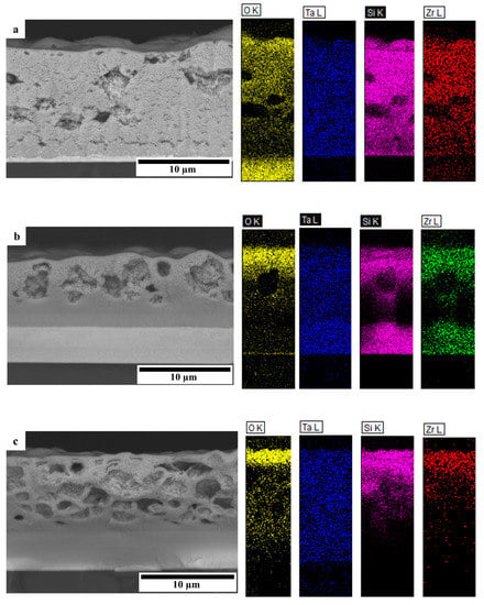
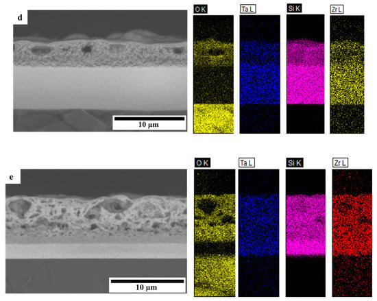
Figure 8.
Cross-section SEM images and EDS maps of coatings 1 (Ar) (a), 2 (5 sccm N2) (b), 3 (10 sccm N2) (c), 4 (5 sccm C2H4) (d), and 5 (10 sccm C2H4) (e) annealed at 1200 °C for 10 min.
From the SEM-EDS data, it can be seen that a top-layer is formed on the surface of the coating, consisting mainly of silicon and tantalum oxides. Under the oxide film is an oxygen-free layer containing all the main elements of the coating, which has not undergone noticeable recrystallization.
Further analysis of oxidation mechanisms was based on XRD screening of coatings 2–5 annealed at 1200 °C for 10 min (Figure 9).
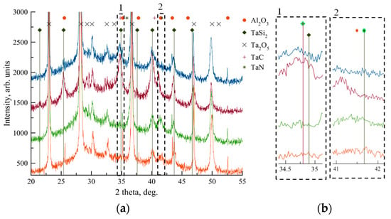
Figure 9.
XRD patterns of coatings 2 (5 sccm N2), 3 (10 sccm N2), 4 (5 sccm C2H4), and 5 (10 sccm C2H4) after annealing at 1200 °C for 10 min: overview diffractograms (a) and enlarged areas (b).
A signal from alumina substrate can be recognized in all tested specimens after exposure to 1200 °C. A set of peaks that correlate well with (100), (101), (102), (110), (111), (200), (201), and (103) planes of the hexagonal h-TaSi2. The highest characteristic peaks h-TaSi2 (111) and (200) are located at 2Ө = 40.1° and 43.7°, respectively. Intense peaks at 2Ө = 23.0, 28.3, 36.7, and 47.0 are related to oxidation product Ta2O5. In the case of nitrogen-rich coatings 2 and 3, the peaks for cubic TaN were found, with the highest peak at 2Ө = 41.7° (Figure 9b). The coatings deposited in C2H4 show the presence of (111) and (200) planes of FCC-TaC, with a corresponding highest peak at 2Ө = 34.8° (Figure 9b). The crystallite structure of h-TaSi2 calculated based on the broadening of (111) peak was 6–10 nm for all coatings. XRD patters corroborate that the reactive-sputtered coatings 2–5 are relatively stable and resistant to corrosion at temperatures up to 1200 °C.
5. Conclusions
Coatings with a thickness of 6–8 microns were obtained by magnetron sputtering of the TaSi2-Ta3B4-(Ta,Zr)B2 target in the Ar environment and gas mixtures Ar-N2 and Ar-C2H4. The coating deposited in argon had a pronounced columnar structure, while the transition to reactive sputtering suppressed the column growth. The main constituent of Ar-sputtered coatings was the h-TaSi2 phase with a crystallite size of ~10 nm. During the deposition in Ar-N2 and Ar-C2H4, a decrease in grain size, partial amorphization, and the formation of new phases based on TaN and TaC were observed. The coatings obtained at the maximum flow rate of N2 and C2H4 had high hardness at the level of 28–29 GPa and elastic recovery of 76%–78%. The transition to reactive deposition reduced the friction coefficient and the coatings’ wear rate. All studied coatings resisted oxidation in the air up to 1000 °C owing to the formation of protective Ta-Si-O oxide films. Sputtering at optimal nitrogen and carbon concentrations modified the structure and increased the heat resistance and thermal cycling resistance of the coatings. The reactively-deposited coatings can briefly resist oxidation at 1200 °C.
The combination of high mechanical and tribological characteristics with high oxidation resistance makes the coatings in the Ta-Zr-Si-B-C-N system promising as protective coatings for various high-temperature applications, including high-performance dry machining tools and parts of heavily loaded friction units operating in aggressive environments, among others.
Author Contributions
Supervision, Deposition, Annealing, Investigation, Conceptualization, Writing & Editing: P.V.K.-K.; Tribo-Investigation, Profilometry, Analysis, Calculations, Writing: A.D.S.; Translation and Editing: S.A.V.; Investigation: V.V.K.; Formal Analysis: V.Y.L.; Project Administration, Resources: E.A.L. All authors have read and agreed to the published version of the manuscript.
Funding
The research was funded by the Ministry of Science and Higher Education of the Russian Federation (Project No. 0718-2020-0034 of State assignment).
Acknowledgments
The authors are grateful to M.I. Petrzhik for the nanoindentation tests, N.V. Shvyndina for the SEM-EDS study, and P.A. Loginov for the XRD and HR TEM studies.
Conflicts of Interest
The authors declare no conflict of interest.
References
- He, Q.; Paiva, J.M.; Kohlscheen, J.; Beake, B.D.; Veldhuis, S.C. An integrative approach to coating/carbide substrate design of CVD and PVD coated cutting tools during the machining of austenitic stainless steel. Ceram. Int. 2020, 46, 5149–5158. [Google Scholar] [CrossRef]
- Vereschaka, A.; Tabakov, V.; Grigoriev, S.; Sitnikov, N.; Oganyan, G.; Andreev, N.; Milovich, F. Investigation of wear dynamics for cutting tools with multilayer composite nanostructured coatings in turning constructional steel. Wear 2019, 420–421, 17–37. [Google Scholar] [CrossRef]
- Kiryukhantsev-Korneev, F.V.; Sheveiko, A.N.; Komarov, V.A.; Blanter, M.S.; Skryleva, E.A.; Shirmanov, N.A.; Levashov, E.A.; Shtansky, D.V. Nanostructured Ti-Cr-B-N and Ti-Cr-Si-C-N coatings for hard-alloy cutting tools. Russ. J. Non-Ferrous Met. 2011, 52, 311–318. [Google Scholar] [CrossRef]
- Vereschaka, A.; Tabakov, V.; Grigoriev, S.; Sitnikov, N.; Milovich, F.; Andreev, N.; Bublikov, J. Investigation of wear mechanisms for the rake face of a cutting tool with a multilayer composite nanostructured Cr–CrN-(Ti,Cr,Al,Si)N coating in high-speed steel turning. Wear 2019, 438–439, 203069. [Google Scholar] [CrossRef]
- Kiryukhantsev-Korneev, P.V.; Pierson, J.F.; Bychkova, M.Y.; Manakova, O.S.; Levashov, E.A.; Shtansky, D.V. Comparative Study of Sliding, Scratching, and Impact-Loading Behavior of Hard CrB2 and Cr–B–N Films. Tribol. Lett. 2016, 63, 44–55. [Google Scholar] [CrossRef]
- Shon, I.-J.; Ko, I.-Y.; Chae, S.-M.; Nа, K. Rapid consolidation of nanostructured TaSi2 from mechanochemically synthesized powder by high frequency induction heated sintering. Ceram. Int. 2011, 37, 679–682. [Google Scholar] [CrossRef]
- Samsonov, G.V.; Vinitsky, I.V. Refractory Compounds: Handbook; Metallurgy: Moscow, Russia, 1976; p. 558. [Google Scholar]
- Buecher, W.; Schliebs, R.; Winter, G.; Buechel, K.H. Industrielle Angewandte Chemie; Verlag Chemie: Weinheim, Germany, 1984. [Google Scholar]
- Zhang, Y.-L.; Ren, J.; Tian, S.; Li, H.; Ren, X.; Hu, Z. HfC nanowire-toughened TaSi2–TaC–SiC–Si multiphase coating for C/C composites against oxidation. Corro. Sci. 2015, 90, 554–561. [Google Scholar] [CrossRef]
- Shi, X.H.; Zeng, X.R.; Li, H.J.; Fu, Q.G.; Zou, J.Z. TaSi 2 Oxidation Protective Coating for SiC Coated Carbon/Carbon Composites. Rare Met. Mater. Eng. 2011, 40, 403–406. [Google Scholar] [CrossRef]
- Liu, F.; Li, H.; Gu, S.; Yao, X.; Fu, Q. Ablation behavior and thermal protection performance of TaSi2 coating for SiC coated carbon/carbon composites. Ceram. Int. 2019, 45, 3256–3262. [Google Scholar] [CrossRef]
- Du, B.; Zhou, S.; Zhang, X.; Hong, C.; Qu, Q. Preparation of a high spectral emissivity TaSi2-based hybrid coating on SiOC-modified carbon-bonded carbon fiber composite by a flash sintering method. Surf. Coat. Technol. 2018, 350, 146–153. [Google Scholar] [CrossRef]
- Tao, X.; Li, X.; Guo, L.; Xu, X.; Guo, A.; Hou, F.; Liu, J. Effect of TaSi2 content on the structure and properties of TaSi2-MoSi2-borosilicate glass coating on fibrous insulations for enhanced surficial thermal radiation. Surf. Coat. Technol. 2017, 316, 122–130. [Google Scholar] [CrossRef]
- Mansour, A.N. Effect of temperature on microstructure and electrical properties of TaSi2 thin films grown on Si substrates. Vacuum 2011, 85, 667–671. [Google Scholar] [CrossRef]
- Ringeisen, F.; Alaoui, M.; Bolmont, D.; Koulmann, J.J. Oxidation of TaSi2 thin films on polycrystalline tantalum. Appl. Surf. Sci. 1992, 62, 167–173. [Google Scholar] [CrossRef]
- Schultes, G.; Schmitt, M.; Goettel, D.; Freitag-Weber, O. Strain sensitivity of TiB2, TiSi2, TaSi2 and WSi2 thin films as possible candidates for high temperature strain gauges. Sens. Actuators A Phys. 2006, 126, 287–291. [Google Scholar] [CrossRef]
- Sidorenko, S.I. Formation of Nanocrystalline Structure of TaSi2 Films on Silicon. Powder Metall. Met. Ceram. 2003, 42, 14–18. [Google Scholar] [CrossRef]
- Inui, H.; Fujii, A.; Hashimoto, T.; Tanaka, K.; Yamaguchi, M.; Ishizuk, K. Defect structures in TaSi2 thin films produced by co-sputtering. Acta Mater. 2003, 51, 2285–2296. [Google Scholar] [CrossRef]
- Xu, J.; Xie, Q.; Peng, S.; Li, Z.; Jiang, S. Investigation of slurry erosion-corrosion behavior of Ta(Si1−xAlx)2 nanocrystalline coatings. Mater. Res. Express 2020, 7, 026408. [Google Scholar] [CrossRef]
- Xu, J.; Zhang, S.K.; Lu, X.L.; Jiang, S.; Munro, P.; Xie, Z.-H. Effect of Al alloying on cavitation erosion behavior of TaSi2 nanocrystalline coatings. Ultrason. Sonochem. 2019, 59, 104742. [Google Scholar] [CrossRef]
- Lai, J.J.; Lin, Y.S.; Chang, C.H.; Wei, T.Y.; Huang, J.C.; Liao, Z.X.; Lin, C.H.; Chen, C.H. Promising Ta-Ti-Zr-Si metallic glass coating without cytotoxic elements for bio-implant applications. Appl. Surf. Sci. 2018, 427, 485–495. [Google Scholar] [CrossRef]
- Oleksak, R.P.; Devaraj, A.; Herman, G.S. Atomic-scale structural evolution of Ta–Ni–Si amorphous metal thin films. Mater. Lett. 2016, 164, 9–14. [Google Scholar] [CrossRef]
- Bondarev, A.V.; Vorotilo, S.; Shchetinin, I.V.; Levashov, E.A.; Shtansky, D.V. Fabrication of Ta-Si-C targets and their utilization for deposition of low friction wear resistant nanocomposite Si-Ta-C-(N) coatings intended for wide temperature range tribological applications. Surf. Coat. Technol. 2019, 359, 342–353. [Google Scholar] [CrossRef]
- Yoon, J.-K.; Kim, G.-H.; Kim, H.-S.; Shon, I.-J.; Kim, J.-S.; Doh, J.-M. Microstructure and oxidation behavior of in situ formed TaSi2–Si3N4 nanocomposite coating grown on Ta substrate. Intermetallics 2008, 16, 1263–1272. [Google Scholar] [CrossRef]
- Chung, C.K.; Chen, T.S. Effect of Si/Ta and nitrogen ratios on the thermal stability of Ta–Si–N thin films. Microelectron. Eng. 2020, 87, 129–134. [Google Scholar] [CrossRef]
- Olowolafe, J.O.; Rau, I.; Unruh, K.M.; Swann, C.P.; Jawad, Z.S.; Alford, T. Effect of composition on thermal stability and electrical resistivity of Ta–Si–N films. Thin Solid Films 2000, 365, 19–21. [Google Scholar] [CrossRef]
- Nah, J.W.; Choi, W.S.; Hwang, S.K.; Lee, C.M. Chemical state of (Ta, Si)N reactively sputtered coating on a high-speed steel substrate. Surf. Coat. Technol. 2000, 123, 1–7. [Google Scholar] [CrossRef]
- Chen, Y.-I.; Cheng, Y.-R.; Chang, L.-C.; Lu, T.-S. Chemical inertness of Ta–Si–N coatings in glass molding. Thin Solid Films. 2015, 584, 66–71. [Google Scholar] [CrossRef]
- Zeman, P.; Musil, J.; Daniel, R. High-temperature oxidation resistance of Ta–Si–N films with a high Si content. Surf. Coat. Technol. 2006, 200, 4091–4096. [Google Scholar] [CrossRef]
- Kiryukhantsev-Korneev, P.V.; Iatsyuk, I.V.; Shvindina, N.V.; Levashov, E.A.; Shtansky, D.V. Comparative investigation of structure, mechanical properties, and oxidation resistance of Mo-Si-B and Mo-Al-Si-B coatings. Corr. Sci. 2017, 123, 319–327. [Google Scholar] [CrossRef]
- Levashov, E.A.; Mukasyan, A.S.; Rogachev, A.S.; Shtansky, D.V. Self-propagating high-temperature synthesis of advanced materials and coatings. Int. Mater. Rev. 2017, 62, 203–239. [Google Scholar] [CrossRef]
- Shtansky, D.V.; Sheveyko, A.N.; Sorokin, D.I.; Lev, L.C.; Mavrin, B.N.; Kiryukhantsev-Korneev, P.V. Structure and properties of multi-component and multilayer TiCrBN/WSex coatings deposited by sputtering of TiCrB and WSe2 targets. Surf. Coat. Technol. 2008, 202, 5953–5961. [Google Scholar] [CrossRef]
- Levashov, E.A.; Shtansky, D.V.; KiryukhantsevKorneev, P.V.; Petrzhik, M.I.; Tyurina, M.Y.; Sheveiko, A.N. Multifunctional nanostructured coatings: Formation, structure, and the uniformity of measuring their mechanical and tribological properties. Russ. Metall. 2010, 10, 917–935. [Google Scholar] [CrossRef]
- Avila, P.R.T.; da Silva, E.P.; Rodrigues, A.M.; Aristizabal, K.; Pineda, F.; Coelho, R.S.; Garcia, G.L.; Soldera, F.; Walczak, M.; Pinto, H.C. On manufacturing multilayer-like nanostructures using misorientation gradients in PVD films. Sci. Rep. 2019, 9, 15898. [Google Scholar] [CrossRef] [PubMed]
- Szala, M.; Walczak, M.; Pasierbiewicz, K.; Kamiński, M. Cavitation Erosion and Sliding Wear Mechanisms of AlTiN and TiAlN Films Deposited on Stainless Steel Substrate. Coatings 2019, 9, 340. [Google Scholar] [CrossRef]
- Niu, Y.; Huang, L.; Zhai, C.; Zeng, Y.; Zheng, X.; Ding, C. Microstructure and thermal stability of TaSi2 coating fabricated by vacuum plasma spray. Surf. Coat. Technol. 2015, 279, 1–8. [Google Scholar] [CrossRef]
- Chen, Y.-I.; Lin, K.-Y.; Wang, H.-H.; Cheng, Y.-R. Characterization of Ta–Si–N coatings prepared using direct current magnetron co-sputtering. Appl. Surf. Sci. 2014, 305, 805–816. [Google Scholar] [CrossRef]
- Nah, J.W.; Hwang, S.K.; Lee, C.M. Development of a complex heat resistant hard coating based on (Ta, Si)N by reactive sputtering. Mater. Chem. Phys. 2000, 62, 115–121. [Google Scholar] [CrossRef]
- Koller, C.M.; Marihart, H.; Bolvardi, H.; Kolozsvari, S.; Mayrhofer, P.H. Structure, phase evolution, and mechanical properties of DC, pulsed DC, and high power impulse magnetron sputtered Ta–N films. Surf. Coat. Technol. 2018, 347, 304–312. [Google Scholar] [CrossRef]
- Liu, X.; Yuan, F.; Wei, Y. Grain size effect on the hardness of nanocrystal measured by the nanosize indenter. Appl. Surf. Sci. 2013, 279, 159–166. [Google Scholar] [CrossRef]
- Poladi, A.; Mohammadian Semnani, H.R.; Emadoddin, E.; Mahboubi, F.; Ghomi, H.R. Nanostructured TaC film deposited by reactive magnetron sputtering: Influence of gas concentration on structural, mechanical, wear and corrosion properties. Ceram. Int. 2019, 45, 8095–8107. [Google Scholar] [CrossRef]
- Hu, J.; Li, H.; Li, J.; Huang, J.; Kong, J.; Zhu, H.; Xiong, D. Structure, mechanical and tribological properties of TaCx composite films with different graphite powers. J. Alloys Compd. 2020, 832, 153769. [Google Scholar] [CrossRef]
- Leyland, A.; Matthews, A. On the significance of the H/E ratio in wear control: A nanocomposite coating approach to optimised tribological behavior. Wear 2000, 246, 1–11. [Google Scholar] [CrossRef]
- Levashov, E.A.; Petrzhik, M.I.; Shtansky, D.V.; Kiryukhantsev-Korneev, P.V.; Sheveyko, A.N.; Valiev, R.Z.; Gunderov, D.V.; Prokoshkin, S.D.; Korotitskiy, A.V.; Smolin, A.Y. Nanostructured titanium alloys and multicomponent bioactive films: Mechanical behavior at indentation. Mater. Sci. Eng. A 2013, 570, 51–62. [Google Scholar] [CrossRef]
- Shtansky, D.V.; Bondarev, A.V.; Kiryukhantsev-Korneev, P.V.; Sheveyko, A.N.; Pogozhev, Y.S. Influence of Zr and O on the structure and properties of TiC(N) coatings deposited by magnetron sputtering of composite TiC0.5+ZrO2 and (Ti, Zr)C0.5+ZrO2 targets. Surf. Coat. Technol. 2012, 206, 2506–2514. [Google Scholar] [CrossRef]
- Martinez-Martinez, D.; Lopez-Cartes, C.; Justo, A.; Fernandez, A.; Sanchez-Lopez, J.C. Self-lubricating Ti–C–N nanocomposite coatings prepared by double magnetron sputtering. Solid State Sci. 2009, 11, 660–670. [Google Scholar] [CrossRef]
- Du, S.; Zhang, K.; Meng, Q.; Ren, P.; Hu, C.; Wen, M.; Zheng, W. N dependent tribochemistry: Achieving superhard wear-resistant low-friction TaCxNy films. Surf. Coat. Technol. 2017, 328, 378–389. [Google Scholar] [CrossRef]
- Khanna, A.S. Introduction to High Temperature Oxidation and Corrosion; ASM International: Materials Park, OH, USA, 2002; p. 101. [Google Scholar]
- Evans, H.E. Cracking and spalling of protective oxide layers. Mater. Sci. Eng. A 1989, 120–121, 139–146. [Google Scholar] [CrossRef]
- Pan, X.; Li, C.; Niu, Y.; Zhong, X.; Huang, L.; Zeng, Y.; Zheng, X. Effect of Yb2O3 addition on oxidation/ablation behaviors of ZrB2-MoSi2 composite coating under different environment. Corr. Sci. 2020, 175, 108882. [Google Scholar] [CrossRef]
- Wang, J.; Li, B.; Li, R.; Chen, X.; Wang, T.; Zhang, G. Unprecedented oxidation resistance at 900 °C of Mo–Si–B composite with addition of ZrB2. Ceram. Int. 2020, 46, 14632–14639. [Google Scholar] [CrossRef]
- Hassan, R.; Kundu, R.; Balani, K. Oxidation behavior of coarse and fine SiC reinforced ZrB2 at re-entry and atmospheric oxygen pressures. Ceram. Int. 2020, 46, 11056–11065. [Google Scholar] [CrossRef]
© 2020 by the authors. Licensee MDPI, Basel, Switzerland. This article is an open access article distributed under the terms and conditions of the Creative Commons Attribution (CC BY) license (http://creativecommons.org/licenses/by/4.0/).