3.1. Surface Morphology of the Layers
Nitrided layer tracks, fabricated in pure and different mixed gas atmospheres of nitrogen and argon, were studied.
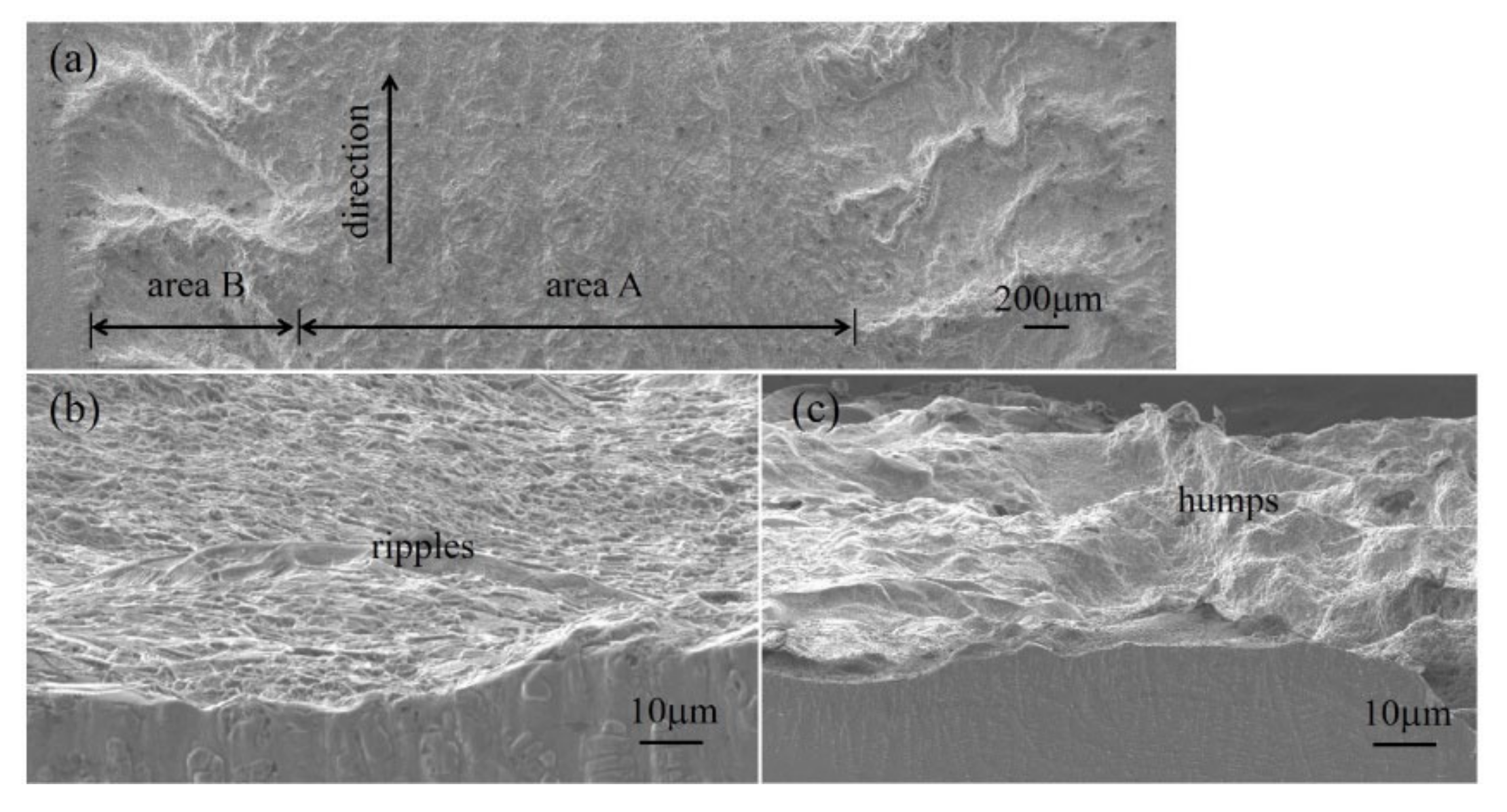
Figure 2 shows the surface morphology of one track nitrided in a gas atmosphere of 80% nitrogen and 20% argon. The direction of laser motion is indicated by the black arrow (
Figure 2a). To highlight the surface characteristics of the nitrided layer, the surface image was labeled with Area A and Area B, which are shown in more detail in
Figure 2b,c respectively.
Area A shows smoother surface characteristics, in comparison to Area B, and appeared more golden in color. The intensity of surface color is known to be positively correlated with higher nitrogen content of the layer, as previously observed by others. The convection strength reduces when the nitrogen concentration of the nitrogen–argon gas atmosphere varied from 91% to 10%. This is due to a reduction in nitrogen gas involved in the reaction, which reduces the temperature of the pool. Here, the amount of titanium nitride (which has a high melting point) decreases, consequently resulting in a molten pool of lower viscosity. The gas flow from the annular nozzle then causes turbulence in the molten pool surface, and a ripple structure is formed (
Figure 2b). These convection-based ripple effects do not occur in pure 100% nitrogen atmospheres or in atmospheres with less than 5% nitrogen, indicating that the structure can be drastically affected.
Area B is the transition region near the fusion line between the substrate and the nitrided tracks. It shows the concentrated regions of craters and humps (
Figure 2a,c). The humps are thought to correspond to nitrogen-rich cells, and the craters to the titanium-rich cellular region, as previously observed [
12].
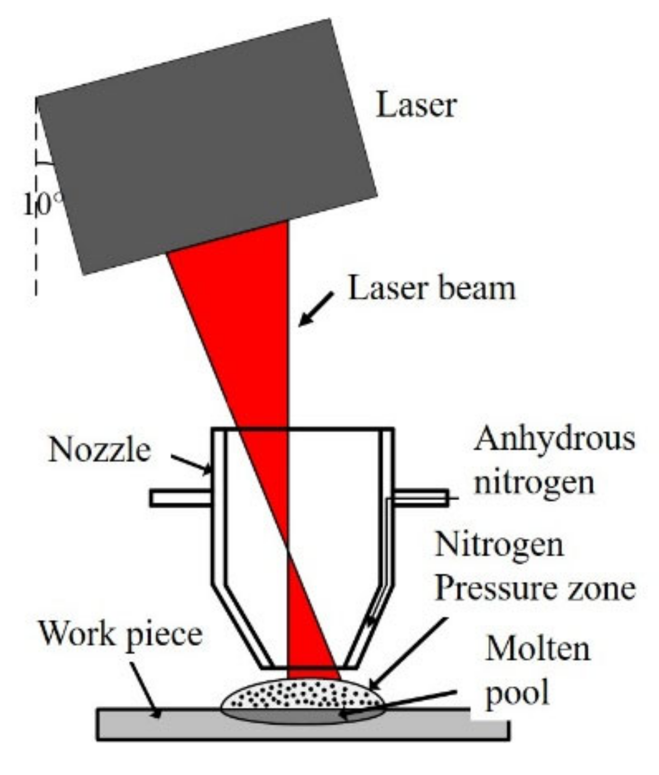
The volume of the molten pool increases as the laser beam irradiates the substrate, which then also influences the surface tension of the pool. These effects control the flow of the metal fluid in the molten pool by Marangoni convection. Based on the phase diagrams of Ti–Al, Ti–V, Ti–Fe, and Ti-N, the dissolution of elements Al, V, and Fe causes decreases in the melting point of the titanium solutions. However, nitrogen (N) causes the melting point of titanium solution to rise. In the process of laser gas nitriding, a titanium solution absorbs a large amount of nitrogen, and the melting point rises more than 1668 °C. Here, strong convection leads to a nitrogen-containing melt overflow from the edge of the molten pool. It nucleates and solidifies immediately upon contact with the low-temperature un-melted substrate, and the solidification front has a cellular structure (
Figure 2c). The cellular structure of the humped region, which represents the trailing edge of the molten pool, has been observed previously and can be explained by the Cline and Anthony model [
13].
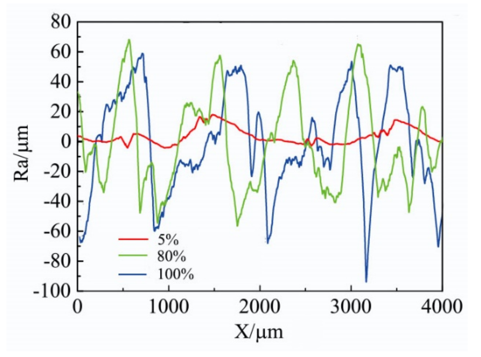
The surface roughness of the nitrided layer improved dramatically (becoming smoother) with a gas atmosphere of 5% nitrogen and 95% argon.
Figure 3 shows the surface roughness (
Ra) of the nitrided layers obtained for gas atmospheres of 100%, 80%, and 5% nitrogen (in argon) at positions along the surface of the layer. Compared with a maximum roughness depth (
Rmax) of 95 μm in the pure 100% nitrogen atmosphere (blue line), the maximum obtained in the 5% nitrogen and 95% argon atmosphere (red line) was reduced by at least four times to 23 μm (
Figure 3). This depth meets the demands of several engineering applications. Thus, the surface roughness of the layer can be improved significantly by diluting the nitrogen atmosphere with argon.
3.2. Hardness of the Layers
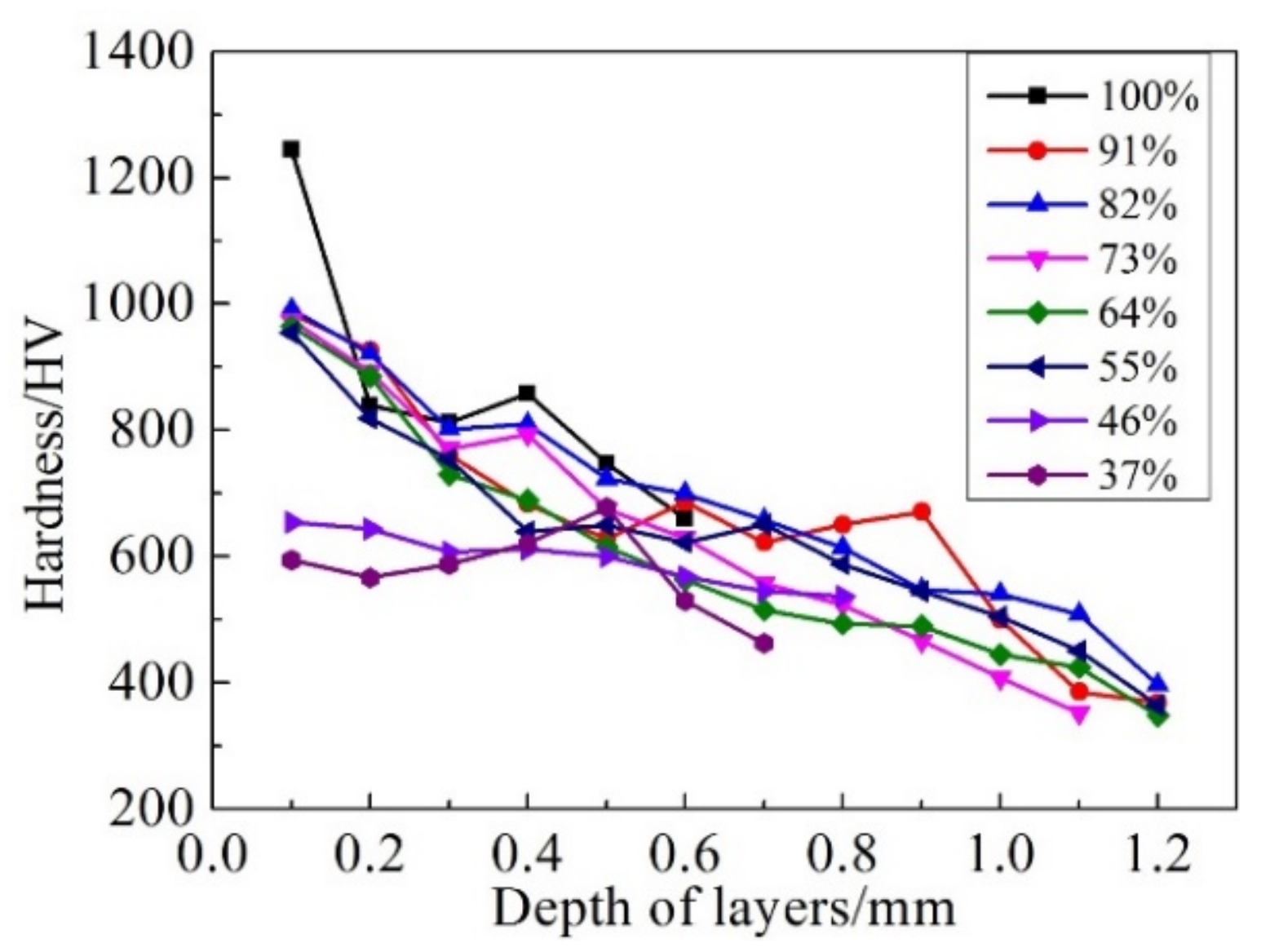
The hardness profiles, along the cross section of the nitrided layers, showed that the surface hardness reached a maximum value in the pure (100%) nitrogen atmosphere (
Figure 4). This is because, compared with the mixed nitrogen and argon atmospheres, the amount of titanium nitride in the nitrided layer increased. However, the hardness gradient of the nitrided layer, from the surface to the substrate, in the pure nitrogen atmosphere was steeper than that in the dilute nitrogen–argon atmospheres. The amount of nitrogen in the molten pool determines the pool temperature, which then determines the dissolution and diffusion of nitrogen into the pool, therefore, there is a nitrogen concentration gradient in the depth direction (surface to matrix) of the nitrided layer, as observed previously [
14]. Thus, the hardness values at different positions along the nitrided layer are dependent on the nitrogen gas concentration of the atmosphere.
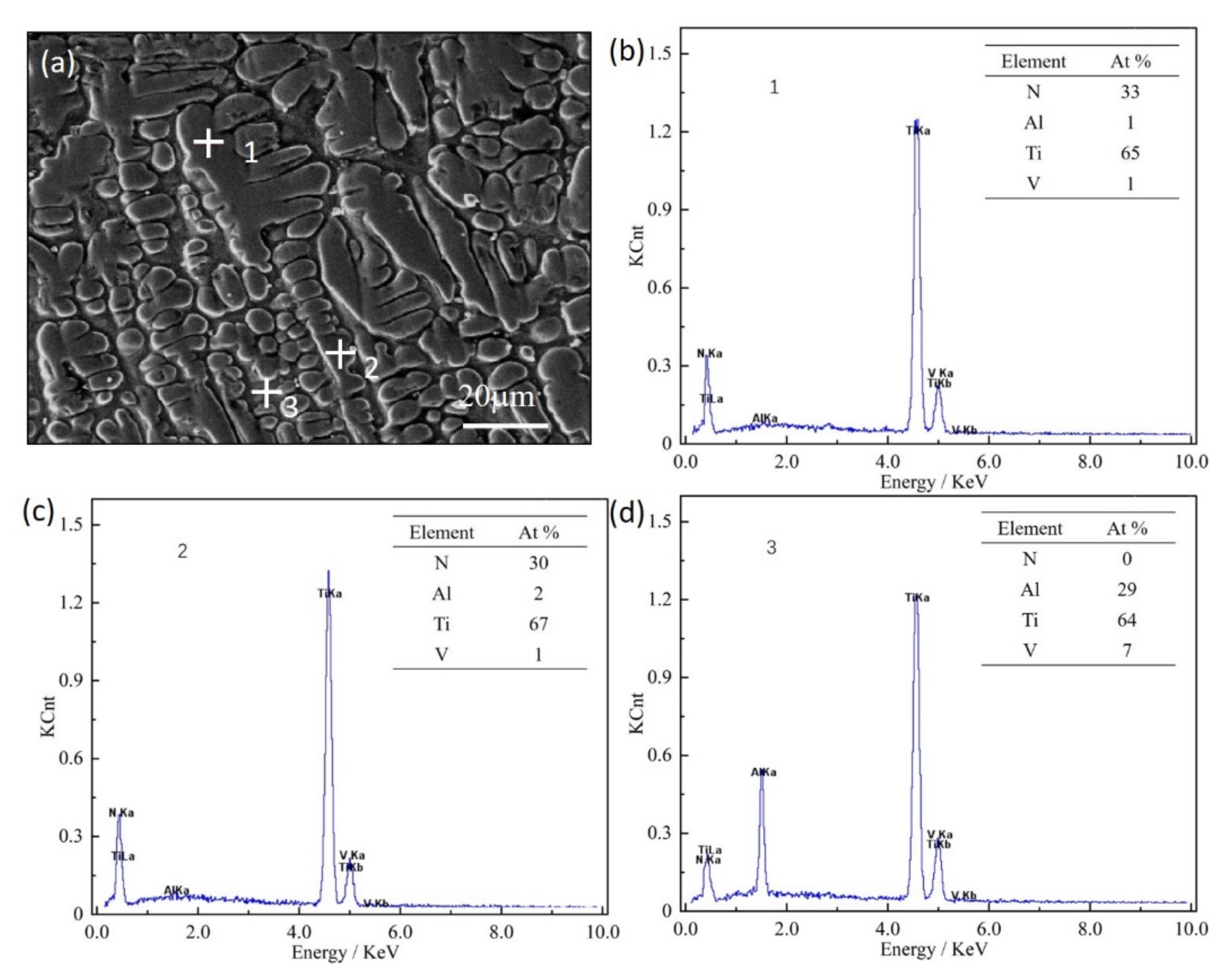
Energy spectrum curves of energy dispersive X-ray spectroscopy (EDX) point scanning on the cross section of the nitrided layer are shown in
Figure 5. Positions 1 and 2 were located on dendrites of different depths (Position 2 was deeper than Position 1), and Position 3 was located on the structure between dendrites. The results showed that the nitrogen content between the dendrites was significantly smaller than that of the dendrites. The nitrogen content of the dendrites also decreased as the depth of the nitrided layer increased (
Figure 5b,c).
Overall, the surface hardness decreased dramatically when the amount of nitrogen in the nitrogen–argon atmosphere was less than 50% (
Figure 4). There are at least three reasons for this: first, nitriding occurs through a process of nitrogen diffusion, hence, nitrogen has a gradient distribution, and the amount of titanium nitride and phase type vary along the depth of the nitrided layer [
15]; second, the thin planar TiN on the layer surface, and the dense titanium nitride underneath it, restricts nitrogen diffusion through the surface and into the bottom of the molten pool, so the nitrogen content in the molten pool decreases; and finally, the nitrogen concentration at the surface of the molten pool is influenced by the concentration of nitrogen present so that the amount of TiN
x in that region is changed [
15]. Thus, it follows that laser gas nitriding in a nitrogen–argon atmosphere (as opposed to purely nitrogen) is at the expense of decreasing the hardness of the layer. For example, the surface microhardness of the nitrided layer is around 600 HV in 5% nitrogen and 95% argon, but 1240 HV in pure (100%) nitrogen.
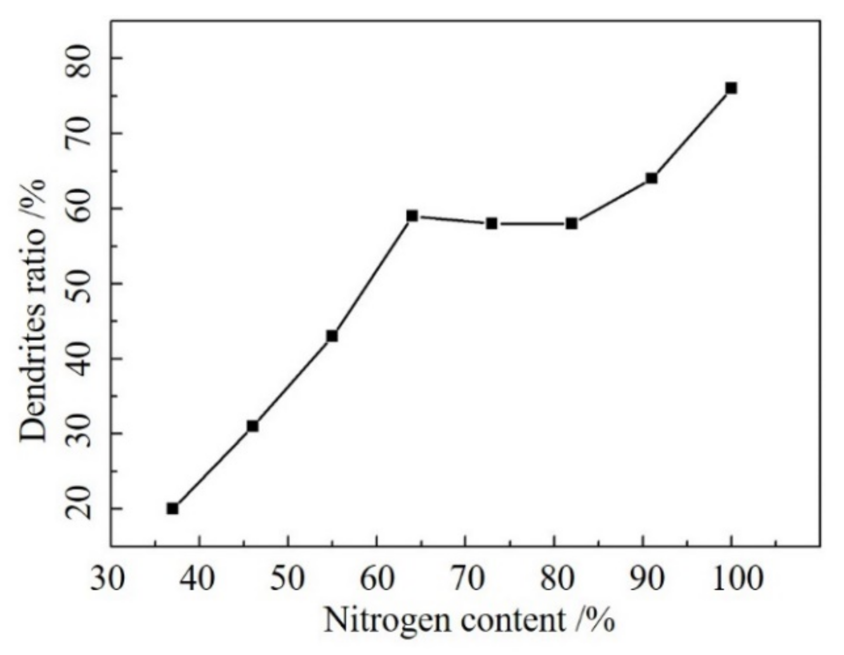
The relationship between nitrogen content and dendrite area fraction in the cross section of the nitrided layer is shown in
Figure 6. The area fraction of dendrites (titanium nitride) decreases with a decrease in the amount of nitrogen present in the nitrogen–argon atmosphere. Then, the hardness of the cross-section of the nitrided layer is positively correlated with the area fraction of dendrites (
Figure 4 and
Figure 6). Previous authors [
12] have determined the amount of nitrogen absorbed in the nitrided layer by weighing nitrided tracks. The results showed that the weight decreased by about 60% when the nitrogen concentration decreased by 11%.
The nitrogen content in the mixed nitrogen–argon atmosphere influences the dissolution and diffusion of nitrogen into the molten pool, so the subsequent concentration of titanium nitride in the pool changes, resulting in variable hardness values.
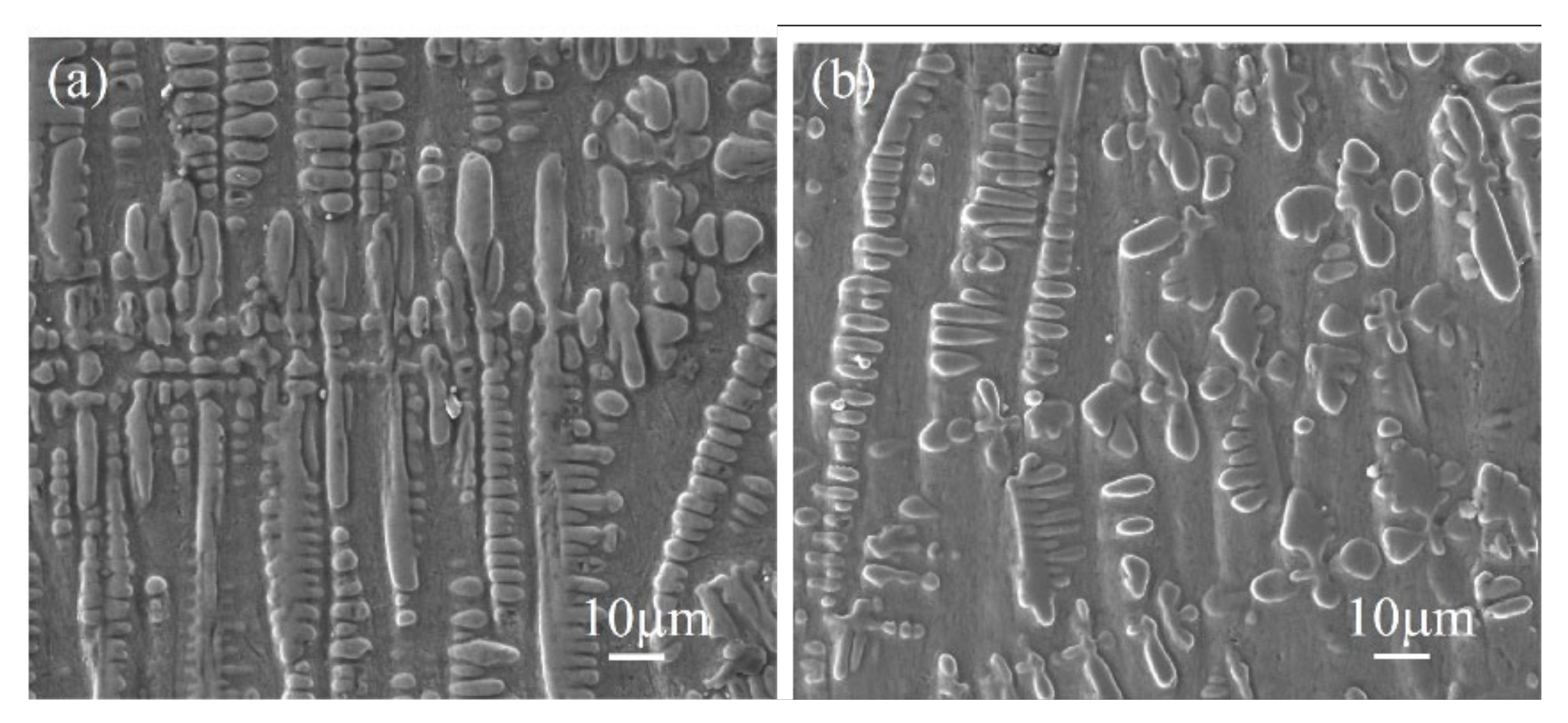
Figure 7 shows the SEM images of the nitrided layer in pure (100%) nitrogen atmosphere, and an atmosphere of 64% nitrogen and 36% argon. The nitrided layer showed different morphologies and sized dendrites as the nitrogen concentration changes, which then influenced the hardness value. The dendrites of the nitrided layer were denser and smaller in a pure 100% nitrogen atmosphere, than in the 64% nitrogen (36% argon) atmosphere. The hardness tended to increase as the dendrite density and size increased. Therefore, the area fraction, size, and morphology of the dendrites have a dominant influence on the hardness, which are all influenced by the gas atmosphere.
3.3. Microstructure of the Nitrided Layers
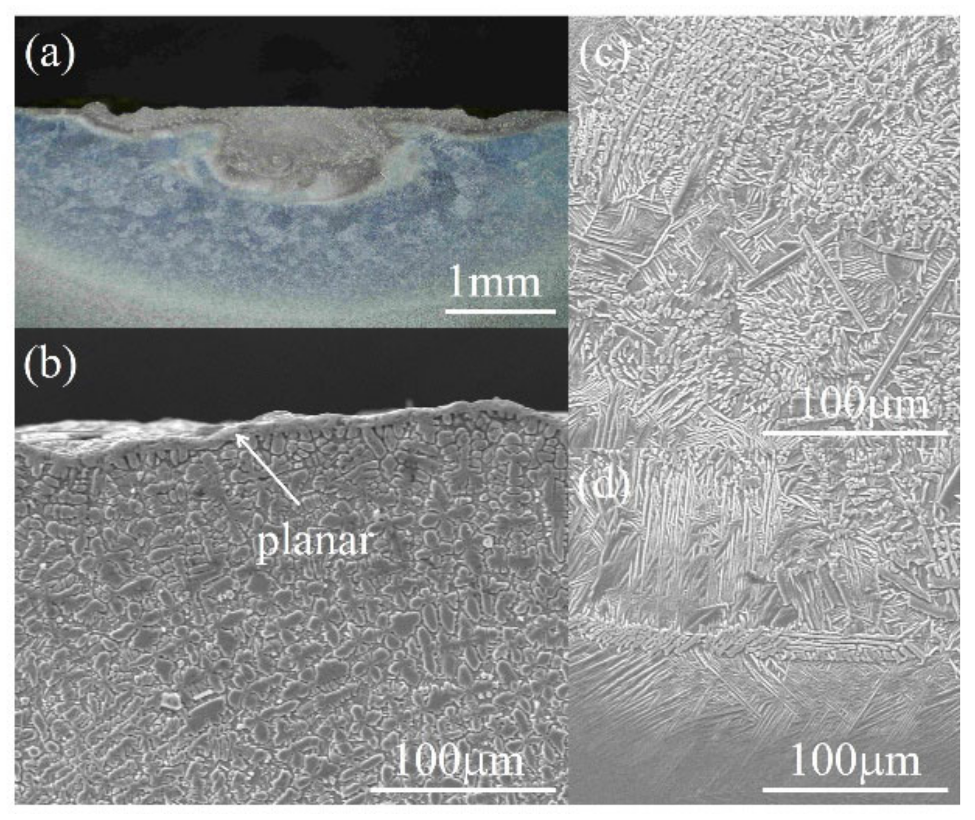
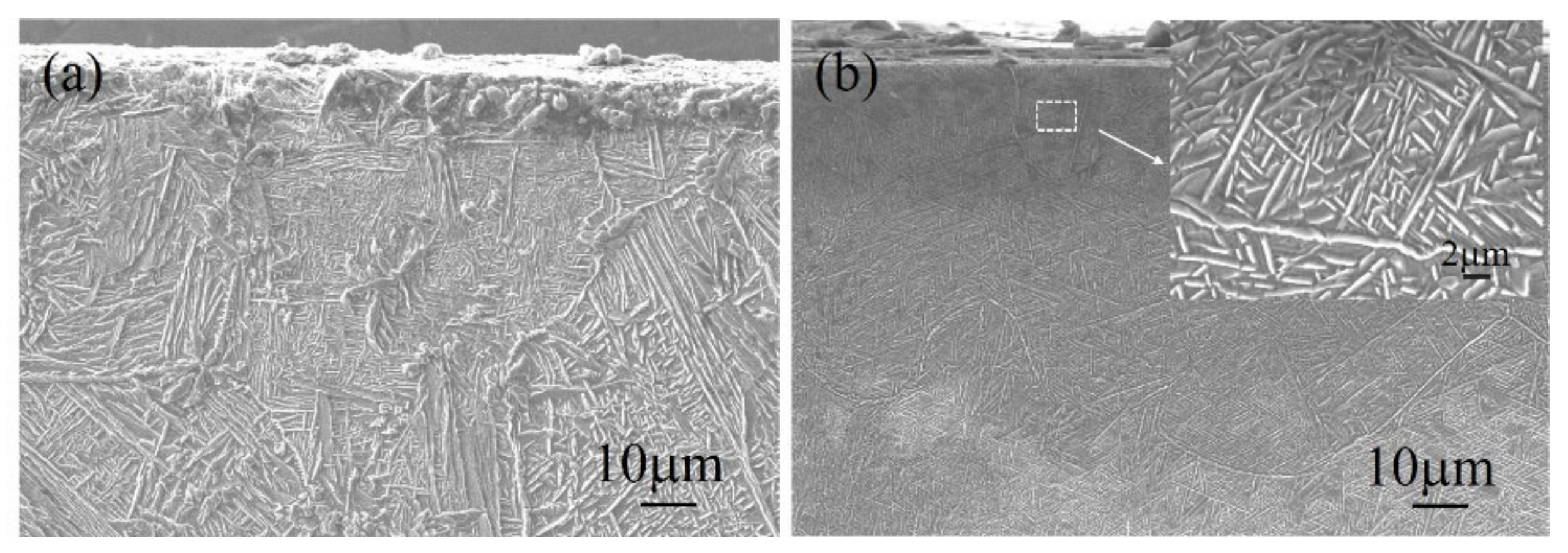
The fusion zone between the nitrided layer and the substrate was a completely metallurgical combination. The cross section of the nitrided sample consists of three parts: the nitrided layer, the heat-affected area, and the substrate (
Figure 8). The heat-affected zone (
Figure 8d) showed occasional acicular martensite. The nitrided layer was mainly composed of dendrites and acicular martensite in the pure (100%) nitrogen atmosphere. Then, as the nitrogen concentration of the nitrogen–argon atmosphere decreased, the dendrites in the nitrided layer reduced, and the amount of acicular martensite increased (
Figure 9). The nitrided layer was composed of the thin planar layer and acicular martensite in an atmosphere of 5% nitrogen and 95% argon (
Figure 9b). The thin planar layer only appeared on the surface of the nitrided layer in the diluted nitrogen atmosphere and not in a pure (100%) nitrogen atmosphere (not shown).
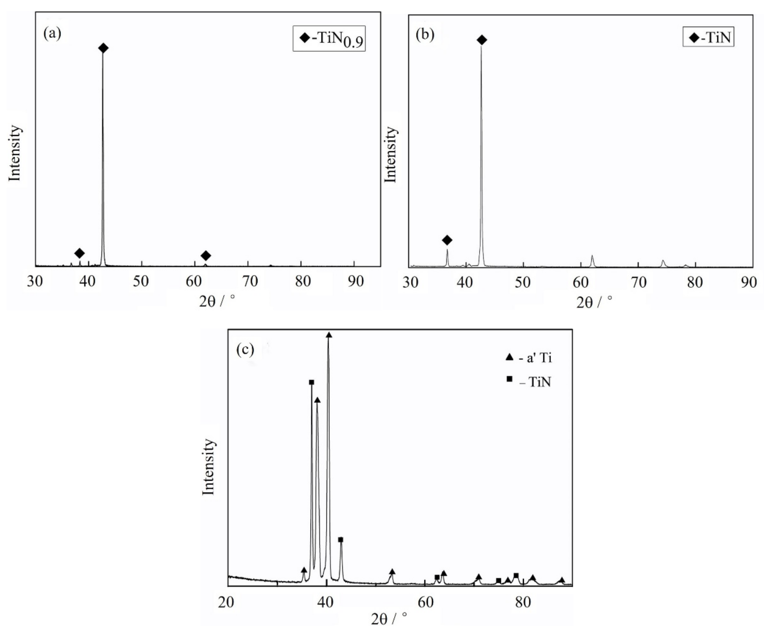
The surface XRD of the nitrided layer consisted of TiN
0.9 in a pure (100%) nitrogen atmosphere (
Figure 10a). Then, for the thin planar layer, only TiN appeared in the 80% nitrogen (20% argon) atmosphere (
Figure 10b). When the nitrogen concentration decreased further (5% nitrogen and 95% argon), the surface of the nitrided layers consisted of TiN and α’-Ti (
Figure 10c).
The orientation of dendrites (
Figure 8) was interesting, since the thermal gradient (
G) was highest on the surface of the molten pool, and then decreased with depth, which influences the value for
G/
R (where
R is radius of the molten pool). Thus, nitrogen absorbed into the molten pool caused the nitrogen concentration to be highest at the pool surface and then it decreased with depth (toward the bottom of the pool). Therefore, the surface reached the solubility limit for nitrogen in titanium more readily and solidified to form titanium nitride. Due to the nature of sub-cooling, the solidification front at the surface of the molten pool is not flat. There are solidifications that protrude, which lead to the development of dendrite structures. At the same time, another solidification front that is not nitrogen-rich proceeds from the bottom of the molten pool toward the surface, as observed by other authors [
16]. Therefore, solidification mainly occurred from a solid solution of nitrogen in titanium, which showed acicular martensite (
Figure 9).
Zhechena et al. [
17] built up a simplified physical diffusion model for the formation and growth of the nitrided layer by the laser gas nitriding of pure titanium. The addition of alloy elements may cause a deviation of phases for the Ti–6Al–4V alloy. However, other elements in the titanium alloy are small in quantity and are usually dissolved in hcp α-Ti by formation of a substitutional solid solution. Thus, dramatic changes to the kinetics of formation and the phase compositions of the nitrided layers in the titanium alloy are not likely.
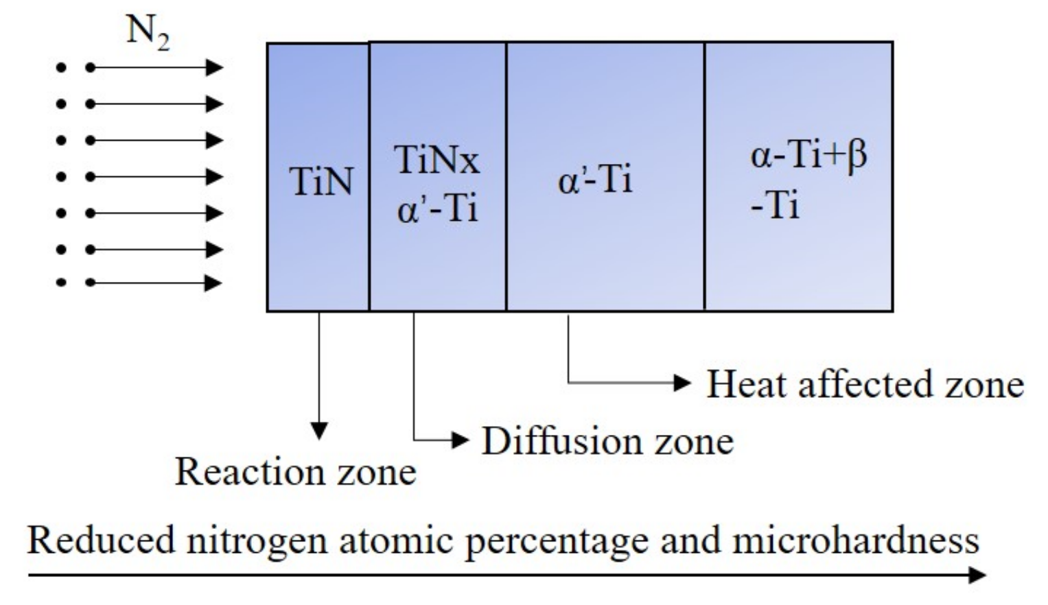
Based on the results of this work, and the conclusions of previous research on the microstructure and phase compositions of nitrided layers [
12,
15,
18,
19,
20], the phase distribution of layers can be predicted (
Figure 11). The XRD result of the nitrided surface illustrates that the thin planar layer on the surface was TiN, TiN
x was dendritic, and α’-Ti was acicular martensite, which may be a result of the β phase to martensitic α’-Ti transformation in a highly non-equilibrium condition. Phases in the nitrided layer may include hcp TiN
0.3 and Ti
2N, which form during the process of laser gas nitriding. The phase type also influences the hardness of the nitrided layer.
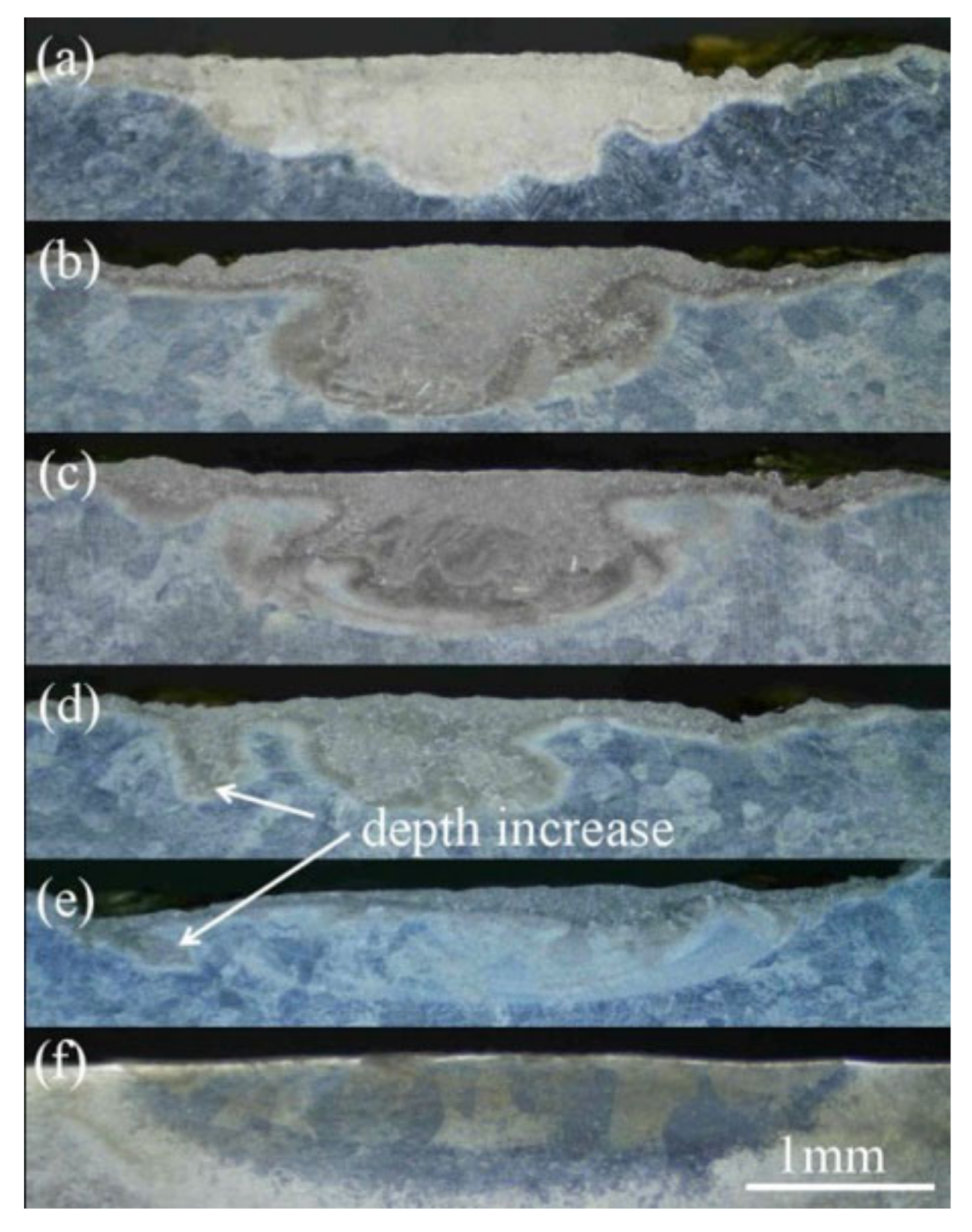
The Heiple surface tension model can be used to explain formations in the microimages, which result from the molten pool (
Figure 12). The surface tension gradient (with respect to temperature) of liquid titanium is negative, therefore shallow and wide molten pool formations are formed for the titanium alloy, and as previously observed [
21].
The micrographs of the cross section of stringer beads (
Figure 12) provide important information about the transport mechanism of nitrogen in the molten pool. When dendrites are produced in the nitrided layer, Marangoni convection dominates the molten pool dynamics in the pure (100%) nitrogen atmosphere. As argon is introduced into the gas flow, and the concentration of nitrogen is reduced, the fusion line becomes obscure (
Figure 12b–d). In an atmosphere of 18% nitrogen and 82% argon, dendrites are limited to a very thin surface layer, and the fusion line completely disappears (
Figure 12e). This shows that the transport mechanism of heat and mass changes from convection-dominated to diffusion-dominated when the nitrogen concentration decreases, and as observed by other authors [
21]. However, the nitrided layer was entirely composed of acicular martensite (except for the thin planar layer of the surface) when the nitrogen concentration (of the nitrogen–argon atmosphere) was 5%, and convection dominated the molten pool dynamics. The depth of the nitrided layer was significantly deepened for the 46% and 18% nitrogen concentration atmospheres, as shown by the arrows in
Figure 12d,e. This effect may have been caused by the annular nozzle used because the distance between the abrupt location of the molten depth and the center of the nitrided layer was equal to the radius of the annular nozzle, and the gas coming out of the annular nozzle deepened the depth of the molten pool.
3.4. Cracks of the Nitrided Layers
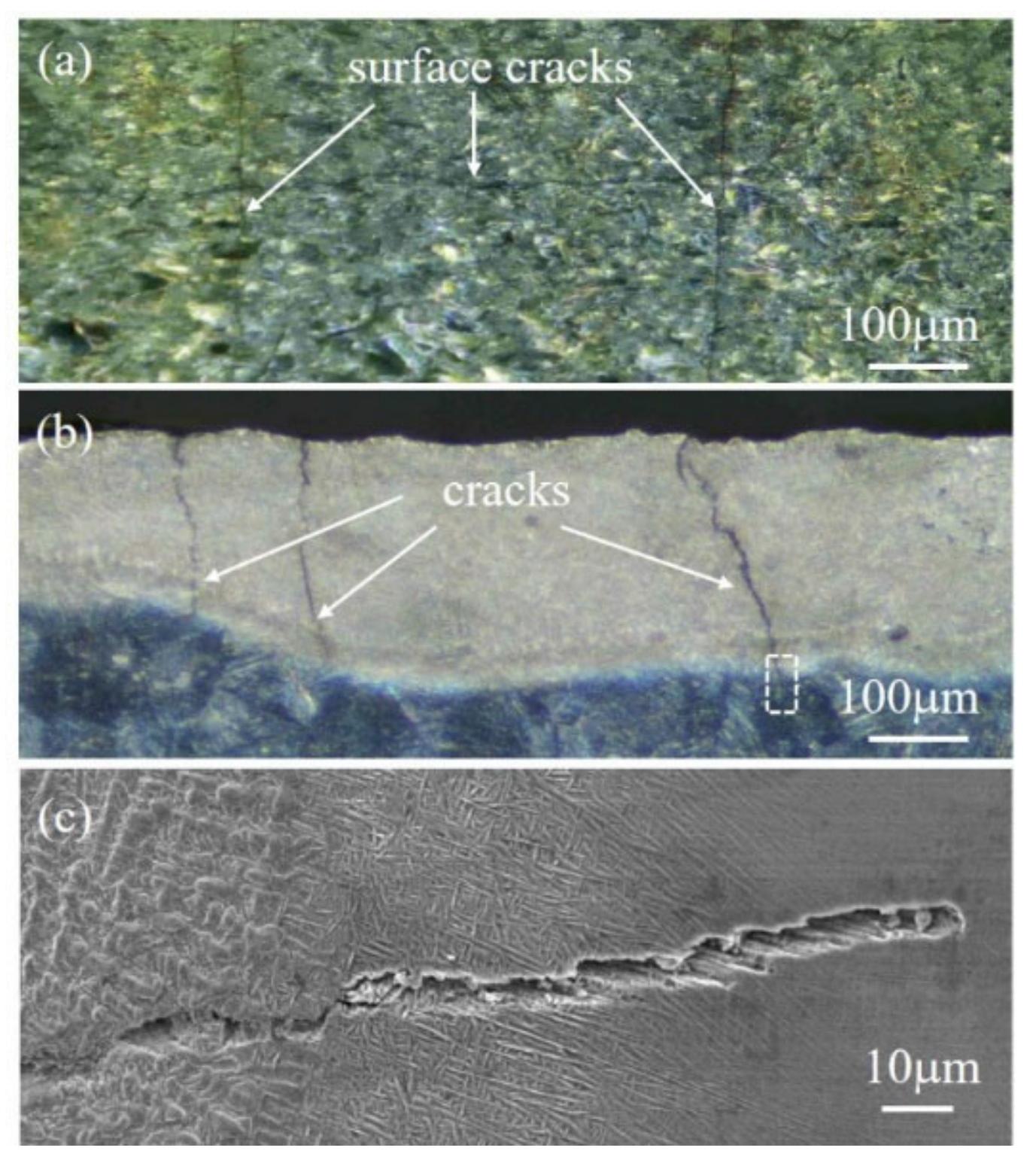
Longitudinal and transverse cracks were observed on the surface and the cross section of the nitrided layer in pure (100%) nitrogen (
Figure 13a). The transverse cracks were perpendicular to the scanning direction and were approximately parallel to each other; here, they dominated the surface of the nitrided layer. Longitudinal cracks propagated from the surface nitrided layers down though the lower layers, but were then stopped at the heat-affected zone (
Figure 13b,c). These cracks were not present in the overlapping tracks, which overlapped by 38%, under an atmosphere of 5% nitrogen and 95% argon (
Figure 9). Here, the microstructure was composed of acicular structures and a thin planar layer.
Due to intense local heating from the high-energy density diode laser, and the subsequent rapid cooling and addition of nitrogen, the laser nitriding process inevitably generates residual stress in the treated layer [
22]. The stress is mainly caused by thermal and microstructure stress, and cracks occur when local residual stress exceeds the strength limit of the material. Cracks in the cross section of the nitrided layer can also originate from the process of cutting specimens. Microcracks between the nitrided layers and the heat-affected zone may also be related to the inherent brittleness of titanium nitride [
23].


