Article

Influence of the Thickness of a Nanolayer Composite Coating on Values of Residual Stress and the Nature of Coating Wear

1
VTO Department, Moscow State Technological University STANKIN, Moscow 127994, Russia
2
Department of Theoretical Mechanics, Belarusian National Technical University, Minsk 220013, Belarus
3
Department of Solid State Physics and Nanosystems, National Research Nuclear University MEPhI, Moscow 115409, Russia
4
Baikov Institute of Metallurgy and Materials Science RAS, Moscow 119334, Russia
5
Institute of Design and Technology Informatics (IKTI) RAN, Moscow 127055, Russia
6
Central Research Institute of Machine Building Technology (PJSC SPA “CNIITMASH”), Moscow 115088, Russia
*
Author to whom correspondence should be addressed.
Coatings 2020, 10(1), 63; https://doi.org/10.3390/coatings10010063
Submission received: 12 November 2019 / Revised: 19 December 2019 / Accepted: 8 January 2020 / Published: 10 January 2020
(This article belongs to the Special Issue Stress in Thin Films and Coatings)

Abstract

:
The article discusses the influence of the thickness of the wear-resistant layer of the Zr-ZrN-(Zr,Al,Si)N nanolayer composite coating on the values of residual stress and the nature of coating wear. The study focused on coatings with wear-resistant layer thicknesses of 2.0, 4.3, 5.9, and 8.5 µm, deposited using filtered cathodic vacuum arc deposition (FCVAD) technology. The X-ray diffraction (XRD) method based on the anisotropy of the elasticity modulus was used to find the values of the residual stress. The nature of the formation of interlayer delamination under the influence of residual compressive stress was studied using a scanning electron microscope (SEM). When the wear-resistant layers had a thickness of 2.0–5.9 μm, tensile stress formed, which decreased with an increase in the thickness of the coating. When the thickness of a wear-resistant layer was 8.5 μm, compressive stress formed. Under the action of compressive stress, periodic interlayer delamination formed, with a pitch of about 10 binary nanolayers. A mathematical model is proposed to describe the nature of the formation of interlayer delamination under the influence of compressive residual stress, including in the presence of a microdroplet embedded in the coating structure.

1. Introduction

The internal residual stress that forms in coatings during their deposition has been a subject of research for a long time. Detailed analyses of the methods for studying stress in coatings and thin films are contained, in particular, in [1,2,3,4]. The measurement of stress in a coating with a thickness of only several micrometers, which includes various phases that differ in their properties, presents a certain challenge. The task is further complicated when it comes to coatings with nanolayer structures, including nanolayers of different phase compositions and mechanical properties. Meanwhile, residual stress has a significant effect on the functional properties of the coatings, their service life periods, and the reliability of the operation of coated products. In particular, cracks and interlayer delamination can form in the coatings, which leads to the destruction of the structure, to chipping, and to the loss of functional properties. Compressive stress usually leads to the formation of delamination and longitudinal cracks [5,6], whereas tensile stress leads to the formation of transverse cracks [7,8]. The distribution of residual stress in the coating affects both the adhesion to the substrate and the fracture toughness [9,10,11].
It is clear that the formation of residual stress is associated with the process of coating deposition. From this point of view, three models of coating deposition are usually considered: formation and merging of three-dimensional (3D) islets [12], layer-by-layer deposition [13], and a combined model that considers the formation of 3D islets on a thin wetting layer [14]. Various defects on the surface of the substrate (micropores, cracks, irregularities, dirt spots, etc.) [15,16,17,18,19,20,21] as well as defects in the coating itself (microdroplets, interlayer delamination, etc.) have a significant influence on the coating formation process [19,20,21].
Depending on the type of material, two models of the formation of residual stress during the coating deposition are usually considered: Model 1, in which only tensile stress forms (in particular, the model is typical for metals with a high melting point), and Model 2, in which both tensile stress (usually on the first stage of coating deposition) and compressive stress (typical for metals with a lower melting point) form [1,4]. Another source of residual stress is the processes of recrystallization, restructuring, and diffusion and the difference in the coefficients of thermal linear expansion of various coating layers [22,23].
Various methods are used to determine the stress in the coating structure [1,2,3,4]. A number of articles have focused on the studies of residual stress in the coatings of various compositions and thicknesses. Meanwhile, the sin2ψ X-ray diffraction (XRD) method is most often used to determine the strain components for research.
Djaziri et al. [24] studied residual stress in single-layer monolithic TiN and ZrN coatings with thicknesses of 1–2 μm. The data obtained using the XRD method and other techniques (optical method and laser curvature technique) were compared, and the comparison showed a high degree of similarity of the results. Singh et al. [25] studied the residual stress on Al-SiC nanocomposite coatings, depending on the number and thickness of the layers. The multilayer structure of the coating was found to lead to an increase in the compressive residual stress compared to a monolayer structure of the coating with the same thickness. Chason et al. [26] proposed a model to predict the formation of tensile or compressive stress depending on the grain sizes, growth rate, and diffusivity. In particular, for structures with smaller grain sizes, large compressive stress was typical, whereas tensile stress formed at higher grain growth rates, and compressive stress formed at lower grain growth rates.
Bielawski et al. [27] studied TiN-Si coatings with thicknesses in a range of 1–12 μm. They found that, with an increase in the thickness, the stress transforms from compressive (for coating thicknesses less than 3 μm) to tensile (for coating thicknesses of 3–12 μm), and a higher hardness of the coating is also associated with higher values of residual stress (the results contradict the results of some other studies). Li et al. [28] studied the residual stress of a nanocrystalline Cr2O3 coating. For the given coating, the value of the residual stress does not depend on the thickness of the coating when the thicknesses exceed 0.8 μm, but at smaller thicknesses, the appropriate relation takes place. Stress decreases with a decrease in coating thickness, but in all cases, only tensile stress registered. They also argued that such coating defects as microdroplets do not significantly affect the values of residual stress. The study revealed the influence of grain sizes on the nature of stress. In particular, in [29,30], with smaller grain sizes in the coating, the compressive stress increased. Meanwhile, the influence of grain sizes on the nature of residual stress is also associated with the grain growth rate [30].
A number of studies consider residual stress evolution in coatings (in particular, biaxial stress). Veprek et al. [31] note that due to high biaxial compressive stress, the hardness of the coating can increase significantly. Specific resistance decreased with an increase in biaxial stress, while Hall mobility and carrier concentration increased. Hwang et al. [32] found that specific electric resistance decreased with an increase in biaxial compressive stress, while Hall mobility and carrier concentration increased. In turn, residual stress is related to microstructural order in the coating structure. The results obtained by Tien et al. [33] show that residual stress and surface roughness are higher in the coatings on the samples that were located in the upper part of the chamber during the coating deposition process.
Thus, the analysis of the available studies shows that the distribution and values of residual stress depend on the chemical composition, thickness, and structure of the coating. During the formation of coatings with multilayer structures and small grain sizes, provided that the coating deposition rates (and the grain growth rate) are sufficiently low, significant compressive stress can occur with a large coating thickness. At the same time, such factors as small coating thicknesses, larger grain sizes, higher grain growth rates, and monolithic coating structures contribute to the formation of tensile stress. The purpose of the research was to study the influence of the coating thickness on the values of residual stress and to study the effect of residual stress on the nature of coating wear.

2. Materials and Methods
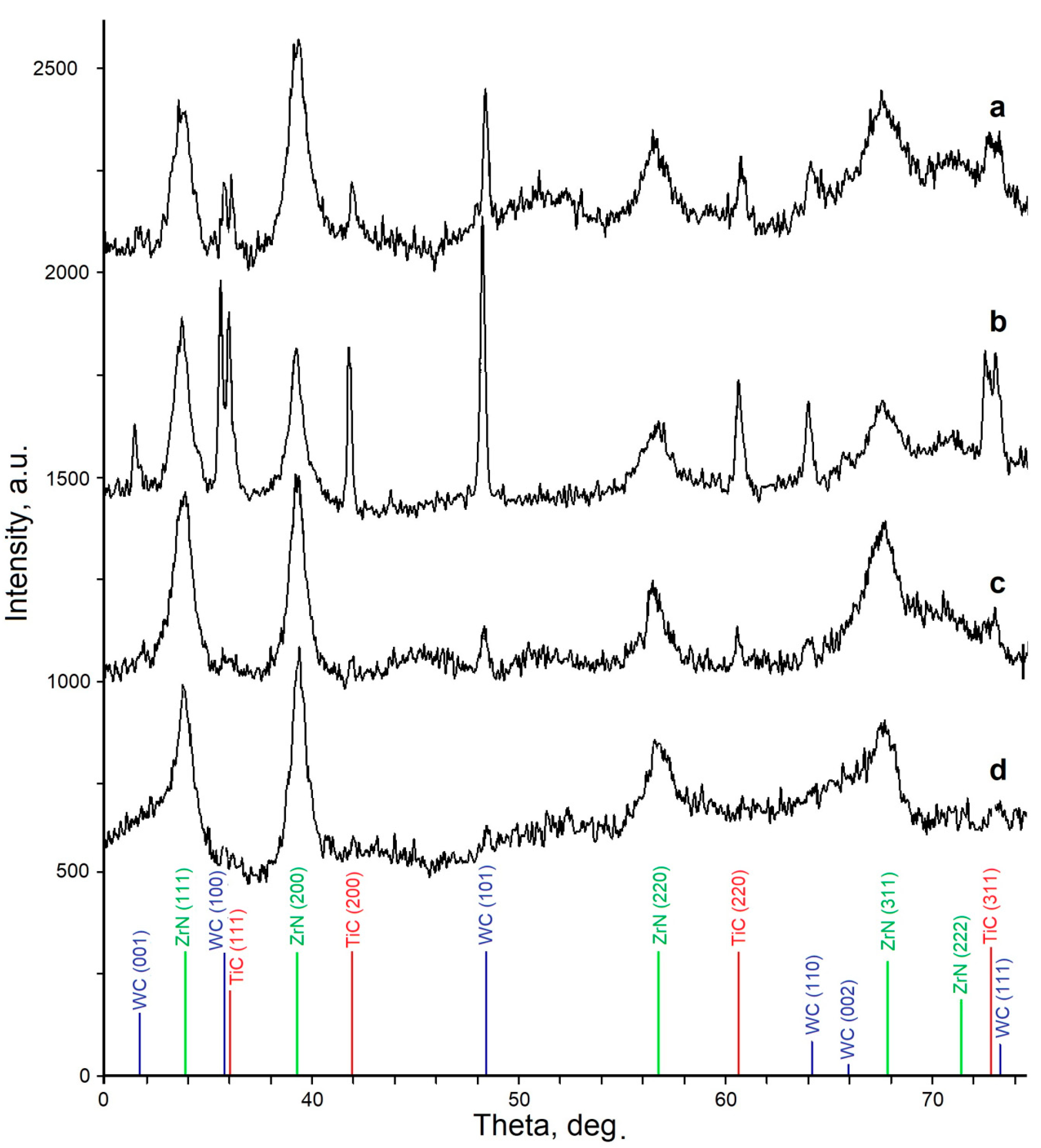
To study the relation between the values of residual stress and the thickness of the coating, four samples with the Zr-ZrN-(Zr,Al,Si)N coating were manufactured with different deposition times of the wear-resistant layers of the coating with a three-layer architecture [34,35,36,37]: 15, 30, 40, and 60 min. For the deposition of coatings, a vacuum-arc VIT-2 unit was used, which was designed for the synthesis of coatings on the substrates of various tool materials. The unit was equipped with an arc evaporator with filtration of vapor-ion flow (FCVAD) [34,35,37], which was used for the deposition of the coating on the tool to significantly reduce the formation of droplets during coating.
Prior to the deposition of the coatings, the samples were prepared as follows: initially, they were cleaned in an ultrasonic cleaner using special (environmentally friendly) detergent; then they were washed in running water, and finally in distilled water. The final cleaning of the sample surfaces was carried in the unit chamber, in a stream of gaseous plasma.
To deposit the coatings, cylindrical cathodes of the following compositions were used: Zr (99.98%) and (Al,Si) (92 at% + 8 at%; 99.96%). During the coating deposition process, 2 Zr cathodes and 1 (Al,Si) cathode were used simultaneously. The cathodes were installed in evaporators, located in one horizontal plane, and the central axes of the evaporators located at 90° to each other. The scheme of the cathode positions in VIT-2 unit and the scheme of the coating deposition process are presented in [34].
During the coating deposition, evaporators with microdroplet phase separation were used [34,35,37]. The parameters of the coating deposition are presented in Table 1.
For microstructural studies of samples of carbide substrates with coatings, a scanning electron microscope (SEM) FEI Quanta 600 FEG with energy-dispersive X-ray spectroscopy (EDS) was used. The studies of chemical composition were conducted using the same SEM. To perform the X-ray spectroscopy microanalysis, the study used characteristic X-ray emissions resulting from the electron bombardment of a sample.
The X-ray diffraction (XRD) analysis was performed on a PANalytical Empyrean diffractometer with CuKα radiation. To determine the residual stress in the coatings, the sin2ψ estimation method was used [38,39,40,41]. When determining the residual stress using the sin2ψ X-ray method, the lattice spacing d ψ hkl for the reflection (hkl) was measured at several values of the angle ψ. Meanwhile, the value ψ = 0 corresponds to the reflection from the planes (hkl) for grains in which the plane is parallel to the plane of the sample, and the values (ψ ≠ 0) correspond to the reflections from the grains in which the planes (hkl) are located at an angle ψ to the plane of the sample.
When the sin2ψ method was used, the lattice parameters were measured at the symmetric and inclined positions of the sample with respect to the incident and reflected beams. The value of the lattice deformation differs for grains with different orientations with respect to stress. The values of the stress were calculated using the difference in the deformation. In an asymmetric survey, the informative depth decreased with an increase in the angle ψ. In the case under consideration, the above led to the disappearance of the diffraction maxima from the coating due to a relatively small coating thickness. Therefore, to calculate the residual stress, a technique based on the anisotropy of the elasticity modulus was used [38,39]. Since the structure of the coating is anisotropic, a more comprehensive approach to the study of residual stress is required. In the case of a nanolayer coating, it is usually an alternation of nanolayers, each of which has a columnar structure [42,43,44,45,46]. For this purpose, the method of unequal biaxial stress states proposed in [40,41] was used. According to the equipment manufacture, the allowance in measurements aimed to locate the centre of gravity of diffraction maximum is ±0.0001, which, when calculating the stress with the method used, corresponds to the allowance of ±3 MPa.
The hardness (HV) of coatings was determined by measuring the indentation at low loads according to the method by Oliver and Pharr [47]. This was carried out on a microindentometer microhardness tester (CSM Instruments) at a fixed load of 10 mN. For each sample, 20 microhardness measurements were carried out, the two lowest and two highest values were ignored, and then the average value was determined.

3. Results

3.1. Influence of the Coating Thickness on the Values and Nature of Residual Stress

Figure 1 shows cross sections of the coated samples under study. For Samples 1–4, the thicknesses of the wear-resistant layers are about 2.0, 4.3, 5.9, and 8.5 µm, respectively.
Table 2 presents the microhardness values of the coated samples under study.
All the samples under study have very close, almost equal microhardness values, and that fact correlates with the data, earlier obtained for the (Ti,Al,Si)N coating [37], and proves that the deposition time (and, correspondingly, thickness) does not significantly affect the hardness of the coating.
Figure 2 presents the diffraction patterns of the coatings for Samples 1–4 under study.
The table with the values of the lattice periods and stress calculated for the reflections characterized by elastic constants and, accordingly, different lattice deformation under the action of residual stress can be found below (Table 3).
The data for the directions X and Y are presented in Figure 3 in a generalized graphical form.
Based on the obtained data, the calculations were run and a relation was found between the values of residual stress and the time of deposition of the Zr-ZrN-(Zr,Al,Si)N coating on a substrate of (WC + TiC) carbide (i.e., the thickness of the coating; Figure 4). The used Young’s modulus values for various crystallographic directions of ZrN are presented in Table 4.
Several studies carried out earlier (particularly [48,49]) show that tensile stress formed in the layers immediately adjacent to the substrate, whereas compressive stress in the layers is remote from the substrate. Following the analysis of the information presented in Figure 4, starting from the initial stage of the coating deposition to a certain point, high tensile stress formed, which is a natural result of the coating deposition on a substrate with a significantly lower coefficient of thermal expansion (CTE) compared to the coating itself. If for a carbide (WC + Co) substrate, CTE is 5.7–6.7 × 10⁻⁶K−1 [50], then for a coating, this value reaches 8.12–14 × 10−6K−1 [51,52].
The values of the stress (σtens) can be defined using the following well-known relation [53]:
Σtens = Ecoat − αsubs)∆T,
where E is the Young’s modulus of the coating, αcoat and αsubs are the coefficients of thermal linear expansion of the coating and the substrate, respectively, and ∆T is the temperature difference between the deposited coating and environment.
Another important reason for the formation of tensile stress is the beginning of merging during the initial deposition of the coating when individual islets start to collide and form grain boundaries [54,55].
Furthermore, from the substrate and layers deposited earlier, the coating layer being deposited is subjected to compressive stress caused by the mechanical action of positively charged ions bombarding the surface, possessing high kinetic energy due to the negative potential on the substrate (σcomp) [56,57]. The effect is similar to that of bead blasting on the surface, when compression along the normal of the surface of the substrate and the extension in its plane occur, which is inhibited by the subsurface layers of the substrate and the coating layers deposited earlier that create compressive stress in the surface layers. Another factor affecting the formation of compressive residual stress is the fact that the temperature of the nanolayer being deposited is higher than the temperature of the nanolayer deposited earlier. The deposited nanolayer begins to become cold and compresses. The values of compressive residual stress gradually increase during the deposition of each new layer until the compressive force exceeds the strength of the cohesive bond between the nanolayers and an interlayer delamination forms. In turn, that will lead to the release of compressive stress that again increases when subsequent layers are deposited. Therefore, in nanolayer coatings of large thicknesses, the formation of periodically repeating interlayer delamination can be predicted.
Thus, the total stress comprises two components:
σres = σtens + σcomp.
As the coating thickness increases, the contribution of σtens to the total stress decreases, whereas in contrast, the portion of σcomp increases, which explains the relation between the values of residual stress and the time of deposition and thickness of the coating (Figure 5).
In [13], the relation between the values of internal stress and the time of coating deposition is described as follows:
d ( σ ¯ h ) d h = σ x x ( h ) d h d t + 0 h σ x x ( z ) t d z ,
where h is the thickness of the coating at time t, σ x x ( h ) d h d t determines the effect on the stress of the deposition of a new layer, and 0 h σ x x ( z ) t d z determines the change in the stress in the layers deposited earlier. In some studies, the value is assumed to be zero (i.e., it is assumed that the stress in the layers already deposited does not change during the deposition of subsequent layers), then it is possible to obtain the following relation to determine the stress depending on the coating thickness [13]:
σ x x ( h ) = d ( σ ¯ h ) d t d h d t = d ( σ ¯ h ) d h .
The studies show [1,4] that the value of 0 h σ x x ( z ) t d z is not equal to zero (i.e., the stress in the deposited coating layers continues to change after deposition). Such a change in the stress can be associated with various processes that continue to occur in the coating layers after their deposition: diffusion, phase transformations, grain growth, and uneven cooling of various layers.

3.2. Influence of Compressive Residual Stress and Internal Defects in Coatings of Large Thicknesses on the Formation of Interlayer Delamination

At a coating thickness of 8 μm, residual compressive stress of sufficiently high intensity forms in the coating structure. It is possible to find how stress affects the structure of the coating. Figure 5 shows the consideration of the formation of delamination in a coating of large thickness. Four subsequent delamination layers are shown, and there was a certain periodicity in their formation (about 10 binary nanolayers). An important point is the difference in the nature of the observed delamination, which can be associated with an increase in the value of compressive stress as the thickness of the coating increases. In particular, in Area A, located close to the substrate, only delamination was noticed, and the nanolayer structure of the coating was not violated (Figure 5a). As the coating thickness grew, the compressive stress increased, and in Area B, not only delamination but also transverse cracks through the coating nanolayers formed (Figure 5b). Finally, in Area C, located near the external surface of the coating, along with the delamination between the nanolayers, an expanding crack also formed, which destroyed the coating structure. Meanwhile, the width of the delamination itself increased and reached a thickness of 2–3 binary nanolayers (Figure 5d).
A significant effect on the nature of coating destruction under the influence of compressive stress is produced by various internal defects in the coating, in particular, microdroplets embedded in the coating structure. Figure 6a shows how delamination occurs, under the influence of a microdroplet embedded in the coating structure, transforming into a through-transverse crack. The mechanism of such a transformation was considered below. The structure of the cracks and delamination under consideration clearly reduced the strength of the coating and could lead to its early destruction during operation. In the area of the same coating, in the absence of internal defects, a sequence of delamination layers was formed without any transverse cracks (Figure 6b). In particular, in Area A, a nanolayer of the coating bends under the influence of compressive stress, and as a result, the cohesive bonds between adjacent nanolayers failed, and delamination formed.

4. Discussion

Under certain conditions, the internal compressive stress leads to the formation of not only delamination and longitudinal cracks but also transverse cracks. For a better understanding of the reasons for the formation of the structure described above, the process of coating deposition was considered, in which a layer cooled down with a liquid droplet inside. Since the layer thickness was much larger than the droplet, it could be assumed that the droplet is in unbounded space. The stress–strain state is the same in any diametric section of a droplet in a vertical plane, so we considered the challenge in a cylindrical coordinate system for the environment outside of the sphere (droplet) and in a spherical coordinate system in a sphere (droplet). A droplet has an initial temperature T s p ° . We singled out three zones (Figure 7): (1) a spherical droplet, (2) an outer spherical layer with broken lamination, and (3) a nanolayer environment (Figure 7).
We considered the cooling of a droplet in Zone 1 under a linear time cooling regime. Temperature Tκ at an arbitrary point M in Zone 1 is defined by the following equation:
T 1 t = h 1 2 2 T 1 = h 1 2 r 2 r 2 ( r T 1 ) .
Through a Laplace transform (5) on time with allowance for the initial condition, we obtained the auxiliary (transformed) equation:
q 1 2 r T ˜ 1 = 2 r 2 ( r T ˜ 1 ) ,   h 1 2 = k 1 ρ 1 c 1 ,   p = h 1 2 q 2 .
It is assumed that Tc(o) is the temperature surrounding a droplet at the initial time point T1(o) = T2(o), where c1 is the specific heat absorption capacity for the droplet, ρ1 is the density, k1 is the thermal conductivity coefficient, h 1 2 is the temperature conductivity coefficient, and p is the argument of the Laplace transform. The solution of Equation (6), limited to the droplet centre, is given by the following:
T 1 = r · s h q r .
Suppose that temperature at the outer boundary of the spherical layer (6) varies linearly with time T2 = Gt, where G is a constant. The boundary condition on the droplet surface is given by the following:
T 1 r = K ( G t T 1 ) .
Here, K depends on the ratio of thermal conductivities of Layers (1) and (2) and on the thickness of Layer (2). Suppose that a droplet radius is equal to a = R1, then we have the following:
A = a 2 K G / p K a s h q a + q a c h q a s h q a .
The average Laplace transform for the droplet temperature by volume is calculated from the following formula:
< T ˜ 1 > = 3 a 2 0 a r 2 T 1 d r = 3 A a 2 0 a r s h q r d r = 3 K G a p q 2 q a s h q a s h q a K a s h q a + q a s h q a s h q a .
For small q, the approximate principal value for (10) has the following form:
< T ˜ 1 > 3 K G a p q 2 ( q a ) 3 ( 1 3 + 1 30 q 2 a 2 ) q a ( K a + 1 6 K q 2 a 2 + 1 3 q 2 a 2 ) = G { 1 p ( 1 15 a 2 h 2 + 1 3 a h 2 K ) } .
The average temperature change in a droplet in time is obtained by applying the inverse Laplace transform to (11). Then, we obtained the following:
< T 1 > = G { t a 2 h 2 ( 1 15 + 1 3 a K ) } .
Equation (12) shows that the temperature reduction in Zone 1 lags the temperature drop in Zone 3 because of the screening effect of Zone 2. More accurate calculations yield corrections that decrease exponentially with time. Thus, the droplet may still be in the liquid state, and the coating layers have already crystallized, so the lag in cooling leads to the formation of a concentration of residual stress in Zone 2. They can reach the limiting values with the formation of plastic zones, which are centers for crack formation.
We calculated the residual stress and deformation in Zones 1 and 2 upon cooling. The equilibrium equations in the spherical coordinate system are as follows:
d σ r r ( i ) d r + 2 ( σ r r ( i ) σ φ φ ( i ) ) r = 0 ,   ( i = 1 ,   2 ) ,
where index i assumes the value of 1 for Zone 1 and the value of 2 for Zone 2. Here, Equation (13) is written in dimensionless form:
r = R R 1 ,   u = U R 1 ,   σ i j ( i ) = T i j ( i ) C r r ( i ) ,
where R is the dimensional radius of the considered point N, U is the shift, Tij is the stress, and Crr is the radial elasticity modulus. At the border of Zone 1, we have the following:
u ( 1 ) = u ( 2 ) ,   γ σ r r ( 1 ) = σ r r ( 2 ) ,   0 γ 1 .
If ∆T is the change in temperature from initial T0 up to T, then the stress in the droplet material is as follows:
σ r r ( 1 ) = d u ( 1 ) d r k r ( 1 ) Δ T ( 1 ) + 2 β ( 1 ) ( u ( 1 ) r k φ Δ T ( 1 ) ) , σ φ φ ( 1 ) = β ( 1 ) d u ( 1 ) d r + ( λ ( 1 ) + β ( 1 ) ) u ( 1 ) r Δ T [ β ( 1 ) k r ( 1 ) + ( λ ( 1 ) + β ( 1 ) ) k φ ( 1 ) ] ,
λ ( 1 ) = c φ φ ( 1 ) + c r r ( 1 ) c r φ ( 1 ) c r r ( 1 ) ,   β ( 1 ) = c r φ ( 1 ) c r r ( 1 ) ,
where, in the general case, the coefficients of thermal conductivity in the radial direction kr and in the direction of the circle kφ are considered different. For an isotropic droplet, k r ( 1 ) = k φ ( 1 ) . Moreover, in the case of anisotropy, radial Crr, circumferential cφφ, and shear c modules are different. By substituting (16) and (17) into (13), we obtained an equation of displacements, the solution of which has the following form:
u ( 1 ) = w r Δ T ( 1 ) + A r s 1 ,   w = 2 c ( s 2 s 1 ) ( 1 s 1 ) , c = ( 1 β ( 1 ) ) k r ( 1 ) ( λ β ( 1 ) ) k θ ( 1 ) ,
{ s 1 s 2 } = 1 ± 1 + 8 λ 2 .
Similarly, for Zone 2, we obtained the following:
u ( 2 ) = k ( 2 ) Δ T r + D [ 2 ( 1 2 β ( 2 ) ) 1 + 2 β ( 2 ) c f r + 1 r 2 ] .
σ r r ( 2 ) = 2 ( 1 2 β ( 2 ) ) D ( c f 1 r 3 ) .
Random constants A and D are found from the coupling conditions of Zones 1 and 2 in the form of (11). With a sharp drop in temperature, it is possible that, for stress in Zone 2, the von Mises or Tresk’s condition of plasticity [58,59] is met:
σ φ φ ( 2 ) σ r r ( 2 ) = λ K ,
where the limit of plasticity K is as follows:
K ( 2 ) = K 0 ( 2 ) ( 1 r 3 Δ T ( 2 ) ) ,
where λ = 1 if σ r r ( 2 ) < 0 and λ = −1 if σ r r ( 2 ) > 0 . Here, K 0 ( 2 ) is the dimensionless coefficient of plasticity K 0 ( 2 ) = ϰ 0 ( 2 ) / c r r ( 2 ) at the initial temperature, and r3 characterizes the linearity of plastic softening (hardening) of the material depending on change in temperature. In plastic Zone 2, we have the following:
d σ r r ( 2 ) d r = 2 λ K ξ .
For 1 < r < ξ, the stress is the following:
σ r r ( 2 ) = 2 3 λ K ξ 3 ( c f 1 r 3 ) ,
where ξ = r the boundary of the plastic zone. The value cf is defined from the following condition:
σ r r ( 1 ) | f o r   r   =   c f 1 / 3 = 0 .
The result indicates the possibility of the appearance of a plastic zone almost symmetrically around a droplet. However, due to anisotropy, plastic zones will be distributed by separate clusters, which are centers in the formation of a crack.
We considered a model for the failure of a nanolayer structure above a droplet (1, Figure 8) that has fallen on the substrate (4). The qualitative process-flow diagram assumes that a droplet, when it hits the substrate, does not splatter but deforms and takes the form of a half ellipsoid. Further deposition of the material leads to the formation of a nanolayer arch (2) above the droplet. Near the droplet and arch, a medium (3) with longitudinal nanolayers is formed.
In this medium, cooling and crystallization go faster than in a droplet. Heat from the droplet rises upwards and maintains the temperature in the cylindrical volume (2) above the surrounding medium, which helps to bend the layers with convexity upwards. With further cooling, residual stress appears, applied from the side of a cooling droplet and compressing stress occurs from the side of the nanolayer coating, which contributes to the occurrence of delamination in the thickness of the nanolayers in the volume of the cylinder. The cross section of a droplet in a nanolayer medium is shown in Figure 8.
Thus, a microdroplet embedded into the structure of the coating during its deposition interacts with its structure when the coating cools down. Due to the above, compressive stress occurs, which, in turn, leads to the formation of delamination between nanolayers. If the above stress exceeds a certain value, the nanolayer arch is destroyed and a transverse crack is formed, an example of which is shown in Figure 6. The formation of such structures is typical for sufficiently thick coatings since, based on the initial conditions, the coating thickness should significantly exceed the size of an embedded droplet.

5. Conclusions

The article discussed the Zr-ZrN-(Zr,Al,Si)N coating with wear-resistant layer thicknesses of about 2.0, 4.3, 5.9, and 8.5 μm. The investigations of residual stress in the samples under study showed that, for coatings with wear-resistant layer thicknesses of 2.0–5.9 μm, the tensile stress was typical, which decreased as the thickness of the wear-resistant layer increased. For coatings with a wear-resistant layer thickness of 8.5 μm, sufficiently high intensity compressive stress was typical. The above result (the presence of residual compressive stress) in the latter coating is confirmed during the investigation of the formed sequences of interlayer delamination in the coating structure. The presence in the coating structure of additional stress concentrators (for example, an embedded microdroplet) in combination with a high level of compressive stress can lead to the formation of a transverse crack and destruction of the coating, which is also confirmed by the data on the appropriate mathematical model.

Author Contributions

Conceptualization, A.V., M.V. and A.C.; methodology, A.V., N.S. and A.A.; validation, D.L., C.S. and J.B.; formal analysis, A.C. and D.L.; investigation, N.S., A.A. and D.L.; data curation, D.L.; writing—original draft preparation, A.V.; supervision, A.V.; project administration, A.V. All authors have read and agreed to the published version of the manuscript.

Funding

This research was funded by Ministry of Education and Science of Russia, grant number 9.1372.2017/4.6.

Conflicts of Interest

The authors declare no conflict of interest.

References

  1. Abadias, G.; Chason, E.; Keckes, J.; Sebastiani, M.; Thompson, G.B.; Barthel, E.; Doll, G.L.; Murray, C.E.; Stoessel, C.H.; Martinu, L. Review Article: Stress in thin films and coatings: Current status, challenges, and prospects. J. Vac. Sci. Technol. A 2018, 36, 020801. [Google Scholar] [CrossRef] [Green Version]
  2. Soroka, O.B. Evaluation of residual stresses in PVD-coatings. Part 1. Review. Strength Mater. 2010, 42, 287–296. [Google Scholar] [CrossRef]
  3. Soroka, O.B.; Klymenko, S.A.; Kopeikina, M.Y. Evaluation of residual stresses in PVD-coatings. Part 2. Strength Mater. 2010, 42, 450–458. [Google Scholar] [CrossRef]
  4. Koch, R. Stress in Evaporated and Sputtered Thin Films—A Comparison. Surf. Coat. Technol. 2010, 204, 1973–1982. [Google Scholar] [CrossRef]
  5. George, M.; Coupeau, C.; Colin, J.; Grilhe, J. Mechanical behaviour of metallic thin films on polymeric substrates and the effect of ion beam assistance on crack propagation. Acta Mater. 2005, 53, 411–417. [Google Scholar] [CrossRef]
  6. Marx, V.M.; Toth, F.; Wiesinger, A.; Berger, J.; Kirchlechner, C.; Cordill, M.J.; Fischer, F.D.; Rammerstorfer, F.G.; Dehm, G. The influence of a brittle Cr interlayer on the deformation behavior of thin Cu films on flexible substrates: Experiment and mode. Acta Mater. 2015, 89, 278–289. [Google Scholar] [CrossRef] [Green Version]
  7. Coupeau, C. Atomic force microscopy study of the morphological shape of thin film buckling. Thin Solid Films 2002, 406, 190–194. [Google Scholar] [CrossRef]
  8. Moon, M.W.; Chung, J.W.; Lee, K.R.; Oh, K.H.; Wang, R.; Evans, A.G. An experimental study of the influence of imperfections on the buckling of compressed thin films. Acta Mater. 2002, 50, 1219–1227. [Google Scholar] [CrossRef]
  9. Bemporad, E.; Sebastiani, M.; Casadei, F.; Carassiti, F. Modelling, production and characterisation of duplex coatings (HVOF and PVD) on Ti-6Al-4V substrate for specific mechanical applications. Surf. Coat. Technol. 2007, 201, 7652–7662. [Google Scholar] [CrossRef]
  10. Schmidt, S.; Hanninen, T.; Wissting, J.; Hultman, L.; Goebbels, N.; Santana, A.; Tobler, M.; Hogberg, H. SiNx coatings deposited by reactive high power impulse magnetron sputtering: Process parameters influencing the residual coating stress. J. Appl. Phys. 2017, 121, 171904. [Google Scholar] [CrossRef] [Green Version]
  11. Chang, J.Y.; Yu, G.P.; Huang, J.H. Determination of Young’s modulus and Poisson’s ratio of thin films by combining 2 sin ψ X-ray diffraction and laser curvature methods. Thin Solid Films 2009, 517, 6759–6766. [Google Scholar] [CrossRef]
  12. Volmer, M.; Weber, A. Crystallization of Curcumin and Cinnamic Acid from Aqueous Solutions of Hydrotropes. Z. Phys. Chem. 1926, 119, 277–301. [Google Scholar]
  13. Frank, F.C.; van der Merwe, J.H. One-dimensional dislocations. I. Static theory. Proc. R. Soc. A 1949, 198, 205–216. [Google Scholar]
  14. Stranski, I.N.; Krastanow, L. Zur theorie der orientierten ausscheidung von ionenkristallen aufeinander. Mon. Chem. 1937, 71, 351–364. [Google Scholar] [CrossRef]
  15. Grigoriev, S.N.; Metel, A.S.; Fedorov, S.V. Modification of the structure and properties of high-speed steel by combined vacuum-plasma treatment. Met. Sci. Heat Treat. 2012, 54, 8–12. [Google Scholar] [CrossRef]
  16. Sobol, O.V.; Andreev, A.A.; Grigoriev, S.N.; Volosova, M.A.; Gorban, V.F. Vacuum-arc multilayer nanostructured TiN/Ti coatings: Structure, stress state, properties. Met. Sci. Heat Treat. 2012, 54, 28–33. [Google Scholar] [CrossRef]
  17. Metel, A.; Grigoriev, S.; Melnik, Y.; Panin, V.; Prudnikov, V. Cutting Tools Nitriding in Plasma Produced by a Fast Neutral Molecule Beam. Jpn. J. Appl. Phys. 2011, 50, 08JG04. [Google Scholar] [CrossRef]
  18. Grigoriev, S.N.; Melnik, Y.A.; Metel, A.S.; Panin, V.V. A Compact Vapor Source of Conductive Target Material Sputtered by 3-keV Ions at 0.05-Pa Pressure. Instrum. Exp. Tech. 2009, 52, 731–737. [Google Scholar] [CrossRef]
  19. Fominski, V.Y.; Grigoriev, S.N.; Celis, J.P.; Romanov, R.I.; Oshurko, V.B. Structure and mechanical properties of W-Se-C/diamond-like carbon and W-Se/diamond-like carbon bi-layer coatings prepared by pulsed laser deposition. Thin Solid Films 2012, 520, 6476–6483. [Google Scholar] [CrossRef]
  20. Vereschaka, A.S.; Grigoriev, S.N.; Tabakov, V.P.; Sotova, E.S.; Vereschaka, A.A.; Kulikov, M.Y. Improving the efficiency of the cutting tool made of ceramic when machining hardened steel by applying nano-dispersed multi-layered coatings. Key Eng. Mater. 2014, 581, 68–73. [Google Scholar] [CrossRef]
  21. Vereschaka, A.A.; Vereschaka, A.S.; Grigoriev, S.N.; Kirillov, A.K.; Khaustova, O.U. Development and research of environmentally friendly dry technological machining system with compensation of physical function of cutting fluids. Procedia CIRP 2013, 7, 311–316. [Google Scholar] [CrossRef] [Green Version]
  22. Chaudhari, P. Grain growth and stress relief in thin films. J. Vac. Sci. Technol. 1972, 9, 520–522. [Google Scholar] [CrossRef]
  23. Koch, R.; Abermann, R. Microstructural changes in vapour-deposited silver, copper and gold films investigated by internal stress measurements. Thin Solid Films 1986, 140, 217–226. [Google Scholar] [CrossRef]
  24. Djaziri, S.; Renault, P.-O.; Le Bourhis, E.; Goudeau, P.; Faurie, D.; Geandier, G.; Mocuta, C.; Thiaudière, D. Comparative study of the mechanical properties of nanostructured thin films on stretchable substrates. J. Appl. Phys. 2014, 116, 093504. [Google Scholar] [CrossRef]
  25. Singh, D.R.P.; Deng, X.; Chawla, N.; Hubbard, C.; Tang, G.; Shen, Y.-L. Residual stress characterization of Al/SiCnanoscale multilayers using X-ray synchrotron radiation. Thin Solid Films 2010, 519, 759–765. [Google Scholar] [CrossRef]
  26. Chason, E. A kinetic analysis of residual stress evolution in polycrystalline thin films. Thin Solid Films 2012, 526, 1–14. [Google Scholar] [CrossRef]
  27. Bielawski, M. Residual stress control in TiN/Si coatings deposited by unbalanced magnetron sputtering. Surf. Coat. Technol. 2006, 200, 3987–3995. [Google Scholar] [CrossRef]
  28. Li, Q.; Gou, Y.; Wang, T.G.; Gu, T.; Yu, Q.; Wang, L. Study on Local Residual Stress in a Nanocrystalline Cr O Coating byMicro-Raman Spectroscopy. Coatings 2019, 9, 500. [Google Scholar] [CrossRef] [Green Version]
  29. Koch, R.; Hu, D.; Das, A.K. Compressive stress in polycrystalline Volmer-Weber films. Phys. Rev. Lett. 2005, 94, 146101. [Google Scholar] [CrossRef] [Green Version]
  30. Engwall, A.M.; Rao, Z.; Chason, E. Origins of residual stress in thin films: Interaction between microstructure and growth kinetics. Mater. Des. 2016, 110, 616–623. [Google Scholar] [CrossRef] [Green Version]
  31. Veprek, S.; Karvankova, P.; Prochazka, J.; Männling, H. Different mechanisms leading to superhard coatings: Stable nanocomposites and high biaxial compressive stress. Mater. Res. Soc. Symp. Proc. 2002, 697, 27–32. [Google Scholar] [CrossRef]
  32. Hwang, Y.; Ahn, H.; Kang, M.; Um, Y. The effects of thermally-induced biaxial stress on the structural, electrical, and optical properties of Cu2O thin films. Curr. Appl. Phys. 2015, 15, S89–S94. [Google Scholar] [CrossRef]
  33. Tien, C.-L. Biaxial stresses, surface roughness and microstructure in evaporated TiO2 films with different deposition geometries. Appl. Surf. Sci. 2009, 256, 870–875. [Google Scholar] [CrossRef]
  34. Vereschaka, A.A.; Grigoriev, S.N.; Sitnikov, N.N.; Oganyan, G.V.; Batako, A. Working efficiency of cutting tools with multilayer nano-structured Ti–TiCN–(Ti,Al)CN and Ti–TiCN–(Ti,Al,Cr)CN coatings: Analysis of cutting properties, wear mechanism and diffusion processes. Surf. Coat. Technol. 2017, 332, 198–213. [Google Scholar] [CrossRef]
  35. Vereschaka, A.; Aksenenko, A.; Sitnikov, N.; Migranov, M.; Shevchenko, S.; Sotova, C.; Batako, A.; Andreev, N. Effect of adhesion and tribological properties of modified composite nano-structured multi-layer nitride coatings on WC–Co tools life. Tribol. Int. 2018, 128, 313–327. [Google Scholar] [CrossRef]
  36. Vereschaka, A.; Tabakov, V.; Grigoriev, S.; Sitnikov, N.; Milovich, F.; Andreev, N.; Bublikov, J. Investigation of wear mechanisms for the rake face of a cutting tool with a multilayer composite nanostructured Cr–CrN–(Ti,Cr,Al,Si)N coating in high-speed steel turning. Wear 2019, 438–439, 203069. [Google Scholar] [CrossRef]
  37. Vereschaka, A.; Grigoriev, S.; Sitnikov, N.; Aksenenko, A.; Milovich, F.; Andreev, N.; Oganyan, G.; Bublikov, Y. Influence of the Thickness of Multilayer Composite Nano-Structured Coating Ti–TiN–(Ti,Al,Si)N on the Tool Life of Metal-Cutting Tools and the Nature of Wear. Coatings 2019, 9, 730. [Google Scholar] [CrossRef] [Green Version]
  38. Hauk, V. Structural and Residual Stress Analysis by Nondestructive Methods; Elsevier, B.V.: Amsterdam, The Netherlands, 1997. [Google Scholar]
  39. Birkholz, M.; Genzel, C. Thin Film Analysis by X-ray Scattering; Birkholz, M., Ed.; Wiley-VCH Verlag GmbH: Weinheim, Germany, 2006; pp. 239–296. [Google Scholar]
  40. Keckes, J. Simultaneous determination of experimental elastic and thermal strains in thin films. J. Appl. Crystallogr. 2005, 38, 311–318. [Google Scholar] [CrossRef]
  41. Betsofen, S.Y.; Plikhunov, V.A.; Ashmarin, A.A. X-ray technique for the estimation of residual stresses after shot-blasting metal forming. Russ. Metall. 2008, 2008, 148–154. [Google Scholar] [CrossRef]
  42. Metel, A.S.; Grigoriev, S.N.; Melnik, Y.A.; Bolbukov, V.P. Broad beam sources of fast molecules with segmented cold cathodes and emissive grids. Instrum. Exp. Tech. 2012, 55, 122–130. [Google Scholar] [CrossRef]
  43. Vereschaka, A.A.; Grigoriev, S.N.; Sitnikov, N.N.; Batako, A. Delamination and longitudinal cracking in multi-layered composite nano-structured coatings and their influence on cutting tool life. Wear 2017, 390–391, 209–219. [Google Scholar] [CrossRef]
  44. Vereschaka, A.; Tabakov, V.; Grigoriev, S.; Aksenenko, A.; Sitnikov, N.; Oganyan, G.; Seleznev, A.; Shevchenko, S. Effect of adhesion and the wear-resistant layer thickness ratio on mechanical and performance properties of ZrN–(Zr,Al,Si)N coatings. Surf. Coat. Technol. 2019, 357, 218–234. [Google Scholar] [CrossRef]
  45. Metel, A.S.; Grigoriev, S.N.; Melnik, Y.A.; Prudnikov, V.V. Glow discharge with electrostatic confinement of electrons in a chamber bombarded by fast electrons. Plasma Phys. Rep. 2011, 37, 628–637. [Google Scholar] [CrossRef]
  46. Vereschaka, A.; Tabakov, V.; Grigoriev, S.; Sitnikov, N.; Oganyan, G.; Andreev, N.; Milovich, F. Investigation of wear dynamics for cutting tools with multilayer composite nanostructured coatings in turning constructional steel. Wear 2019, 420–421, 17–37. [Google Scholar] [CrossRef]
  47. Oliver, W.C.; Pharr, G.M.J. An improved technique for determining hardness and elastic modulus using load and displacement sensing indentation. J. Mater. Res. 1992, 7, 1564–1583. [Google Scholar] [CrossRef]
  48. Clemens, B.M.; Bain, J.A. Stress Determination in Textured Thin Films Using X-ray Diffraction. MRS Bull. 1992, 17, 46–51. [Google Scholar] [CrossRef]
  49. Kim, Y.-W.; Moser, J.; Petrov, I.; Greene, J.E.; Rossnagel, S.M. Directed sputter deposition of AlCu: Film microstructure and microchemistry. J. Vac. Sci. Technol. A 1994, 12, 3169–3175. [Google Scholar] [CrossRef]
  50. Wang, H.; Webb, T.; Bitler, J.W. Study of thermal expansion and thermal conductivity of cemented WC-Co composite. Int. J. Refract. Met. Hard Mater. 2015, 49, 170–177. [Google Scholar] [CrossRef]
  51. Saringer, C.; Kickinger, C.; Munnik, F.; Mittererc, C.; Schalk, N.; Tkadletz, M. Thermal expansion of magnetron sputtered TiCxN1−x coatings studied by high-temperature X-ray diffraction. Thin Solid Films 2019, 688, 137307. [Google Scholar] [CrossRef]
  52. Bartosik, M.; Holec, D.; Apel, D.; Klaus, M.; Genzel, C.; Keckes, J.; Arndt, M.; Polcik, P.; Koller, C.M.; Mayrhofer, P.H. Thermal expansion of Ti-Al-N and Cr-Al-N coatings. Scr. Mater. 2017, 127, 182–185. [Google Scholar] [CrossRef] [Green Version]
  53. Chason, E.; Sheldon, B.W.; Freund, L.B.; Floro, J.A.; Hearne, S. Origin of compressive residual stress in polycrystalline thin films. J. Phys. Rev. Lett. 2002, 88, 1561031–1561034. [Google Scholar] [CrossRef] [PubMed]
  54. Fominski, V.Y.; Grigoriev, S.N.; Gnedovets, A.G.; Romanov, R.I. Pulsed laser deposition of composite Mo-Se-Ni-C coatings using standard and shadow mask configuration. Surf. Coat. Technol. 2012, 206, 5046–5054. [Google Scholar] [CrossRef]
  55. Grigoriev, S.N.; Melnik, Y.A.; Metel, A.S.; Panin, V.V.; Prudnikov, V.V. Broad beam source of fast atoms produced as a result of charge exchange collisions of ions accelerated between two plasmas. Instrum. Exp. Tech. 2009, 52, 731–737. [Google Scholar] [CrossRef]
  56. d’Heurle, F.M. Aluminum films deposited by rf sputtering. Metall. Trans. 1970, 1, 725–732. [Google Scholar] [CrossRef]
  57. Pletea, M.; Koch, R.; Wendrock, H.; Kaltofen, R.; Schmidt, O.G. In situ stress evolution during and after sputter deposition of Al thin films. J. Phys. Condens. Matter 2009, 21, 225008. [Google Scholar] [CrossRef]
  58. Ravi, S.; Praveena, A.S. On von Mises type conditions for p-max stable laws, rates of convergence and generalized log Pareto distributions. J. Stat. Plan. Inference 2011, 141, 3021–3034. [Google Scholar] [CrossRef]
  59. Sharipov, O.S. Invariance principle for U-statistics and von mises’ functionals of weakly dependent observations. Theory Probab. Appl. 2003, 47, 730–733. [Google Scholar] [CrossRef]
Figure 1. Cross sections on the Zr-ZrN-(Zr,Al,Si)N coatings under study.
Coatings 10 00063 g001
Figure 2. Diffraction patterns of the coatings: Sample 1 (a), Sample 2 (b), Sample 3 (c), and Sample 4 (d).
Coatings 10 00063 g002
Figure 3. Values of the lattice periods calculated for the reflections characterized by elastic constants and, accordingly, different lattice deformation under the influence of residual stress. (a) Direction X, and (b) Direction Y.
Coatings 10 00063 g003
Figure 4. Relationship between the values of residual stress and the time of coating deposition, B – coating thickness.
Coatings 10 00063 g004
Figure 5. Formation of delamination between nanolayers of the coating on Sample 4. (a) General view of cross section, (b) Area A, (c) Area B, and (d) Area C.
Coatings 10 00063 g005
Figure 6. Mechanism of wear and failure. (a) The formation of delamination and a transverse crack under the influence of micro-drops embedded in the coating structure. (b) The formation of delamination only in the region without internal defects.
Coatings 10 00063 g006
Figure 7. Failure of a nano-structure coating in the area surrounding an embedded droplet.
Coatings 10 00063 g007
Figure 8. Cross section of a droplet in a nanolayer environment.
Coatings 10 00063 g008
Table 1. Parameters of deposition of coatings.
ProcesspN (Pa)U (V)IAl,Si (A)IZr(A)n (rev/min)
Pumping and heating of vacuum chamber0.06+20120751.1
Heating and cleaning products with gaseous plasma2.0100DC/900 AC
f = 10 kHz, 2:1
80-1.1
Deposition of coating0.36−800 DC160651.1
Cooling of products0.06----
Note: IZr = current of zirconium cathode, IAl,Si = current of Al-Si cathode, pN = gas pressure in chamber, U = voltage on substrate, n—turntable rotation speed.
Table 2. Microhardness values of the coated samples under study.
Sample1 (15 min)2 (30 min)3 (40 min)4 (60 min)
Hardness, GPa28.729.129.328.5
Table 3. Values of the lattice periods and stress calculated for the reflections characterized by elastic constants and, accordingly, different lattice deformation.
Sample 1
(hkl)σx (MPa)σy (MPa)
axay
(111)33.70433.7881700500
(200)39.39639.2921700700
(220)56.61356.64320001500
(311)67.73567.7281800650
Sample 2
(hkl)σx (MPa)σy (MPa)
axay
(111)33.89633.92035050
(200)39.39539.37510001200
(220)56.74656.68021002250
(311)67.91267.843350250
Sample 3
(hkl)σx (MPa)σy (MPa)
axay
(111)33.73633.75412001200
(200)39.35139.3707001300
(220)56.74356.705600−1300
(311)67.77867.5721650100
Sample 4
(hkl)σx (MPa)σy (MPa)
axay
(111)33.73933.823100300
(200)39.34039.303300−50
(220)56.79756.807−2300−1400
(311)67.59267.685500−100
Table 4. Used Young’s modulus (E) values for various crystallographic directions of ZrN.
hkl200220311222400331420
E (GPa)418.3558.7446.3482.4418.3558.7437.8

