1. Introduction
Percutaneous coronary intervention (PCI) is one of the representative vascular intervention procedures used to treat coronary artery disease (CAD) in a minimally invasive manner. However, the procedure has an unavoidable dependence on fluoroscopy or angiography systems [
1,
2], and the clinical outcome and complication rate vary widely among physicians with different experience levels. Long, flexible instruments—catheters or guidewires—are inserted by the physician through a vascular tree in the beating heart, with inevitable nonlinearity and complexity in controlling the motion, requiring long-term training. Even for experienced physicians, a considerably long time may be needed, depending on the type of procedure [
3,
4]. Robotic systems, to assist cardiovascular and peripheral vascular intervention procedures, have been developed. The robotic systems’ primary advantage is the reduction in radiation exposure, due to the teleoperation configuration [
5,
6,
7]. Additional advantages may include increased precision, accuracy, and ease of motion of vascular instruments. Numerous research groups are continuously presenting new research and development attempts, and the interest of physicians in robotics technologies has been significantly increasing.
Mahmud et al. [
8] provided a review on robotic technology in interventional cardiology. Commercial products, including Magellan
TM (Hansen Medical, Mountain View, CA, USA) [
9,
10,
11] and CorPath
® (Siemens Healthineers, Erlangen, Germany) [
12], have received approval from the United States Food and Drug Administration. Magellan
TM uses proprietary robotic catheters, while CorPath series robots provide only teleoperation functions for conventional catheters and guidewires [
8]. Furthermore, neither of the above solutions include haptic or force feedback functions in the master device of the teleoperation system [
13]. In the research domain, Thakur et al. presented a master–slave catheter navigation system, with two degrees of freedom (DOF), and translational and rotational motions [
14,
15,
16]. Lee et al. [
17] have also developed a robotic system designed explicitly for interventional radiology procedures, such as transcatheter arterial chemo-embolization (TACE), which may have limitations in cardiovascular procedure application.
In this paper, a novel design of a robotic vascular intervention system is presented. When compared with the existing systems, our robotic system has the following features. Our system enables simultaneous control of the vascular instrument’s translational and rotational movements, through a unique bi-motional modular roller cartridge mechanism. Compared to the individual translational and rotational motions, the simultaneous motion enables more effective navigation of the guidewire to the desired branch [
18,
19]. The proposed modularized robotic system enables quick setting and retrieval of the vascular instruments in an emergency response situation. The active clamping mechanism allows the use of various vascular instruments with different diameters and internal structures, such as guiding catheter extension and intra-vascular ultra-sound (IVUS) catheters. Finally, the master control device, designed as a haptic device, can aid in the physician’s intuitive operation of the system with augmented information.
2. Methods
2.1. System Concept and Design
2.1.1. System Concept
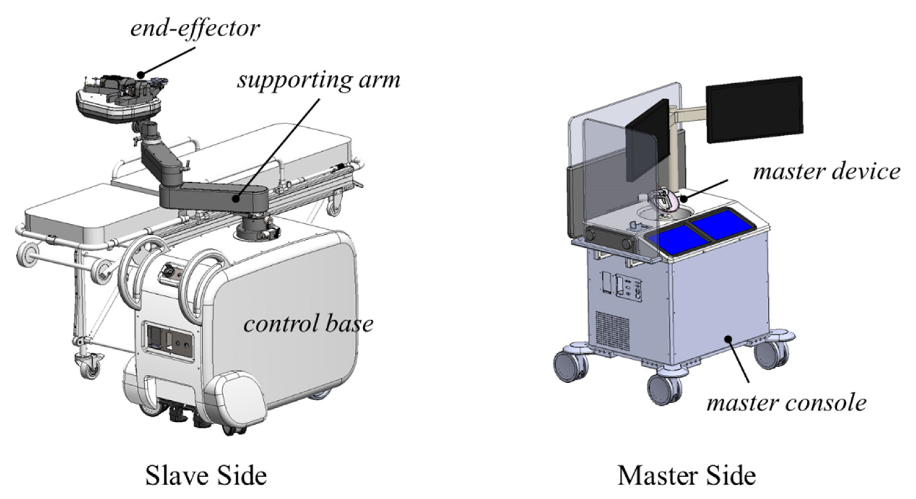
As shown in
Figure 1, our robotic system has a master–slave-type teleoperation configuration that allows the physician to avoid X-ray exposure. The master side is operated by the physician, while the slave side is used for the operation on the patient [
20,
21]. The end-effector of the slave-side system features a set of roller cartridges that can perform both translation and rotation and accommodate instruments with various diameters by an active clamping mechanism in one unified unit for modular configuration.
The translation mechanism advances or retracts vascular instruments by axially rotating the tightly pressed roller pairs. The rotation mechanism rotates vascular instruments by rubbing the roller pair. The roller mechanism was chosen for uninterrupted translational motion control of the vascular instruments [
22,
23,
24].
2.1.2. Design of Slave End-Effector
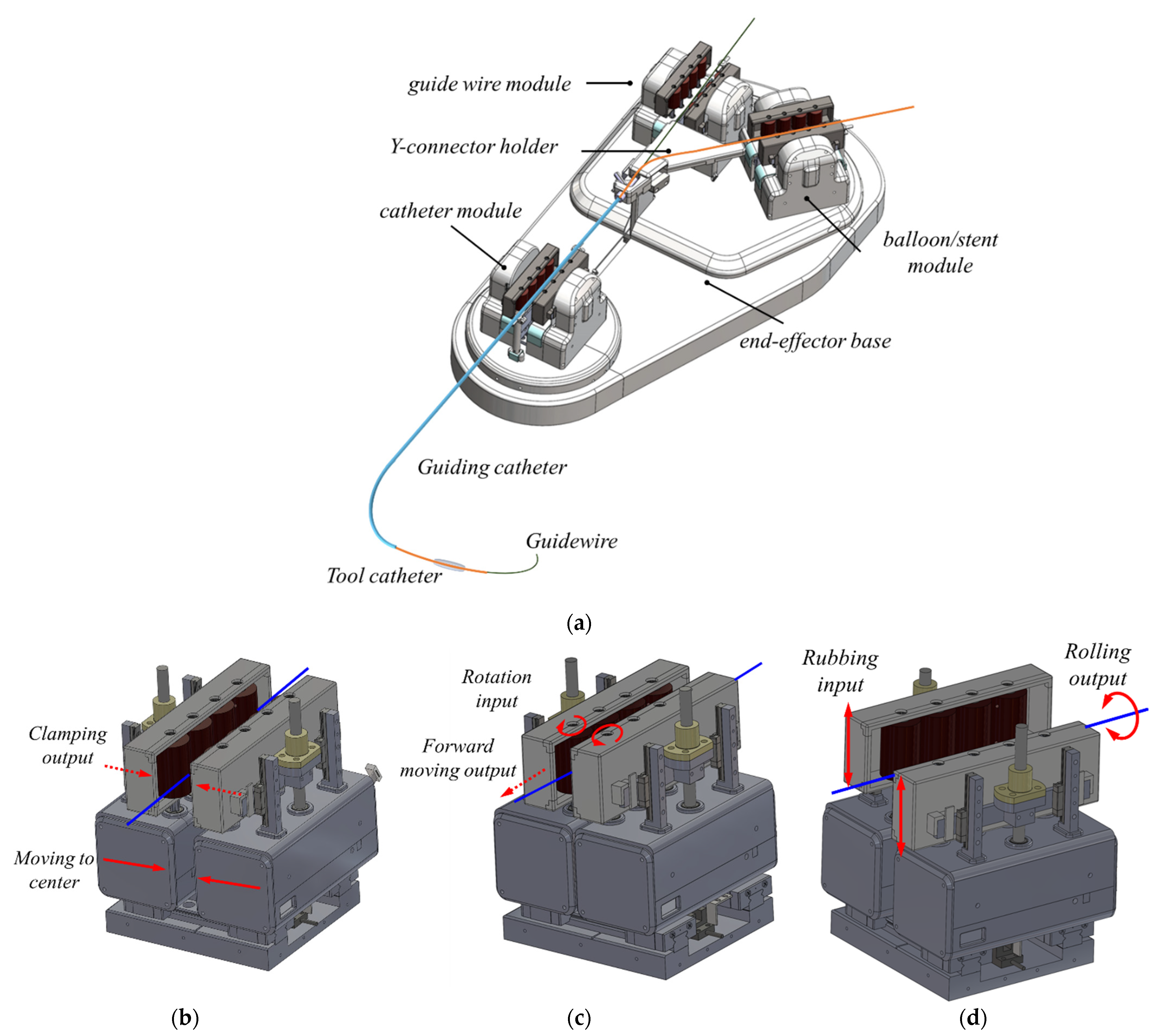
Based on this concept, the end-effector in the slave robot shown in
Figure 2a consists of three modules for three types of instruments, a y-connector supporter, and tool supporters. Three modules are used to separately actuate a guiding catheter, guidewire, and balloon catheter. The guiding catheter and guidewire module are 3-DOF roller systems that clamp, translate, and rotate a target tool shown in
Figure 2b–d. The balloon module is a 2-DOF roller system identical to the other modules, but does not have a rotation function. The guidewire and balloon catheter modules are mounted on a movable base plate in order to maintain the distance to the catheter module, depending on the guiding catheter’s translation.
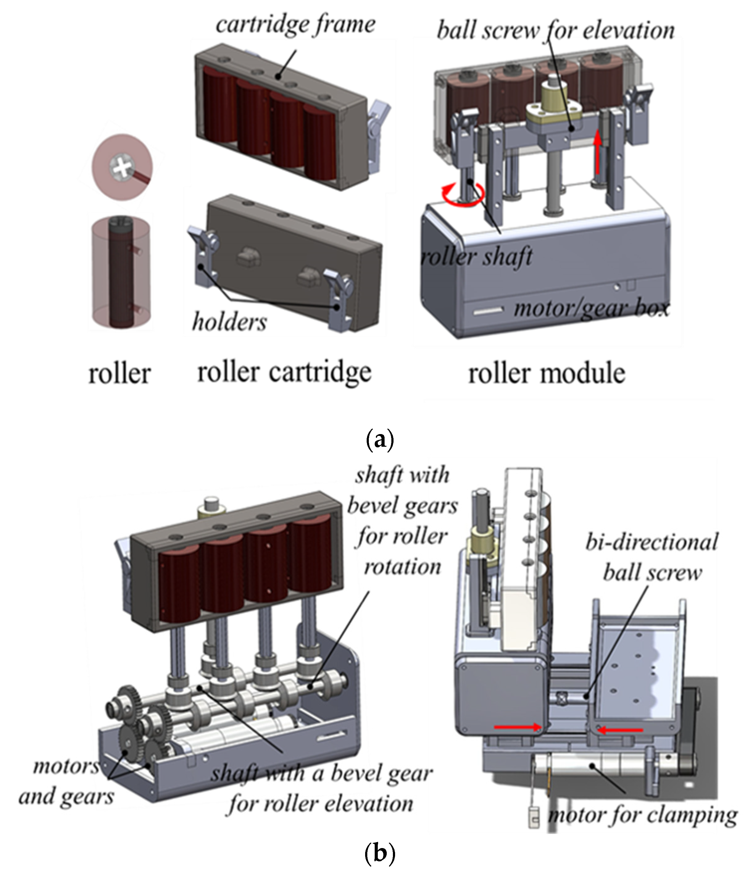
The roller module’s side compartment consists of a motor/gearbox and cartridge frame with four rollers, as shown in
Figure 3. A roller with a 20 mm diameter has a cross-shaped hole for easy insertion into a roller shaft on the motor/gearbox. A roller cartridge contains four rollers and a holder attached to the back of the cartridge frame, allowing it to be quickly assembled and disassembled with the motor/gearbox. The roller cartridge is designed as a disposable part. In the motor/gearbox, there are motors for translation and rotation, and a gear system. Four cross-shaped roller shafts and two linear motion (LM) guide blocks with a horizontal bar are vertically attached to the motor/gear box. The rollers and the holders on the cartridge frames are assembled with the roller shafts and the horizontal bar, respectively. In
Figure 3, a motor is connected to a shaft with bevel gears for roller rotation for the translation mechanism. For the rotation mechanism, a motor is connected to another shaft with a bevel gear for roller elevation, and the cartridge frame assembled with the bar is elevated during rotation. For the clamping mechanism, a clamping motor is connected to a bidirectional ball screw by a timing belt, and the distance between the two compartments attached to each LM guide can be adjusted while clamping.
2.1.3. Design of Master Haptic Device
The master haptic device, which is an improvement of a design presented in a previous study [
25], has been designed as shown in
Figure 4a. A planar mechanism is attached to a moving block under the linear actuator, and the spherical mechanism is attached to the top of the linear actuator. The spherical mechanism captures the wrist rotation movement of the physician holding the grip, which corresponds to the rotational motion of the vascular instrument, as shown in
Figure 4b. The planar mechanism is a widely known 3-RRR-type parallel mechanism [
26,
27,
28]. It consists of a planar orthogonal motion of two DOFs and a vertical axis rotational motion, allowing a 3-DOF movement. While the physician moves the moving platform on the planar mechanism, the forward and backward translational movement is captured and corresponded to the vascular instruments’ translational motion, as shown in
Figure 4c. The linear actuator between the two mechanisms acts as a clutch-like trigger for the movement of the tools. When the physician presses the spherical mechanism downward through the linear actuator, the master–slave teleoperation is connected, and the slave robot motion is locked when released.
2.2. Master–Slave System
2.2.1. Control System
Figure 5 shows the prototype of the master–slave system. Most parts of the prototype, excluding specific metal components and the motors, are manufactured from polyester ether ketone. A master console predominantly consists of a haptic device, two touch panels, a master base, and display monitors. Physicians can select the type, size, and speed of the vascular instruments by pushing buttons on the touch panel. The display monitors also show the real-time fluoroscopy image.
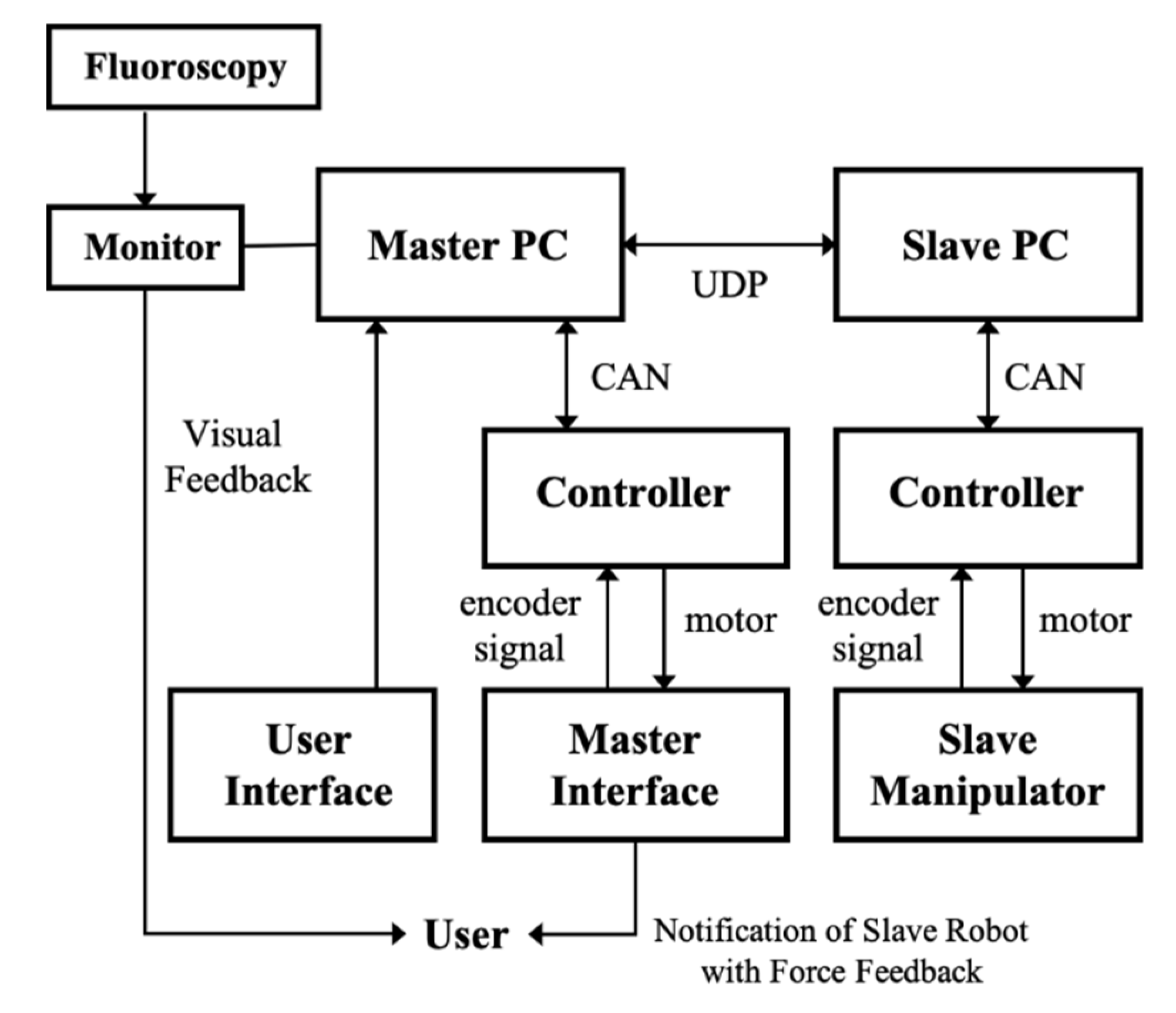
A communication diagram of the master–slave system is shown in
Figure 6. Physicians operate the master device on the master console to control the slave end-effector in order to perform the surgery. At the same time, physicians can monitor the fluoroscopy image through the display monitor in real-time to obtain visual feedback. The master haptic device and slave end-effector are actuated using DC motors (Maxon Motor Inc., Sachseln, Switzerland), which are controlled by PCs and motor drivers in the base of the consoles.
The motor controllers are connected to the PC by a controller area network bus set at 500 Hz. The control software was developed in C++, and the graphic user interface on the touch panels was developed using Qt software (The Qt Company, Santa Clara, CA, USA). The communication frequency of the user datagram between the master and slave control systems is 500 Hz.
2.2.2. Motion Model of Vascular Instruments
According to the roller system’s mechanical structure and dimension, the relationships between the axial displacement and rotation angle of vascular instruments and output angles of the corresponding motors can be calculated.
Translational motion model: the output angle of the translation motor
(rad) and axial displacement of vascular instruments, s (mm), satisfies the following relationship:
where
and
r (mm) denote the ratio of the bevel gears and radius of the roller, respectively.
Rotational motion model: The output angle of the rotation motor and the vertical displacement of the roller modules are
(rad) and
(mm), respectively, which satisfy the following relationship. Then, the rotation angle of the vascular instrument,
(rad), can be obtained by the following:
where
(mm) denotes the radius of the vascular instruments;
and
denote the ratio of bevel gears and ball screw pitch for the elevation of the roller cartridge, respectively.
2.3. Compensation for Rotational Motion
2.3.1. Compensation for the Gap of the Roller Cartridge
As shown in
Figure 7a, the gap in the holder is inevitable because the design has a minimal tolerance for assembling and disassembling the disposable roller cartridge from the bar of the roller system. The gap of the roller cartridge is approximately 1 mm.
Figure 7b shows an example of backlash in the cartridge’s vertical movement, which will be discussed in
Section 4.
Due to this backlash, physicians experience a certain amount of delay in rotational motion when the direction of the motion changes. An experimentally obtained compensation value was used to a resolve the delay.
2.3.2. Haptic Feedback for Rotation Notification
The rotational motion has a limited range due to the limited height of the roller cartridge. The vertical displacement of the roller cartridge during the rotational motion is 25 mm, and the maximum degree of rotation can be between approximately 900° and 1800°, depending on the vascular instrument’s diameter. This appears to be sufficient to rotate the vascular instruments required during surgery.
For the physician to recognize the rotational motion limit, haptic feedback of the repulsing force is rendered on the master grip when the roller cartridge in the slave end-effector approaches the limit. The haptic feedback is implemented as follows. First, the range of cartridges is set for haptic feedback. As shown in
Figure 8a, the difference in height between the two cartridges is set as
(mm). Then, the movement is performed with the motor’s current control in the spinal mechanical part of the spherical mechanism of the master haptic device, and the force and direction provided to the physician are determined. The inverse kinematics problem of the spherical mechanism is solved to determine the angular displacements of each motor on the mechanism for the given coordinate of
E.
,
,
,
and
intersect at a common point O.
is in the x–z plane and
is in the y–z plane. Therefore, two angles are defined as
and
, as shown in
Figure 8c. For the position of the
set as
in
Figure 8b, the vector of the grip is determined as follows:
Next, we determine the amount of force for the haptic feedback according to the roller cartridge range. The current exerted at the position of the roller cartridge,
, is calculated according to (4). The current drawn is directly proportional to the torque developed by the motor.
where
is the current for the rotation motor on the right of the grip of the master haptic device and
is the current for the rotation motor on the left. The slope and
y-intercept of the linear function are calculated by (5). The value of each parameter is as follows:
where
and
indicate the angles at the current status, and
and
indicate the angles at the previous status.
3. Performance Evaluation and Results
Experiments were conducted to evaluate the accuracy and precision of the vascular instruments’ motion when operating the system, and to assess the robot-assisted intervention’s effectiveness.
3.1. Compensation Method Evaluation
3.1.1. The Gap in the Roller Cartridge
A laser sensor (HL-G103-S-J, Panasonic, Kadoma City, Japan) was placed vertically on the cartridge, and the vertical displacement of the roller cartridge was measured. An incremental command allows it to move up or down at regular intervals of 0.06 mm, which is the amount required for a 10° rotation of the guidewire. One trial included five increments of descending, ascending, and descending, and a total of 20 trials were performed. The displacement loss value was obtained through the 20 initial experiments without a compensation control. Then, the trials with a compensation control were repeated, changing the rotational direction.
As a result,
Figure 9a shows that the proposed compensation method improved the backlash in the roller cartridge’s vertical motion. The accuracy of the system was quantified by measuring the theoretical displacements and the averaged displacements with/without compensation in every trial, and calculating the root mean square error (RMSE). The RMSEs of the displacement with/without the compensation method were 0.0022 mm and 0.0055 mm, respectively. The system was able to follow the desired displacement accurately, reducing the RMSE by 40%.
3.1.2. Haptic Feedback for Rotation Notification
When an physician first rotates the grip of the master haptic device in the clockwise direction, from the initial position for feedback (), −6.325 mm, to the maximum direction (), −6.5 mm, of the roller cartridge, we checked whether the torque value of the motor depends on , , and the position of the roller cartridge, in (3) to (6). The two DC motors of the grip have a maximum power of 24 W and maximum continuous torque of 15.3 mNm. Moreover, the torque constant () is 18.4 mNm/A. When the physician rotated the grip in the opposite direction, from the initial position for feedback () of 6.325 mm to the maximum direction () of 6.5 mm of the roller cartridge, the torques were checked.
As a result,
Figure 10 illustrates the torques for haptic feedback, depending on the directions of
and
, and the position of the roller cartridge. When the displacement of the roller cartridge reached from
to
, the torque of the left motor for
increased linearly and that of the right motor decreased linearly, and the torques of the left and right motors were 15.364 and –15.364 mNm, respectively, at −6.5 mm, for the clockwise rotation. Conversely, the torques of the left and right motors were −15.364 and 15.364 mNm, respectively, at –6.5 mm for the clockwise rotation.
3.2. Accuracy Test of the Motion of Vascular Instruments
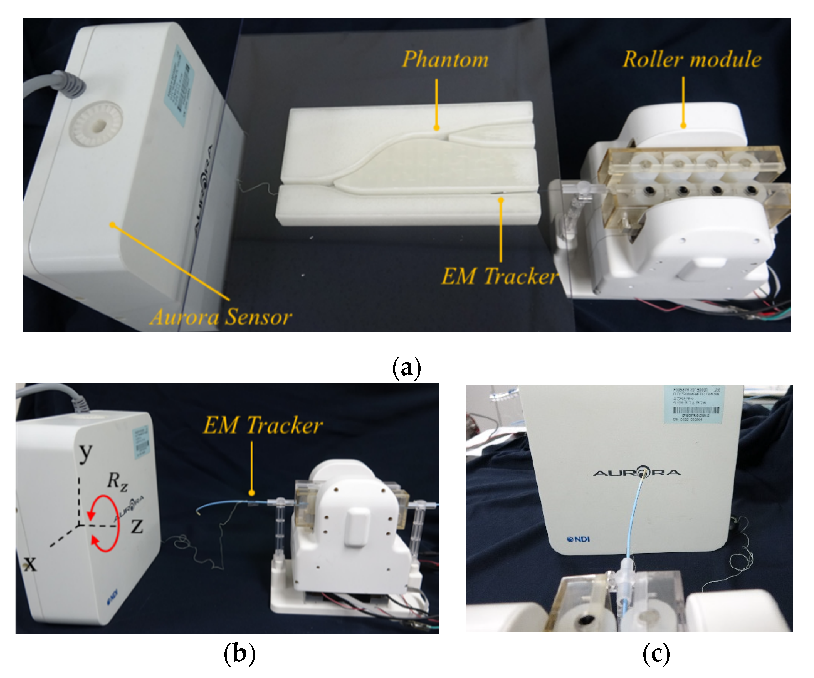
We conducted a series of experiments to characterize the accuracy and precision of the modularized system with an active clamping mechanism in the axial and radial directions. The experiment was set up as shown in
Figure 11. The vascular instruments used in the experiment were a 5-F catheter, 0.014-inch guidewire, and a balloon catheter (3.5 × 15 mm). The actual displacement and angle of the vascular instruments were measured by using an electromagnetic (EM) tracking sensor with six DOFs (Aurora system, Northern Digital Inc., Waterloo, ON, Canada). The accuracy was evaluated in terms of the absolute error (between the actual displacement/angle of the vascular instruments and the theoretical displacement). The axial and radial precision was evaluated by calculating the standard deviation of the absolute error.
The accuracy and precision in translation were evaluated while the vascular instruments were placed in a 5 mm diameter vascular 2D path model produced by 3D printing, which was used to avoid introducing measurement error owing to the elastic deformation of the vascular instruments. To evaluate the accuracy and precision, the vascular instruments were advanced from 0 to 10, 20, 30, 40, and 50 mm, ten times in succession. An EM sensor was attached at the distal end of the vascular instruments and the spatial coordinates could be provided by the EM tracking system. The actual displacement of the catheter can be calculated by the following:
where (
) is the coordinate of the start point, and (
) is the coordinate of the end point.
To evaluate the accuracy and precision of rotational motion, the guiding catheter and guidewire were rotated by the roller module, from 0° to 360°, ten times, and the actual angles were measured. An EM sensor was attached at the position where it begins to flatten from the tip of the vascular instruments. The constant command was sent to the rotation motor repeatedly, to rotate the guiding catheter and guidewire 10 times. The accuracy of the EM tracking system is 0.48 mm RMS per the specification.
As a result, the accuracy and precision of vascular instruments in translation are listed in
Table 1, and their accuracy and precision in rotation are listed in
Table 2.
3.3. Evaluation of the Master–Slave Robotic System
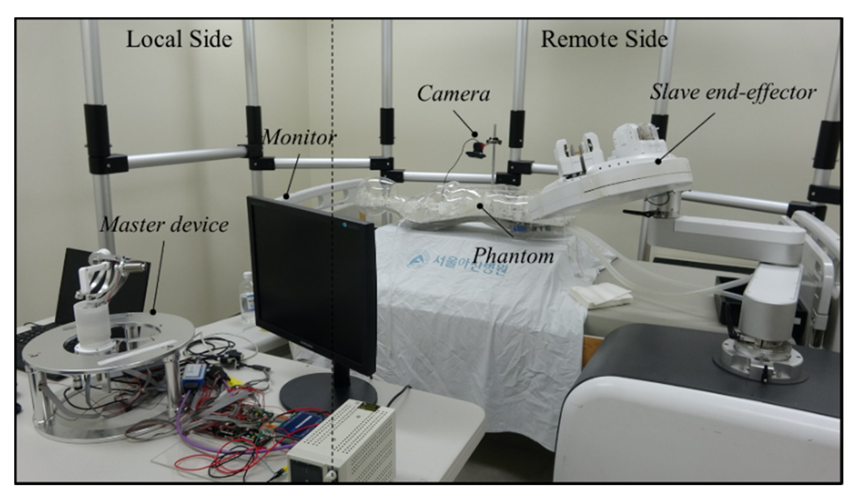
To test the transmission accuracy of a guidewire and balloon catheter, the experiment was conducted on a silicon cardiovascular model. The experimental setup, as shown in
Figure 12, consisted of two parts. In the remote site, a silicone-based vascular phantom (EndoVascular Evaluator (EVE), FAIN-Biomedical Inc., Japan) was used. The slave end-effector actuated the guidewire and balloon catheter into the EVE model. A camera was mounted immediately beside the EVE model, in order to obtain visual feedback during the experimental process. In the local site, the physician navigated the vascular instruments through the master haptic device to guide the vascular instruments from the femoral artery to several targets in the EVE model. The 5-F guiding catheter placement was performed manually through the brachial artery for arterial access. A 2.5 mm × 15 mm balloon catheter and a 0.014-inch guidewire were loaded into the roller module separately. The image information from the camera was presented on the computer monitor. The guidewire and balloon catheter were controlled by the master–slave robotic system to enter different vascular branches.
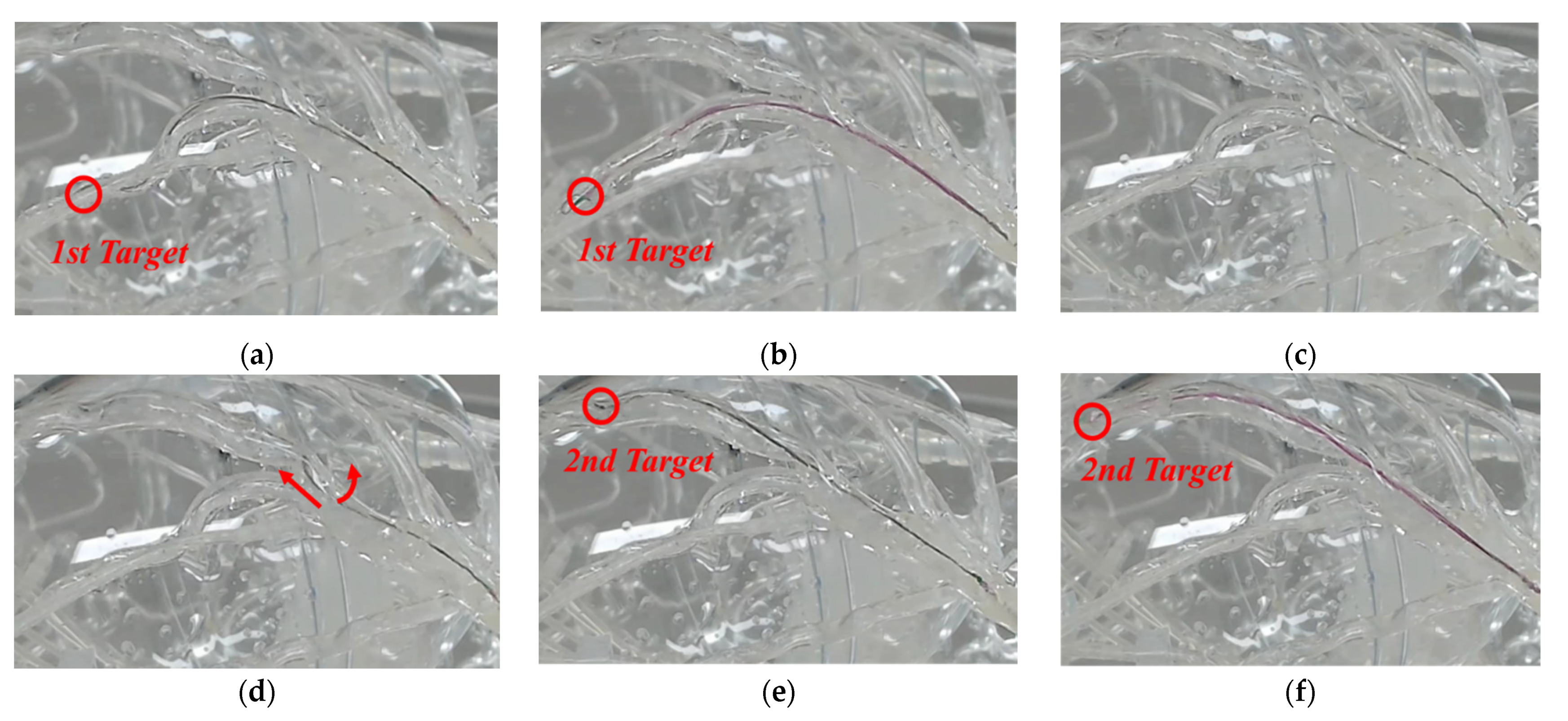
Figure 13 shows that the guidewire and balloon catheter were located in the two targets.
Figure 13a shows that the guidewire was advanced and positioned at the first target, and
Figure 13b illustrates that the balloon catheter was advanced through the guidewire to the target point, and positioned fully at the first target. As shown in
Figure 13c,d, the physician worked on the master device to operate the slave end-effector, to achieve simultaneous translational and rotational motions of the guidewire, and the guidewire was advanced to a new branch quickly and accurately. In
Figure 13e,f, it can be observed that the guidewire advanced and reached the second target. Then, the balloon catheter was also advanced through the guidewire and positioned at the second target. The experiment confirmed that the guidewire and balloon catheter can be smoothly moved and precisely positioned using the proposed system.
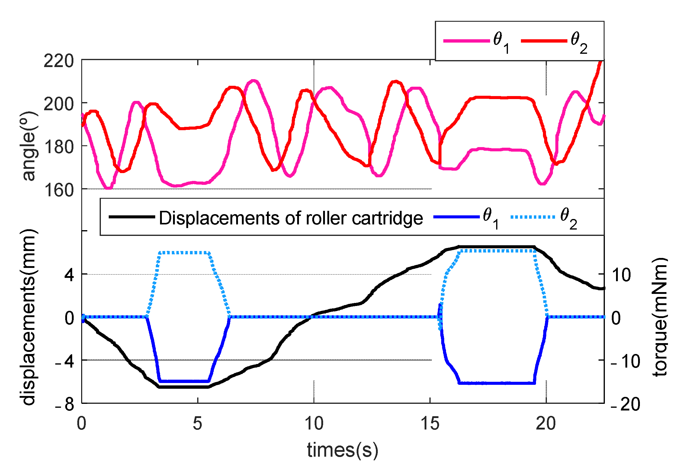
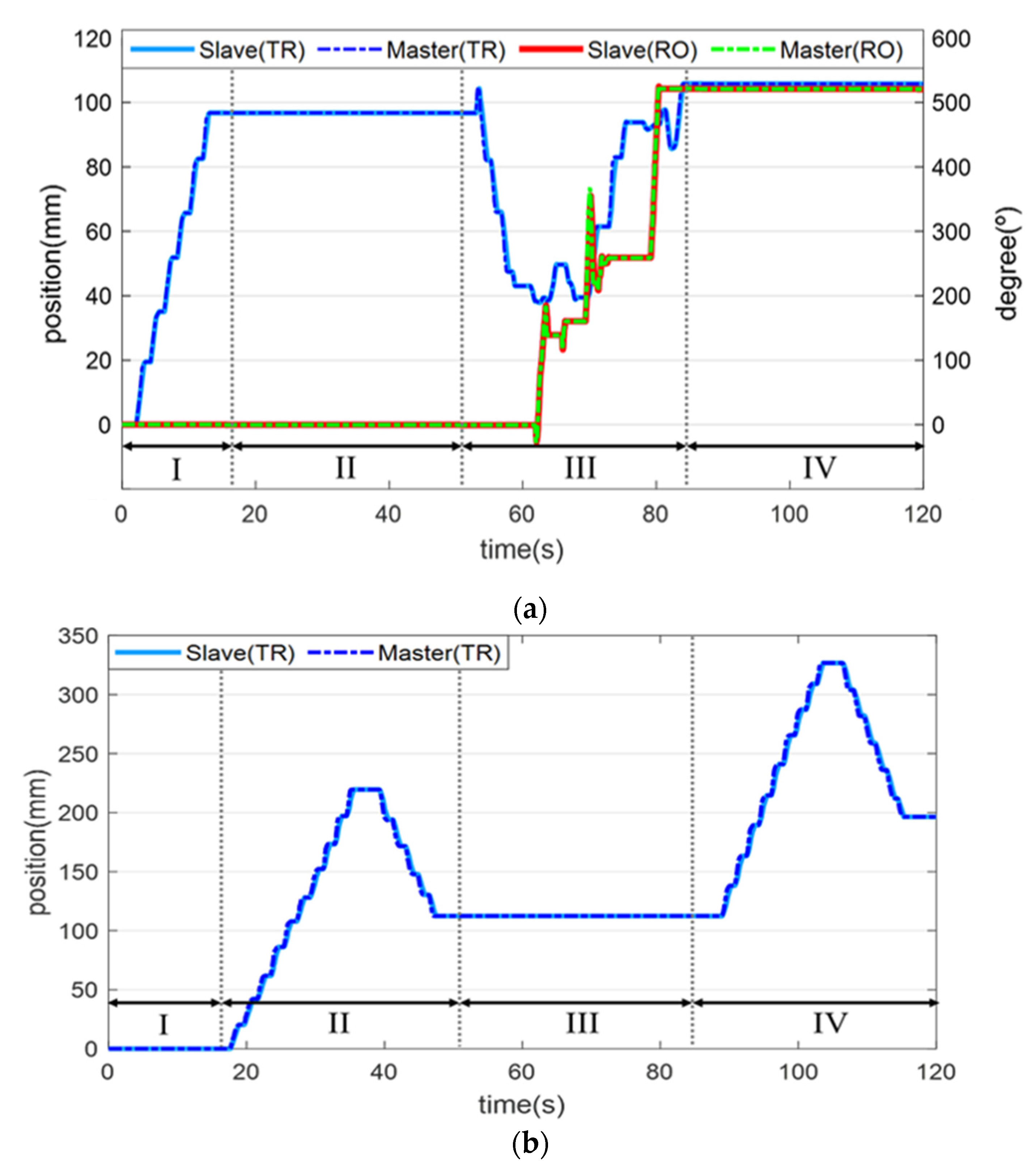
Figure 14 illustrates the translational and rotational motion trajectories of the guidewire and balloon catheter in the master and slave systems in the phantom experiment. In stage 1, the guidewire was inserted into the first target for translational motion, and in stage 2, the balloon catheter was inserted into the first target. Then, in stage 3, the guidewire was simultaneously advanced and rotated to move to the other branch, and it reached the second target. In stage 4, the balloon catheter was inserted into the second target.
3.4. Animal Experiment
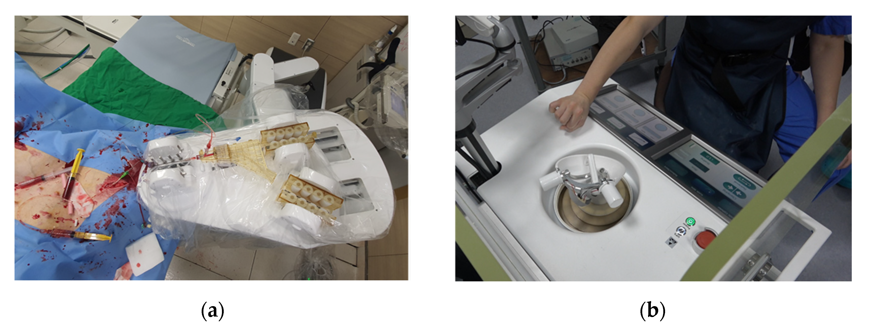
An animal experiment, using a porcine model, was performed to verify the proposed system’s functionality and safety under an IACUC (Institutional Animal Care and Use Committee) approval of the Osong Medical Innovation Foundation, Republic of Korea (KBIO-IACUC-2019-105-1), as shown in
Figure 15. The guiding catheter was manually inserted and engaged in the coronary ostium in a 60 kg female pig. The physician operated the master console to remotely control the slave end-effector for the translation and rotation of the guidewire under angiography image guidance. The robotic system inserted a guidewire from the entrance of the coronary artery to the targets in the right coronary artery.
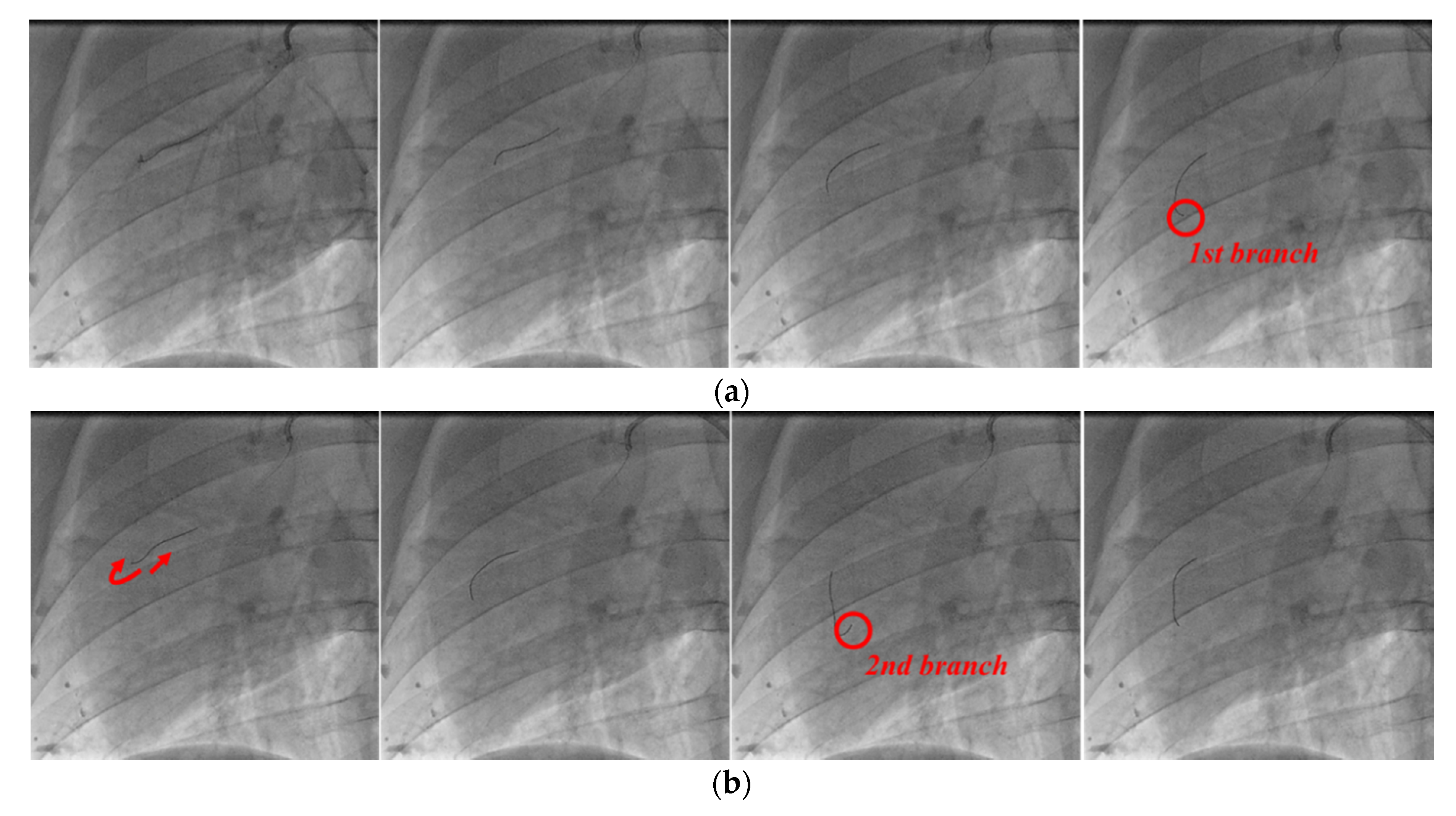
The angiography images of each stage in the process of guidewire advancement are shown in
Figure 16. The guidewire was advanced, and it reached the first branch point, as shown in
Figure 16a. Then, the guidewire was withdrawn from the first branch by moving it backward and rotating it, and it was advanced again to reach the second branch, as shown in
Figure 16b. Finally, the guidewire was retracted and rotated again to exit from the second branch point, and then it was advanced to successfully reach the final target location, as shown in
Figure 16c. In postoperative observation, the physician confirmed that there were no complications, such as perforation or bleeding.
3.5. Clinical Trial
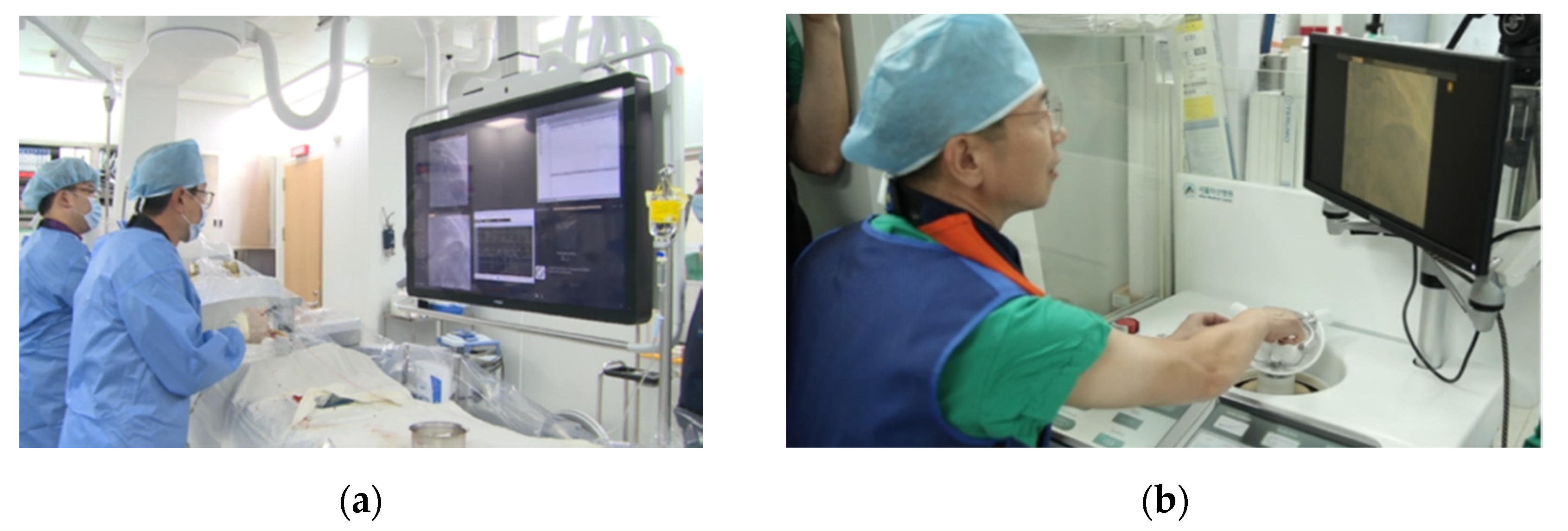
A single-center, single-group clinical trial was conducted on two patients requiring coronary angiography at Asan Medical Center, Seoul, Republic of Korea (Asan Medical Center Institutional Review Board Registration Number: S2018-2377-0002, Korean Ministry of Drug and Food Safety approval: 20190064902), as shown in
Figure 17. The clinical trial procedure was conducted as follows:
Setup of robot was prepared, such as sterile drapes and loading detachable sterilized rollers.
Arterial access and guiding catheter placement of coronary ostium were performed manually.
After the guiding catheter was completely located in the coronary artery, using the manual robot arm in the slave robot, the slave end-effector was positioned beside the bed on which the patient was lying, and the master console was located far from the patient. A guidewire was loaded by a tableside assistant into appropriate roller modules, which served as the sterile interface between the slave end-effector and the patient.
The physician sat in front of the master console, behind a radiation-shielded wall, and used the master haptic device and touchscreen controls to advance, retract, rotate, and deploy the devices as required.
A guidewire was inserted into the target vessel site using a robotic system, through a guiding catheter inserted manually.
When the guidewire was positioned at the desired location, coronary angiography was completed.
After 4 h of bed stability, patients were monitored for bleeding complications, and at 24 h after the procedure, patients were checked for the occurrence of an abnormal event/severe abnormal event.
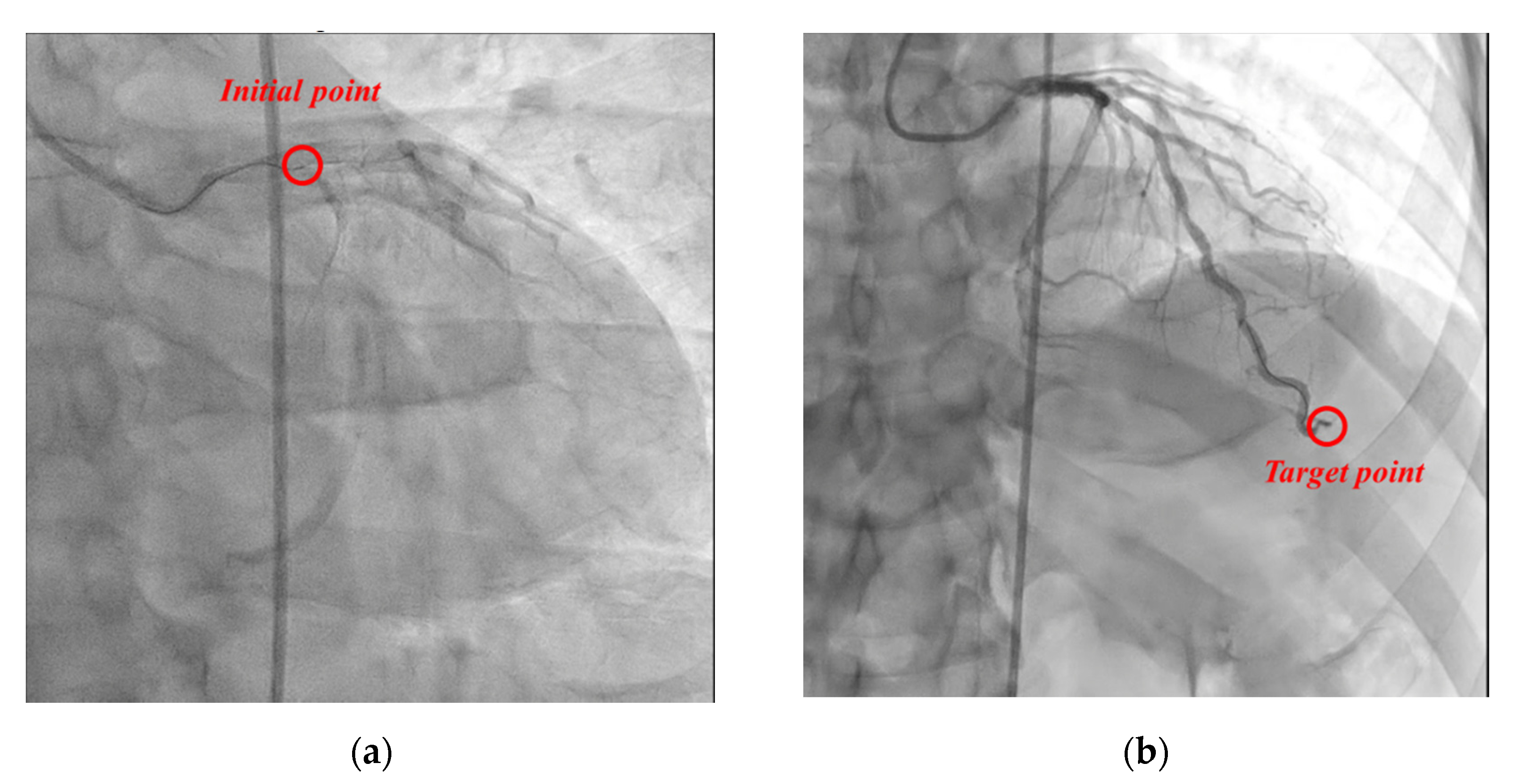
For efficacy evaluation, in the coronary angiography of the two subjects participating in this clinical trial, the guidewire was transferred to the target site of the coronary artery (subject 1: “left anterior descending artery”, subject 2: “right coronary artery”) using the proposed master–slave robotic system, without manual manipulation, as shown in
Figure 18. At this time, there was no damage or dissection of the distal intima (“Coronary artery dissection—The National Heart, Lung and Blood Institute classification” criteria, evaluated as type A). Accordingly, coronary angiography using the proposed master–slave robotic system of the two subjects registered in this clinical trial was evaluated as a “technological success”.
4. Discussion
A master–slave robotic system with roller cartridge-based modules for robotic cardiovascular intervention has been developed for clinical application. Preliminary experiments were conducted to evaluate the performance of the roller cartridge-based modularized robotic system. Specific problems associated with the roller cartridges were adequately alleviated by compensation control and a force rendering method using the master haptic device. Through the experiment using the phantom, we checked the functionality and safety of the master–slave robotic system. It was confirmed that no significant problems were identified in the master–slave system, and the positioning precision and accuracy of the guidewire and balloon catheter were also sufficiently high. It was also shown that the combination of translation, rotation, and their simultaneous motion enables vascular instruments to navigate to the desired location in the vascular branches. The in vivo animal experiment confirmed that navigating a guidewire in several branches worked smoothly as the physician manipulated the master haptic device. In the clinical trial, the initial verification and validity of the prototype of the master–slave robotic system was confirmed by navigating the guidewire to the target location completely. Further in vivo tests should be performed to assess the clinical efficacy of the system.
Maor et al. presented the limitations of an existing percutaneous coronary intervention (PCI) robot, such as the absence of tactile feedback and limited applicability to various complex vascular intervention procedures [
29]. The system presented in this paper is similar to the Corpath system in its purpose and instrumentation motion. Although a haptic device has been implemented in the master console, the utilization was only for a virtual wall in the rotation operation. Further development and evaluation are needed and are underway to appropriately show the usefulness of the haptic device that is designed to capture and interact with the physician’s positional and rotational motion via the 6-DOF mechanism. The haptic device’s prominent role seems to be more for the haptic rendering to augment the virtual structure and sensation to facilitate the physician’s situation awareness and instrumentation maneuver than repulsive force feedback, which is limited by various attenuation factors in PCI procedures. Some physicians who tested the system in the usability viewpoint commented that PVI (peripheral vascular intervention) procedures might better utilize the force feedback.
The force feedback can be helpful in the manipulation of guidewires in PCI or PVI procedures. However, guidewires have soft and flexible ends for safer maneuver in the blood vessel. The repulsive force is largely attenuated due to the tip property and various frictions over the vessel path. In the cardiac ablation procedures, the contact force of the ablation catheter is essential and can be sensed by various methods, such as direct measurement using sensor structures embedded in the catheter, or indirect estimation using image analysis of the catheter body shape deformation in fluoroscopy. It is difficult to sense or estimate the repulsive force over the whole range in the case of the guidewire in the PCI procedure. Although relatively large repulsion, such as hitting the obstruction or friction during passing through an abrupt curve in the vessel, can be sensed at the proximal part of the instrument, physicians’ experience and opinions vary. The methods for the repulsive force measurement and direct force feedback need further study, and this is under experiment by many researchers, including the authors.
Unlike marvelous human finger motion, artificial mechanical systems should be passive locking mechanisms with fixed grabbing forces, or active motorized mechanisms with more complex and bulky structures. As the complexity of the PCI procedure increases, various instruments, with different diameters, internal structures, and stiffness of the enclosing material, are engaged. The active clamping mechanism in our system is to facilitate those complex PCI procedures better. The integrated cassette configuration of the Corpath systems’ disposable part, enclosing all parts in one closed housing, has the advantage of relatively easy and fast installation, among other features. In comparison, our system modularized and separated all the disposable parts without closed housing. As a result, the volume and surface area of the sterile parts are relatively smaller, and the reduced complexity in the structure favors reliability. In an emergency, manual conversion can be more easily and quickly performed by simply lifting the instruments minimizing unwanted motion inside the patient, since there is no enclosing structure.
There is a need for a method to solve various nonlinear factors caused by interactions between surgical environmental factors, instruments, and robots. Machine learning-based control methods, such as reinforcement learning, could be a plausible approach. In addition, a new slave end-effector mechanism for complex PCI and control methods, to ensure autonomy in robotic procedures and perform safer tasks in less time, is under development.
5. Conclusions
In this study, a novel master–slave robotic system was developed. Pre-clinical in vitro and in vivo tests showed that the slave end-effector could control the translational and rotational motions of the vascular instruments with satisfactory performance. The clinical trial proved the essential safety and performance of the system to effectively assist the physician in vascular interventions.
Author Contributions
Conceptualization, J.C. (Jaesoon Choi); methodology, J.C. (Jueun Choi) and Y.M.; software, J.C. (Jueun Choi) and S.P.; validation, J.C. (Jueun Choi) and Y.M.; investigation, J.C. (Jueun Choi); re-sources, Y.-H.K.; writing—original draft preparation, J.C. (Jueun Choi) and Y.M.; writing—review and editing, J.C. (Jueun Choi) and Y.M.; supervision, J.C. (Jaesoon Choi); project administration, J.C. (Jaesoon Choi). All authors have read and agreed to the published version of the manuscript.
Funding
This research was supported by the Ministry of Trade Industry & Energy (MOTIE, Korea), Minis-try of Science & ICT (MSIT, Korea), and Ministry of Health & Welfare (MOHW, Korea) under Technology Development Program for AI-Bio-Robot-Medicine Convergence (grant number: 20001638), by a grant of the Korea Health Technology R&D Project through the Korea Health In-dustry Development Institute (KHIDI), funded by the Ministry of Health & Welfare, Republic of Korea (grant number: HI17C2410), and by a grant of the Asan Institute for Life Sciences intra-mural research project funded by Asan Medical Center (grant number: 2019IP0647, 2017IL0647).
Institutional Review Board Statement
The animal study was approved by the Institutional Animal Care and Use Committee of the Osong Medical Innovation Foundation (approval number: KBIO-IACUC-2019-105-1). The clinical study was approved by Korean Ministry of Drug and Food Safety (approval number: 20190064902) and conducted according to the guidelines of the Declaration of Helsinki and approved by Asan Medical Center Institutional Review Board (registration number: S2018-2377-0002, protocol number: AMCCD-01).
Informed Consent Statement
Informed consent was obtained from all subjects involved in the study.
Data Availability Statement
Not applicable.
Conflicts of Interest
The authors declare no conflict of interest.
References
- Mohapatra, A.; Greenberg, R.K.; Mastracci, T.M.; Eagleton, M.J.; Thornsberry, B. Radiation exposure to operating room personnel and patients during endovascular procedures. J. Vasc. Surg. 2013, 58, 702–709. [Google Scholar] [CrossRef] [Green Version]
- Klein, L.W.; Miller, D.L.; Balter, S.; Laskey, W.; Naito, N.; Haines, D.; Ross, A.; Mauro, M.A.; Goldstein, J.A. Occupational health hazards in the interventional laboratory: Time for a safer environment. Catheter Cardiovasc. Interv. 2018. [Google Scholar] [CrossRef]
- Rafii-Tari, H.; Payne, C.J.; Yang, G.Z. Current and emerging robot-assisted endovascular catheterization technologies: A review. Ann. Biomed. Eng. 2014, 42, 697–715. [Google Scholar] [CrossRef] [PubMed]
- Costa, M.A.; Angiolillo, D.J.; Tannenbaum, M.; Driesman, M.; Chu, A.; Patterson, J.; Kuehl, W.; Battaglia, J.; Dabbons, S.; Shamoon, F.; et al. STLLR Investigators. Impact of stent deployment procedural factors on long-term effectiveness and safety of sirolimus-eluting stents (final results of the multicenter prospective STLLR trial). Am. J. Cardiol. 2008, 101, 1704–1711. [Google Scholar] [CrossRef]
- Carrozza, J.P., Jr. Robotic-assisted percutaneous coronary intervention-filling an unmet need. J. Cardiovasc. Transl. Res. 2012, 5, 62–66. [Google Scholar] [CrossRef]
- Mahmud, E.; Dominguez, A.; Bahadorani, J. First-in-human robotic percutaneous coronary intervention for unprotected left main stenosis. Catheter Cardiovasc. Interv. 2016, 88, 565–570. [Google Scholar] [CrossRef]
- Omisore, O.M.; Han, S.P.; Ren, L.X.; Wang, G.S.; Ou, F.L.; Li, H.; Wang, L. Towards Characterization and Adaptive Compensation of Backlash in a Novel Robotic Catheter System for Cardiovascular Interventions. IEEE Trans. Biomed. Circuits Syst. 2018, 12, 824–838. [Google Scholar] [CrossRef] [PubMed]
- Mahmud, E.; Pourdjabbar, A.; Ang, L.; Behnamfar, O.; Patel, M.P.; Reeves, R.R. Robotic technology in interventional cardiology: Current status and future perspectives. Catheter Cardiovasc. Interv. 2017, 90, 956–962. [Google Scholar] [CrossRef]
- Riga, C.V.; Bicknell, C.D.; Rolls, A.; Cheshire, N.J.; Hamady, M.S. Robot-assisted fenestrated endovascular aneurysm repair (FEVAR) using the Magellan system. J. Vasc. Interv. Radiol. 2013, 24, 191–196. [Google Scholar] [CrossRef]
- Rolls, A.E.; Riga, C.V.; Bicknell, C.D.; Regan, L.; Cheshire, N.J.; Hamady, M.S. Robot-assisted uterine artery embolization: A first-in-woman safety evaluation of the Magellan System. J. Vasc. Interv. Radiol. 2014, 25, 1841–1848. [Google Scholar] [CrossRef]
- Riga, C.; Bicknell, C.; Hamady, M.S.; Cheshire, N.J. Robotically-steerable catheters and their role in the visceral aortic segment. J. Cardiovasc. Surg. 2011, 52, 353–362. [Google Scholar]
- Weisz, G.; Metzger, D.C.; Caputo, R.P.; Delgado, J.A.; Marshall, J.J.; Vetrovec, G.W.; Reisman, M.; Waksman, R.; Granada, J.F.; Novack, V.; et al. Safety and feasibility of robotic percutaneous coronary intervention: PRECISE (Percutaneous Robotically-Enhanced Coronary Intervention) Study. J. Am. Coll. Cardiol. 2013, 61, 1596–1600. [Google Scholar] [CrossRef] [PubMed] [Green Version]
- Hooshiar, A.; Najarian, S.; Dargahi, J. Haptic Telerobotic Cardiovascular Intervention: A Review of Approaches, Methods, and Future Perspectives. IEEE Rev. Biomed. Eng. 2020, 13, 32–50. [Google Scholar] [CrossRef]
- Thakur, Y.; Bax, J.S.; Holdsworth, D.W.; Drangova, M. Design and performance evaluation of a remote catheter navigation system. IEEE Trans. Biomed. Eng. 2009, 56, 1901–1908. [Google Scholar] [CrossRef] [PubMed]
- Thakur, Y.; Holdsworth, D.W.; Drangova, M. Characterization of catheter dynamics during percutaneous transluminal catheter procedures. IEEE Trans. Biomed. Eng. 2009, 56, 2140–2143. [Google Scholar] [CrossRef] [PubMed]
- Tavallaei, M.A.; Lavdas, M.K.; Gelman, D.; Drangova, M. Magnetic resonance imaging compatible remote catheter navigation system with 3 degrees of freedom. Int, J. Comput. Assist. Radiol. Surg. 2016, 11, 1537–1545. [Google Scholar] [CrossRef] [PubMed]
- Cha, H.J.; Yi, B.J.; Won, J.Y. An assembly-type master-slave catheter and guidewire driving system for vascular intervention. Proc. Inst. Mech Eng. H 2017, 231, 69–79. [Google Scholar] [CrossRef]
- Zhou, X.H.; Bian, G.B.; Xie, X.L.; Hou, Z.G. An Interventionalist-Behavior-Based Data Fusion Framework for Guidewire Tracking in Percutaneous Coronary Intervention. IEEE Trans. Syst. Man Cybern. Syst. 2020, 50, 4836–4849. [Google Scholar] [CrossRef]
- Zhou, X.H.; Bian, G.B.; Xie, X.L.; Hou, Z.G.; Qu, X.; Guan, S. Analysis of Interventionalists’ Natural Behaviors for Recognizing Motion Patterns of Endovascular Tools During Percutaneous Coronary Interventions. IEEE Trans. Biomed. Circuits Syst. 2019, 13, 330–342. [Google Scholar] [CrossRef]
- Mangels, D.R.; Giri, J.; Hirshfeld, J.; Wilensky, R.L. Robotic-assisted percutaneous coronary intervention. Catheter Cardiovasc. Interv. 2017, 90, 948–955. [Google Scholar] [CrossRef]
- Walters, D.; Omran, J.; Patel, M.; Reeves, R.; Ang, L.; Mahmud, E. Robotic-Assisted Percutaneous Coronary Intervention: Concept, Data, and Clinical Application. Interv. Cardiol. Clin. 2019, 8, 149–159. [Google Scholar] [CrossRef]
- Feng, Z.-Q.; Bian, G.-B.; Xie, X.-L.; Hou, Z.-G.; Hao, J.-L. Design and evaluation of a bio-inspired robotic hand for percutaneous coronary intervention. In Proceedings of the 2015 IEEE International Conference on Robotics and Automation (ICRA), Seattle, WA, USA, 26–30 May 2015; pp. 5338–5343. [Google Scholar] [CrossRef]
- Srimathveeravalli, G.; Kesavadas, T.; Li, X. Design and fabrication of a robotic mechanism for remote steering and positioning of interventional devices. Int. J. Med. Robot. 2010, 6, 160–170. [Google Scholar] [CrossRef] [PubMed]
- Meng, C.; Guan, S.; Sun, S.; Liu, Y.; Wang, T. A novel catheter operating robot for vascular interventional surgery. In Proceedings of the 2016 IEEE Workshop on Advanced Robotics and its Social Impacts (ARSO), Shanghai, China, 8–10 July 2016; pp. 304–309. [Google Scholar] [CrossRef]
- Moon, Y.; Hu, Z.; Won, J.; Park, S.; Lee, H.; You, H.; Nam, G.B.; Choi, J. Novel Design of Master Manipulator for Robotic Catheter System. Int. J. Control. Autom. Syst. 2018, 16, 2924–2934. [Google Scholar] [CrossRef]
- Merlet, J.P. Direct kinematics of planar parallel manipulators. In Proceedings of the IEEE International Conference on Robotics and Automation, Minne, MN, USA, 22–28 April 1996. [Google Scholar] [CrossRef]
- Gosselin, C.; Angeles, J. The Optimum Kinematic Design of a Planar Three-Degree-of-Freedom Parallel Manipulator. ASME J. Mech. Trans. Autom. 1988, 110, 35–41. [Google Scholar] [CrossRef]
- Arakelian, V.H.; Smith, M.R. Design of planar 3-DOF 3-RRR reactionless parallel manipulators. Mechatronics 2008, 18, 601–606. [Google Scholar] [CrossRef]
- Maor, E.; Eleid, M.F.; Gulati, R.; Lerman, A.; Sandhu, G.S. Current and Future Use of Robotic Devices to Perform Percutaneous Coronary Interventions: A Review. J. Am. Heart Assoc. 2017, 6, e006239. [Google Scholar] [CrossRef] [PubMed]
Figure 1.
Overall configuration of the system.
Figure 1.
Overall configuration of the system.
Figure 2.
(a) The slave end-effector and the motion principles of (b) clamping mechanism, (c) translation mechanism, and (d) rotation mechanism in the roller module.
Figure 2.
(a) The slave end-effector and the motion principles of (b) clamping mechanism, (c) translation mechanism, and (d) rotation mechanism in the roller module.
Figure 3.
(a) Design of roller, roller cartridge, and side compartment of roller module. (b) Design of motor/gear box and clamping device of roller cartridge.
Figure 3.
(a) Design of roller, roller cartridge, and side compartment of roller module. (b) Design of motor/gear box and clamping device of roller cartridge.
Figure 4.
Design of (a) the master haptic device and master haptic device matching concept, (b) rotational motion, (c) translation motion.
Figure 4.
Design of (a) the master haptic device and master haptic device matching concept, (b) rotational motion, (c) translation motion.
Figure 5.
Clinical prototype of the robot system.
Figure 5.
Clinical prototype of the robot system.
Figure 6.
Communication diagram of the master–slave system.
Figure 6.
Communication diagram of the master–slave system.
Figure 7.
Characteristics of the roller cartridge. (a) Gap between the roller cartridge and the bar of the roller module. (b) Position of the roller cartridge by pre-compensated control.
Figure 7.
Characteristics of the roller cartridge. (a) Gap between the roller cartridge and the bar of the roller module. (b) Position of the roller cartridge by pre-compensated control.
Figure 8.
Concept of rotation notification. (a) Roller cassettes depending on rotational direction. (b) Top view (projection on x–y plane) of the master grip. (c) Isometric view.
Figure 8.
Concept of rotation notification. (a) Roller cassettes depending on rotational direction. (b) Top view (projection on x–y plane) of the master grip. (c) Isometric view.
Figure 9.
Result of the compensation experiment of the gap of the roller cartridge. (a) Position of the roller cartridge from the laser sensor with/without compensation. (b) Without compensation. (c) With compensation; the data include the median and range of measured errors for 20 trials.
Figure 9.
Result of the compensation experiment of the gap of the roller cartridge. (a) Position of the roller cartridge from the laser sensor with/without compensation. (b) Without compensation. (c) With compensation; the data include the median and range of measured errors for 20 trials.
Figure 10.
Torques for the haptic feedback depending on the directions of , , and the position of the roller cartridge.
Figure 10.
Torques for the haptic feedback depending on the directions of , , and the position of the roller cartridge.
Figure 11.
Experimental setup for (a) translational motion, (b) rotational motion, (c) rotational motion in the front view.
Figure 11.
Experimental setup for (a) translational motion, (b) rotational motion, (c) rotational motion in the front view.
Figure 12.
Phantom experimental setup for percutaneous coronary intervention procedure.
Figure 12.
Phantom experimental setup for percutaneous coronary intervention procedure.
Figure 13.
Two-dimensional views of the left coronary artery in the phantom. (a) Guidewire is positioned, (b) balloon catheter is positioned at the target, (c) guidewire is retracted, (d) guidewire is advanced, (e) it is positioned, (f) balloon catheter is positioned at the second target.
Figure 13.
Two-dimensional views of the left coronary artery in the phantom. (a) Guidewire is positioned, (b) balloon catheter is positioned at the target, (c) guidewire is retracted, (d) guidewire is advanced, (e) it is positioned, (f) balloon catheter is positioned at the second target.
Figure 14.
Translation and rotation information of the (a) guidewire and (b) balloon catheter when they are navigated to the target points.
Figure 14.
Translation and rotation information of the (a) guidewire and (b) balloon catheter when they are navigated to the target points.
Figure 15.
Setup of the animal experiment. (a) The slave robot beside the operation table and (b) the physician at the master console.
Figure 15.
Setup of the animal experiment. (a) The slave robot beside the operation table and (b) the physician at the master console.
Figure 16.
Angiographic views of the right coronary artery of the pig. Process of inserting guidewire into (a) first branch, (b) second branch, and (c) final target.
Figure 16.
Angiographic views of the right coronary artery of the pig. Process of inserting guidewire into (a) first branch, (b) second branch, and (c) final target.
Figure 17.
Setup of the clinical trial. (a) The slave robot and the patients in the operation room are shown. (b) The physician is located in the corner of the angiography room with the master console, behind a radiation-shielded glass wall.
Figure 17.
Setup of the clinical trial. (a) The slave robot and the patients in the operation room are shown. (b) The physician is located in the corner of the angiography room with the master console, behind a radiation-shielded glass wall.
Figure 18.
Angiographic views of the left coronary artery of patient 1. (a) The guidewire was located at the entrance of coronary. (b) The guidewire was located at target point.
Figure 18.
Angiographic views of the left coronary artery of patient 1. (a) The guidewire was located at the entrance of coronary. (b) The guidewire was located at target point.
Table 1.
Accuracy and precision of translational motion of vascular instruments.
Table 1.
Accuracy and precision of translational motion of vascular instruments.
| Tool | Theoretical Displacement
(mm) | Averaged Actual
Displacement
(mm) | Mean
Error
(mm) | Standard
Deviation
(mm) |
|---|
Guiding
Catheter | 10 | 9.38 | –0.623 | 0.882 |
| 20 | 19.54 | –0.46 | 0.987 |
| 30 | 29.01 | –0.736 | 1.024 |
| 40 | 39.07 | –0.93 | 0.43 |
| 50 | 50.75 | 0.75 | 0.12 |
| Guidewire | 10 | 10.71 | 0.71 | 0.39 |
| 20 | 20.64 | 0.64 | 0.63 |
| 30 | 29.9 | 0.11 | 0.54 |
| 40 | 40.86 | 0.86 | 0.74 |
| 50 | 50.24 | 0.24 | 0.74 |
Balloon
Catheter | 10 | 10.31 | 0.31 | 0.04 |
| 20 | 20.07 | 0.07 | 0.03 |
| 30 | 30.11 | 0.11 | 0.08 |
| 40 | 40.57 | 0.57 | 0.42 |
| 50 | 50.13 | 0.13 | 0.37 |
Table 2.
Accuracy and precision of rotational motion of vascular instruments.
Table 2.
Accuracy and precision of rotational motion of vascular instruments.
| Tool | Theoretical
Angle (°) | Averaged Actual
Angle (°) | Mean
Error (°) | Standard
Deviation (°) |
|---|
Guiding
Catheter | 360 | 363.29 | 3.29 | 5.48 |
| Guidewire | 360 | 361.93 | 1.93 | 2.50 |
| Publisher’s Note: MDPI stays neutral with regard to jurisdictional claims in published maps and institutional affiliations. |
© 2021 by the authors. Licensee MDPI, Basel, Switzerland. This article is an open access article distributed under the terms and conditions of the Creative Commons Attribution (CC BY) license (https://creativecommons.org/licenses/by/4.0/).
