Electromagnetic Torso Scanning: A Review of Devices, Algorithms, and Systems


Abstract
1. Introduction
2. Electromagnetic Scanning Systems
2.1. Data Acquisition Methods
2.2. Scanning Platform
2.2.1. Linear Platforms
2.2.2. Circular Platforms
2.2.3. Quasi-Circular Platforms
2.2.4. Wearable Platforms
3. Safety Considerations
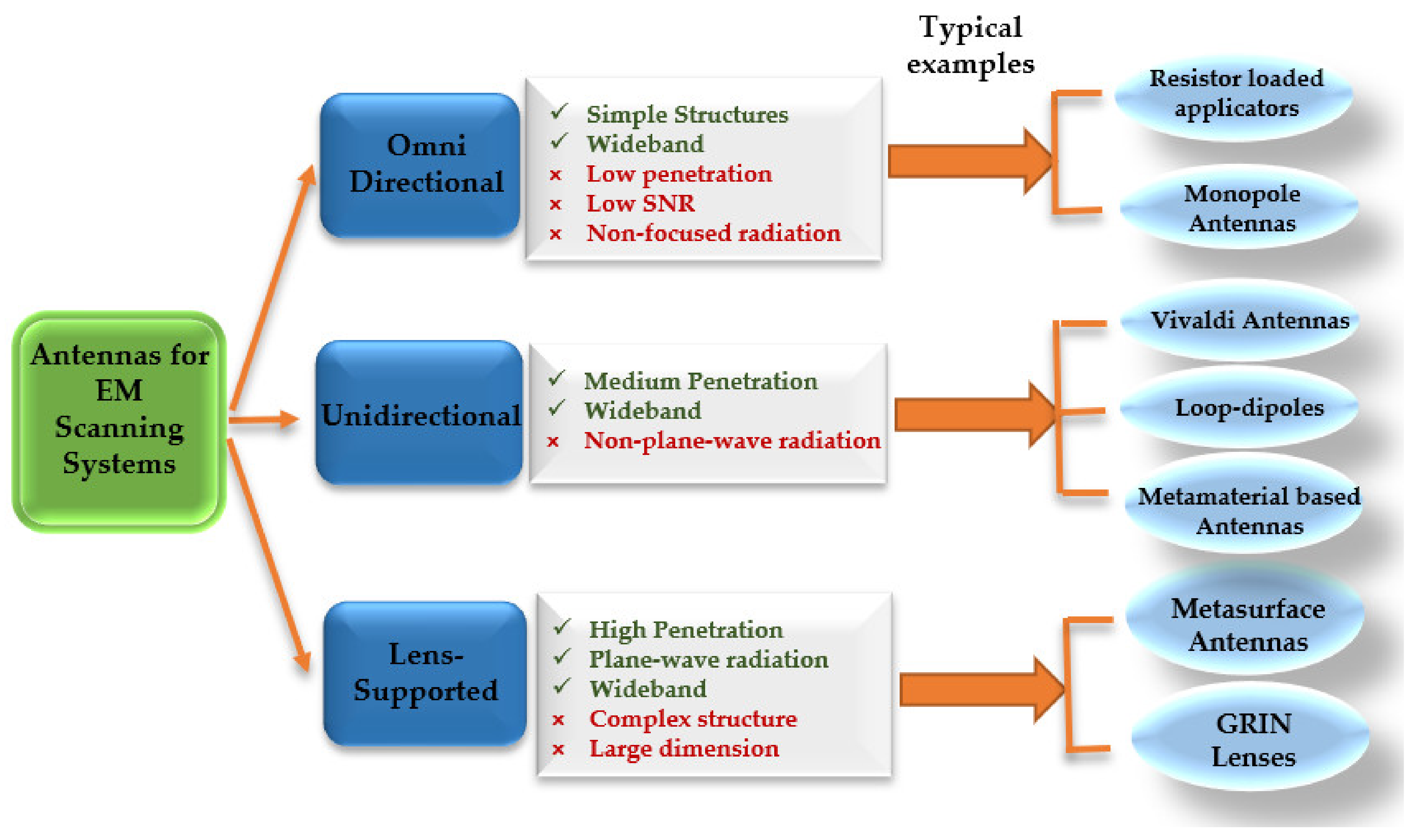
4. Antenna Designs
4.1. Antenna Design Criteria
4.2. Antenna Categories
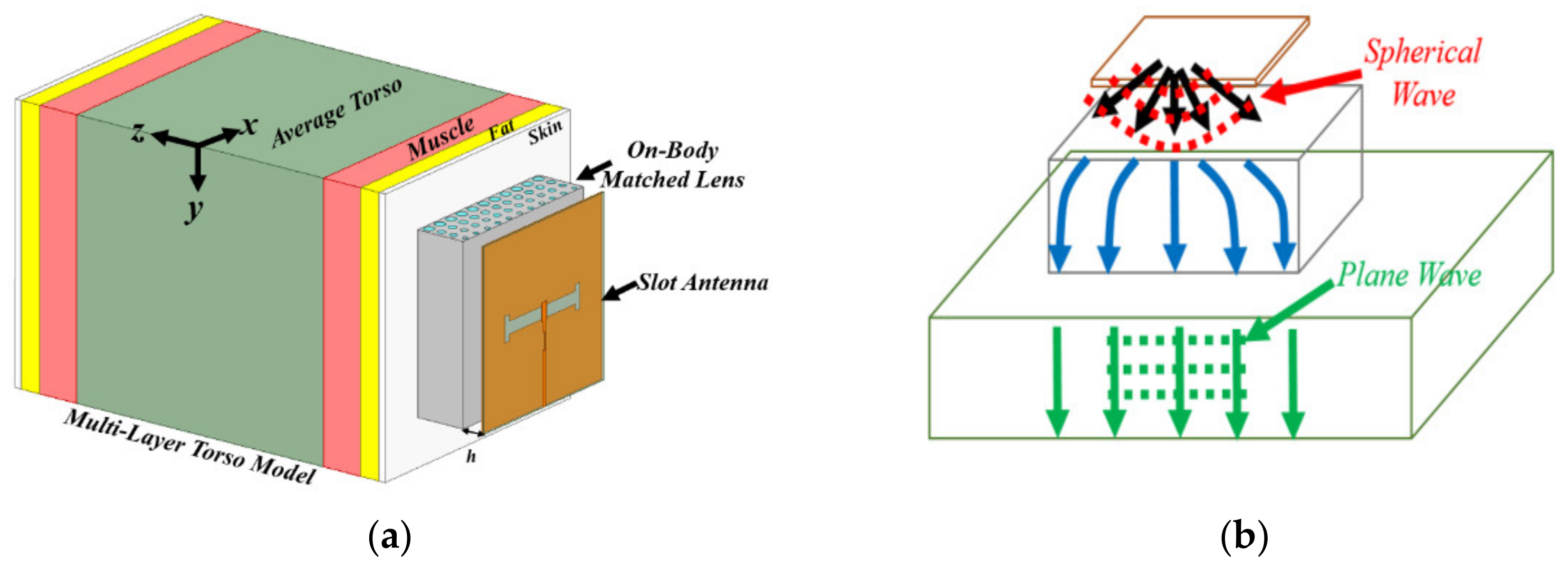
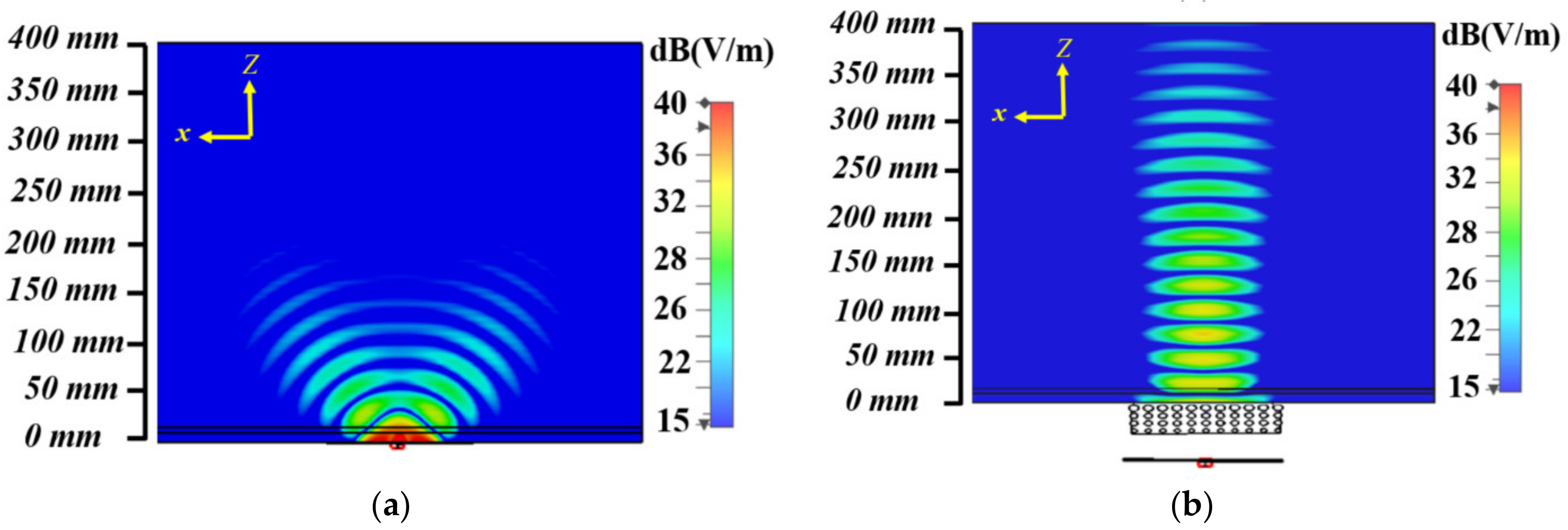
4.2.1. On-Body Matched Antennas
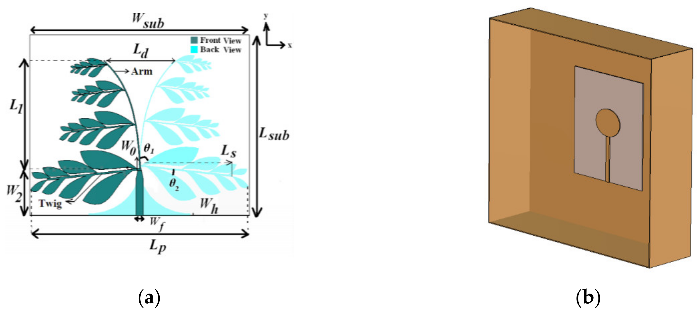
4.2.2. Free-Space Antennas
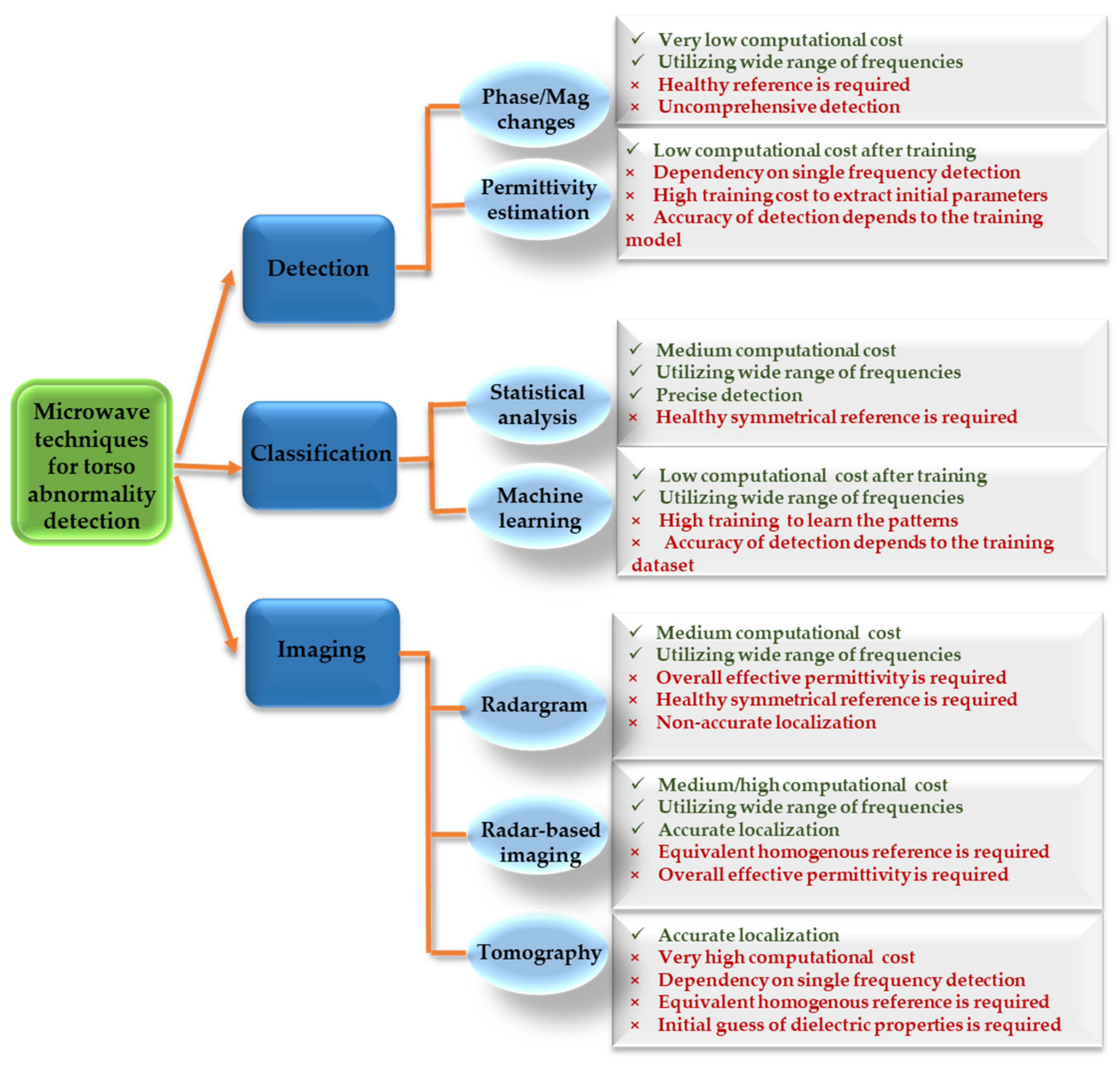
5. Microwave Detection Techniques
5.1. Detection Only Methods
5.1.1. Phase/Magnitude Changes
5.1.2. Effective Permittivity Estimation
5.2. Detection and Classification Methods
5.2.1. Statistical Analysis
5.2.2. Machine Learning
5.3. Detection and Localization Methods
5.3.1. Radargram
5.3.2. Radar-Based Imaging
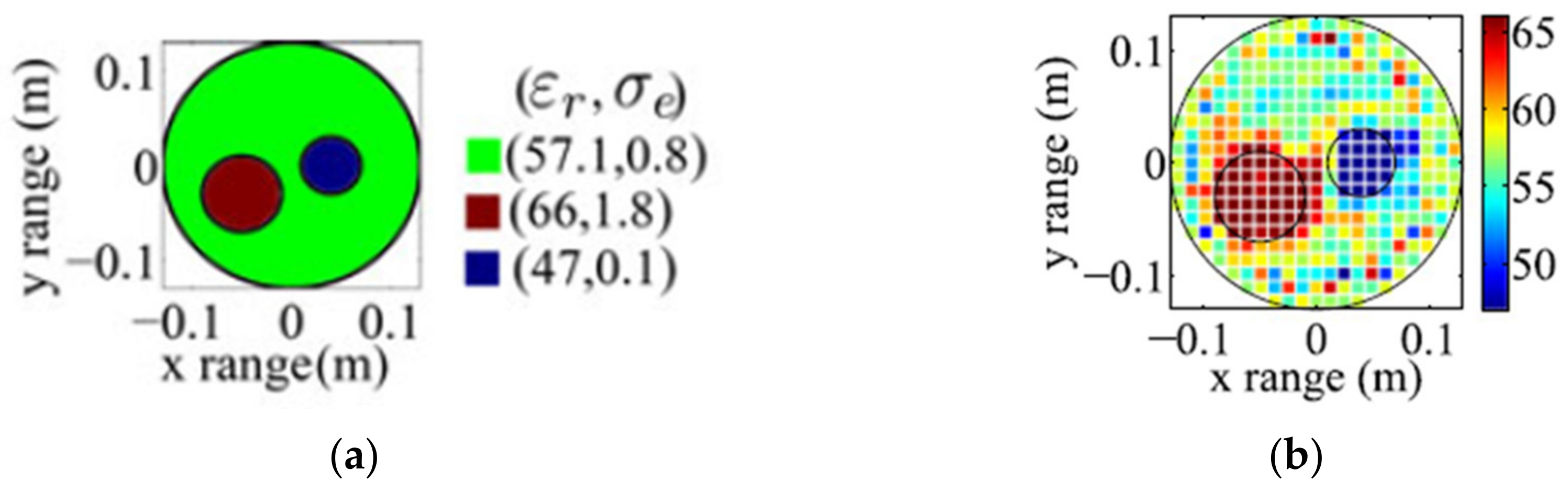
5.3.3. Tomography
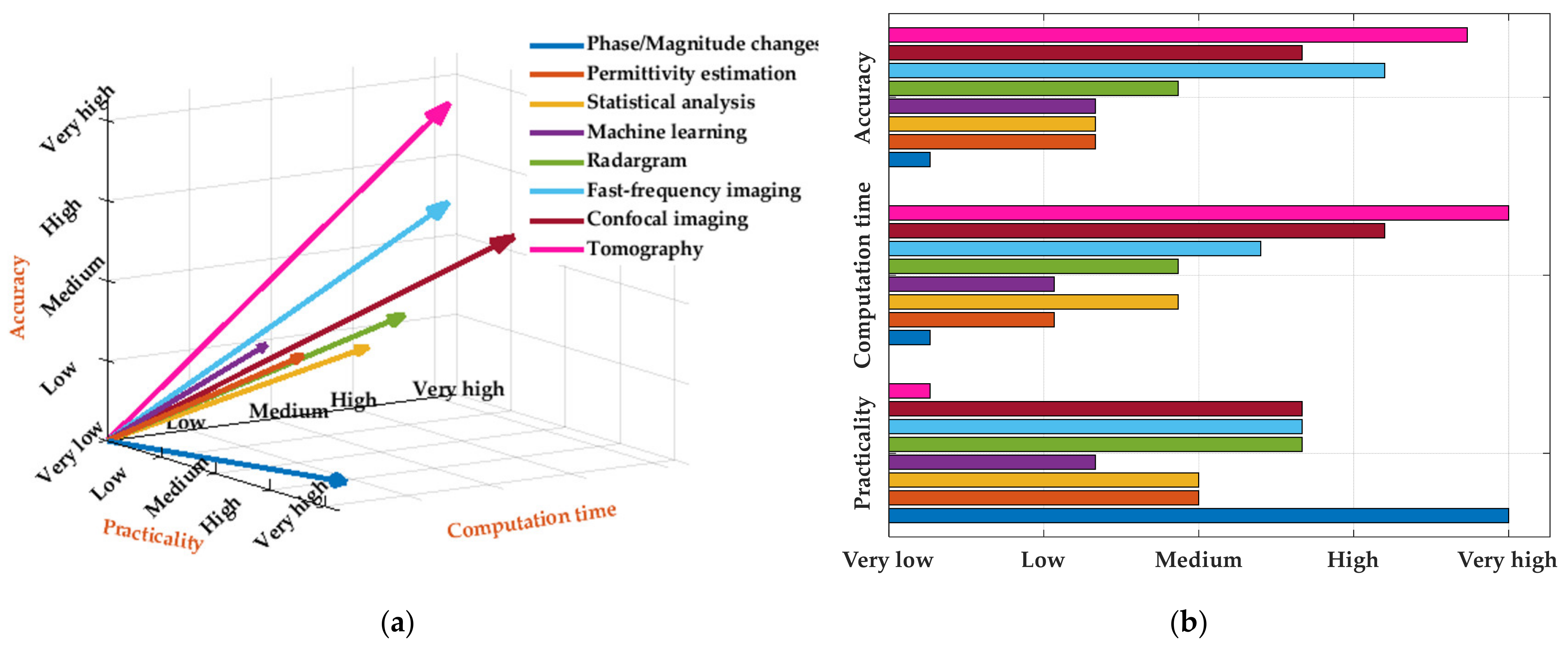
6. Conclusions
Funding
Institutional Review Board Statement
Informed Consent Statement
Data Availability Statement
Conflicts of Interest
References
- Johnson, C.C.; Guy, A.W. Nonionizing electromagnetic wave effects in biological materials and systems. Proc. IEEE 1972, 60, 692–718. [Google Scholar] [CrossRef]
- Ross, K.; Gordon, R.E. Water in malignant tissue, measured by cell refractometry and nuclear magnetic resonance. J. Microsc. 1982, 128, 7–21. [Google Scholar] [CrossRef] [PubMed]
- Khaltaev, N.; Axelrod, S. Chronic respiratory diseases global mortality trends, treatment guidelines, life style modifications, and air pollution: Preliminary analysis. J. Thorac. Dis. 2019, 11, 2643. [Google Scholar] [CrossRef] [PubMed]
- Gluecker, T.; Capasso, P.; Schnyder, P.; Gudinchet, F.; Schaller, M.-D.; Revelly, J.-P.; Chiolero, R.; Vock, P.; Wicky, S. Clinical and Radiologic Features of Pulmonary Edema. Radiographics 1999, 19, 1507–1531. [Google Scholar] [CrossRef] [PubMed]
- Spencer, H.; Pratt, P.C. Pathology of the Lung. Ann. Surg. 1980, 192, 135. [Google Scholar] [CrossRef]
- U.R., A.; Verma, K. Pulmonary Edema in COVID19—A Neural Hypothesis. ACS Chem. Neurosci. 2020, 11, 2048–2050. [Google Scholar] [CrossRef]
- Susskind, C. Possible use of microwaves in the management of lung disease. Proc. IEEE 1973, 61, 673–674. [Google Scholar] [CrossRef]
- Pedersen, P.; Johnson, C.; Durney, C.; Bragg, D. An investigation of the use of microwave radiation for pulmonary diagnostics. IEEE. Trans. Biomed. Eng. 1976, 410–412. [Google Scholar] [CrossRef]
- Pedersen, P.; Johnson, C.; Durney, C.; Bragg, D. Microwave reflection and transmission measurements for pulmonary diagnosis and monitoring. IEEE. Trans. Biomed. Eng. 1978, 25, 40–48. [Google Scholar] [CrossRef]
- Iskander, M.; Durney, C. Microwave methods of measuring changes in lung water. J. Microw. Power 1983, 18, 265–275. [Google Scholar] [CrossRef] [PubMed]
- Iskander, M.; Durney, C.; Shoff, D.; Bragg, D. Diagnosis of pulmonary edema by a surgically noninvasive microwave technique. Radio Sci. 1979, 14, 265–269. [Google Scholar] [CrossRef]
- Iskander, M.; Durney, C.; Grange, T.; Smith, C. Radiometric technique for measuring changes in lung water (short papers). IEEE Trans. Microwave Theory Tech. 1984, 32, 554–556. [Google Scholar] [CrossRef]
- Salman, S.; Wang, Z.; Colebeck, E.; Kiourti, A.; Topsakal, E.; Volakis, J.L. Pulmonary Edema Monitoring Sensor With Integrated Body-Area Network for Remote Medical Sensing. IEEE Trans. Antennas Propag. 2014, 62, 2787–2794. [Google Scholar] [CrossRef]
- Iskander, M.; Durney, C.; Bragg, D.; Ovard, B. A microwave method for estimating absolute value of average lung water. Radio Sci. 1982, 17, 111S–118S. [Google Scholar] [CrossRef]
- Rezaeieh, S.A.; Bialkowski, K.S.; Abbosh, A.M. Folding method for bandwidth and directivity enhancement of meandered loop ultra-high frequency antenna for heart failure detection system. IET Microw. Antennas Propag. 2014, 8, 1218–1227. [Google Scholar] [CrossRef]
- Zamani, A.; Rezaeieh, S.A.; Abbosh, A.M. Frequency domain method for early stage detection of congestive heart failure. In Proceedings of the 2014 IEEE MTT-S International Microwave Workshop Series on RF and Wireless Technologies for Biomedical and Healthcare Applications (IMWS-Bio2014), London, UK, 8–10 December 2014; pp. 1–3. [Google Scholar]
- Rezaeieh, S.A.; Abbosh, A.; Zamani, A.; Bialkowski, K. Pleural effusion detection system using wideband slot-loaded loop antenna. Electron. Lett. 2015, 51, 1144–1146. [Google Scholar] [CrossRef]
- Rezaeieh, S.A.; Zamani, A.; Bialkowski, K.S.; Mahmoud, A.; Abbosh, A.M. Feasibility of Using Wideband Microwave System for Non-Invasive Detection and Monitoring of Pulmonary Oedema. Sci. Rep. 2015, 5, 14047. [Google Scholar] [CrossRef]
- Zamani, A.; Rezaeieh, S.A.; Abbosh, A.M. Lung cancer detection using frequency-domain microwave imaging. Electron. Lett. 2015, 51, 740–741. [Google Scholar] [CrossRef]
- Babarinde, O.J.; Jamlos, M.F. UWB microwave imaging for lung tumor detection in a thorax model. In Proceedings of the 2014 IEEE Symposium on Wireless Technology and Applications (ISWTA), Kota Kinabalu, Malaysia, 28 September–1 October 2014; pp. 130–133. [Google Scholar]
- Babarinde, O.J.; Jamlos, M.F.; Soh, P.J.; Schreurs, D.M.M.-P.; Beyer, A. Microwave imaging technique for lung tumour detection. In Proceedings of the 2016 German Microwave Conference (GeMiC), Bochum, Germany, 14–16 March 2016; pp. 100–103. [Google Scholar]
- Caorsi, S.; Massa, A.; Pastorino, M.; Rosani, A. Microwave medical imaging: Potentialities and limitations of a stochastic optimization technique. IEEE Trans. Microwave Theory Tech. 2004, 52, 1909–1916. [Google Scholar] [CrossRef]
- Semenov, S.Y.; Bulyshev, A.E.; Souvorov, A.E.; Nazarov, A.G.; Sizov, Y.E.; Svenson, R.H.; Posukh, V.G.; Pavlovsky, A.; Repin, P.N.; Tatsis, G.P. Three-dimensional microwave tomography: Experimental imaging of phantoms and biological objects. IEEE Trans. Microw. Theory Techn. 2000, 48, 1071–1074. [Google Scholar] [CrossRef]
- Rezaeieh, S.A.; Brankovic, A.; Janani, A.S.; Mohammed, B.; Darvazehban, A.; Zamani, A.; Macdonald, G.A.; Abbosh, A.M. Wearable Electromagnetic Belt for Steatotic Liver Detection Using Multivariate Energy Statistics. IEEE Access 2020, 8, 201847–201860. [Google Scholar] [CrossRef]
- Zhang, H.; Li, M.; Yang, F.; Xu, S.; Yin, Y.; Zhou, H.; Yang, Y.; Zeng, S.; Shao, J. A Feasibility Study of 2-D Microwave Thorax Imaging Based on the Supervised Descent Method. Electron. Lett. 2021, 10, 352. [Google Scholar]
- Rezaeieh, S.A.; Bialkowski, K.S.; Abbosh, A.M. Microwave System for the Early Stage Detection of Congestive Heart Failure. IEEE Access 2014, 2, 921–929. [Google Scholar] [CrossRef]
- Brankovic, A.; Zamani, A.; Abbosh, A. Electromagnetic based fatty liver detection using machine learning. In Proceedings of the 2019 13th European Conference on Antennas and Propagation (EuCAP), Krakow, Poland, 31 March–5 April 2019; pp. 1–3. [Google Scholar]
- Fear, E.C.; Bourqui, J.; Curtis, C.; Mew, D.; Docktor, B.; Romano, C. Microwave Breast Imaging With a Monostatic Radar-Based System: A Study of Application to Patients. IEEE Trans. Microwave Theory Tech. 2013, 61, 2119–2128. [Google Scholar] [CrossRef]
- Ahdi Rezaeieh, S.; Zamani, A.; Bialkowski, K.S.; Abbosh, A.M. Novel Microwave Torso Scanner for Thoracic Fluid Accumulation Diagnosis and Monitoring. Sci. Rep. 2017, 7, 304. [Google Scholar] [CrossRef]
- Celik, N.; Gagarin, R.; Huang, G.C.; Iskander, M.F.; Berg, B.W. Microwave Stethoscope: Development and Benchmarking of a Vital Signs Sensor Using Computer-Controlled Phantoms and Human Studies. IEEE. Trans. Biomed. Eng. 2014, 61, 2341–2349. [Google Scholar] [CrossRef] [PubMed]
- Celik, N.; Gagarin, R.; Youn, H.; Iskander, M.F. A Noninvasive Microwave Sensor and Signal Processing Technique for Continuous Monitoring of Vital Signs. IEEE Antennas Wirel. Propag. Lett. 2011, 10, 286–289. [Google Scholar] [CrossRef]
- Perron, R.R.; Huang, G.C.; Iskander, M.F. Textile electromagnetic coupler for monitoring vital signs and changes in lung water content. IEEE Antennas Wirel. Propag. Lett. 2014, 14, 151–154. [Google Scholar] [CrossRef]
- Ahdi Rezaeieh, S.; Zamani, A.; Bialkowski, K.S.; Macdonald, G.A.; Abbosh, A.M. Three-Dimensional Electromagnetic Torso Scanner. Sensors 2019, 19, 1015. [Google Scholar] [CrossRef]
- Rezaeieh, S.A.; Zamani, A.; Bialkowski, K.S.; Abbosh, A.M. Foam Embedded Wideband Antenna Array for Early Congestive Heart Failure Detection With Tests Using Artificial Phantom With Animal Organs. IEEE Trans. Antennas Propag. 2015, 63, 5138–5143. [Google Scholar] [CrossRef]
- Rezaeieh, S.A.; Bialkowski, K.; Abbosh, A. Three-dimensional open-ended slot antenna for heart failure detection system employing differential technique. IEEE Antennas Wirel. Propag. Lett. 2014, 13, 1753–1756. [Google Scholar] [CrossRef]
- Rezaeieh, S.A.; Bialkowski, K.S.; Zamani, A.; Abbosh, A.M. Loop-Dipole Composite Antenna for Wideband Microwave-Based Medical Diagnostic Systems With Verification on Pulmonary Edema Detection. IEEE Antennas Wirel. Propag. Lett. 2016, 15, 838–841. [Google Scholar] [CrossRef]
- Zhang, S.; Xu, G.; Zhang, X.; Zhang, B.; Wang, H.; Xu, Y.; Yin, N.; Li, Y.; Yan, W. Computation of a 3-D Model for Lung Imaging With Electrical Impedance Tomography. IEEE Trans. Magn. 2012, 48, 651–654. [Google Scholar] [CrossRef]
- Darvazehban, A.; Rezaeieh, S.A.; Zamani, A.; Abbosh, A.M. Pattern Reconfigurable Metasurface Antenna for Electromagnetic Torso Imaging. IEEE Trans. Antennas Propag. 2019, 67, 5453–5462. [Google Scholar] [CrossRef]
- Blauert, J.; Kiourti, A. Bio-Matched Antennas With Flare Extensions for Reduced Low Frequency Cutoff. IEEE Open J. Antennas Propag. 2020, 1, 136–141. [Google Scholar] [CrossRef]
- Zhang, H.; Li, M.; Yang, F.; Xu, S.; Zhou, H.; Yang, Y.; Chen, L. A Low-Profile Compact Dual-Band L-Shape Monopole Antenna for Microwave Thorax Monitoring. IEEE Antennas Wirel. Propag. Lett. 2020, 19, 448–452. [Google Scholar] [CrossRef]
- Specific Absorption Rate (SAR) for Cellular Telephones. Available online: https://www.fcc.gov/general/specific-absorption-rate-sar-cellular-telephones (accessed on 1 April 2021).
- On the Limitation of Exposure of the General Public to Electromagnetic Fields (0 Hz to 300 GHz). Available online: https://eur-lex.europa.eu/legal-content/EN/TXT/PDF/?uri=CELEX:31999H0519&from=EN (accessed on 1 April 2021).
- Rezaeieh, S.A.; Sorbello, K.; Abbosh, A. Specific absorption rate in human torso from microwave-based heart failure detection systems. In Proceedings of the 2014 IEEE Antennas and Propagation Society International Symposium (APSURSI), Memphis, TN, USA, 6–11 July 2014; pp. 518–519. [Google Scholar]
- Alqadami, A.S.M.; Nguyen-Trong, N.; Mohammed, B.; Stancombe, A.E.; Heitzmann, M.T.; Abbosh, A. Compact Unidirectional Conformal Antenna Based on Flexible High-Permittivity Custom-Made Substrate for Wearable Wideband Electromagnetic Head Imaging System. IEEE Trans. Antennas Propag. 2020, 68, 183–194. [Google Scholar] [CrossRef]
- Tissue properties database, The Foundation for Research on Information Technologies in Society (IT’IS). Available online: https://itis.swiss/virtual-population/tissue-properties/database/tissue-frequency-chart/ (accessed on 1 April 2021).
- Rezaeieh, S.A.; Tan, Y.-Q.; Abbosh, A.M.; Antoniades, M.A. Equivalent circuit model for finding the optimum frequency range for the detection of heart failure using microwave systems. In Proceedings of the 2013 IEEE Antennas and Propagation Society International Symposium (APSURSI), Lake Buena Vista, FL, USA, 7–13 July 2013; pp. 2059–2060. [Google Scholar]
- Mobashsher, A.T.; Abbosh, A. On-site rapid diagnosis of intracranial hematoma using portable multi-slice microwave imaging system. Sci. Rep. 2016, 6, 1–17. [Google Scholar] [CrossRef]
- Rezaeieh, S.A.; Zamani, A.; Bialkowski, K.S.; Abbosh, A.M. Unidirectional Slot-Loaded Loop Antenna With Wideband Performance and Compact Size for Congestive Heart Failure Detection. IEEE Trans. Antennas Propag. 2015, 63, 4557–4562. [Google Scholar] [CrossRef]
- Zamani, A.; Abbosh, A.M.; Mobashsher, A.T. Fast Frequency-Based Multistatic Microwave Imaging Algorithm With Application to Brain Injury Detection. IEEE Trans. Microwave Theory Tech. 2016, 64, 653–662. [Google Scholar] [CrossRef]
- Babarinde, O.J.; Jamlos, M.F.; Ramli, N.B. UWB microwave imaging of the lungs: A review. In Proceedings of the 2014 IEEE 2nd International Symposium on Telecommunication Technologies (ISTT), Langkawi Island, Malaysia, 24–26 November 2014; pp. 188–193. [Google Scholar]
- Bayat, N.; Mojabi, P. On the use of focused incident near-field beams in microwave imaging. Sensors 2018, 18, 3127. [Google Scholar] [CrossRef] [PubMed]
- Mobashsher, A.T.; Abbosh, A.M. Performance comparison of directional and omnidirectional ultra-wideband antennas in near-field microwave head imaging systems. In Proceedings of the 2016 International Conference on Electromagnetics in Advanced Applications (ICEAA), Queensland, Australia, 19–23 September 2016; pp. 804–807. [Google Scholar]
- Kumar, A.; Badhai, R.K. A novel compact printed wideband on-body monopole antenna for the diagnosis of heart failure detection. Int. J. Control Theory Appl. 2017, 10, 207–217. [Google Scholar]
- Rezaeieh, S.A.; Darvazehban, A.; Khosravi-Farsani, M.; Abbosh, A. Body-Matched Gradient Index Lens Antenna for Electromagnetic Torso Scanner. IEEE Trans. Antennas Propag. 2021, 1. [Google Scholar] [CrossRef]
- Moll, J.; Vrba, J.; Merunka, I.; Fiser, O.; Krozer, V. Non-invasive microwave lung water monitoring: Feasibility study. In Proceedings of the 2015 9th European Conference on Antennas and Propagation (EuCAP), Lisbon, Portugal, 13–17 April 2015; pp. 1–4. [Google Scholar]
- Figueredo, R.E.; De Oliveira, A.M.; Nurhayati, N.; Neto, A.M.D.O.; Nogueira, I.C.; Justo, J.F.; Perotoni, M.B.; De Carvalho, A. A vivaldi antenna palm tree class with koch square fractal slot edge for near-field microwave biomedical imaging applications. In Proceedings of the 2020 Third International Conference on Vocational Education and Electrical Engineering (ICVEE), Surabaya, Indonesia, 3–4 October 2020; pp. 1–6. [Google Scholar]
- Rezaeieh, S.A.; Abbosh, A.M. Compact Planar Loop–Dipole Composite Antenna With Director for Bandwidth Enhancement and Back Radiation Suppression. IEEE Trans. Antennas Propag. 2016, 64, 3723–3728. [Google Scholar] [CrossRef]
- Rezaeieh, S.A.; Abbosh, A.; Wang, Y. Wideband unidirectional antenna of folded structure in microwave system for early detection of congestive heart failure. IEEE Trans. Antennas Propag. 2014, 62, 5375–5381. [Google Scholar] [CrossRef]
- Darvazehban, A.; Rezaeieh, S.A.; Abbosh, A.M. Programmable Metasurface Antenna for Electromagnetic Torso Scanning. IEEE Access 2020, 8, 166801–166812. [Google Scholar] [CrossRef]
- Rezaeieh, S.A.; Antoniades, M.A.; Abbosh, A.M. Compact Wideband Loop Antenna Partially Loaded With Mu-Negative Metamaterial Unit Cells for Directivity Enhancement. IEEE Antennas Wirel. Propag. Lett. 2016, 15, 1893–1896. [Google Scholar] [CrossRef]
- Li, M.; Luk, K. A Differential-Fed Magneto-Electric Dipole Antenna for UWB Applications. IEEE Trans. Antennas Propag. 2013, 61, 92–99. [Google Scholar] [CrossRef]
- Ge, L.; Luk, K.M. A Magneto-Electric Dipole for Unidirectional UWB Communications. IEEE Trans. Antennas Propag. 2013, 61, 5762–5765. [Google Scholar] [CrossRef]
- Yan, S.; Soh, P.J.; Vandenbosch, G.A.E. Wearable Dual-Band Magneto-Electric Dipole Antenna for WBAN/WLAN Applications. IEEE Trans. Antennas Propag. 2015, 63, 4165–4169. [Google Scholar] [CrossRef]
- Lu, W.; Liu, G.; Tong, K.F.; Zhu, H. Dual-Band Loop-Dipole Composite Unidirectional Antenna for Broadband Wireless Communications. IEEE Trans. Antennas Propag. 2014, 62, 2860–2866. [Google Scholar] [CrossRef]
- Islam, M.T.; Mahmud, M.Z.; Misran, N.; Takada, J.; Cho, M. Microwave Breast Phantom Measurement System With Compact Side Slotted Directional Antenna. IEEE Access 2017, 5, 5321–5330. [Google Scholar] [CrossRef]
- Biswas, B.; Ghatak, R.; Poddar, D.R. A Fern Fractal Leaf Inspired Wideband Antipodal Vivaldi Antenna for Microwave Imaging System. IEEE Trans. Antennas Propag. 2017, 65, 6126–6129. [Google Scholar] [CrossRef]
- Wang, Z.; Zhang, H. Improvements in a high gain UWB antenna with corrugated edges. Prog. Electromagn. Res. 2009, 6, 159–166. [Google Scholar] [CrossRef][Green Version]
- Manoochehri, O.; Farzami, F.; Erricolo, D.; Chen, P.-Y.; Darvazehban, A.; Shamim, A.; Bagci, H. Design of a corrugated antipodal Vivaldi antenna with stable pattern. In Proceedings of the 2019 United States National Committee of URSI National Radio Science Meeting (USNC-URSI NRSM), Boulder, CO, USA, 9–12 January 2019; pp. 1–2. [Google Scholar]
- Christopoulou, M.; Koulouridis, S. Inter-subject variability evaluation towards a robust microwave sensor for pneumothorax diagnosis. Prog. Electromagn. Res. 2015, 42, 61–70. [Google Scholar] [CrossRef]
- Christopoulou, M.I.; Koulouridis, S.D. Dual patch antenna sensor for pneumothorax diagnosis: Sensitivity and performance study. In Proceedings of the 2014 36th Annual International Conference of the IEEE Engineering in Medicine and Biology Society, Chicago, IL, USA, 26–30 August 2014; Volume 2014, pp. 4827–4830. [Google Scholar]
- Ameer, W.; Awan, D.; Bashir, S.; Waheed, A. Use of directional UWB antenna for lung tumour detection. In Proceedings of the 2019 2nd International Conference on Advancements in Computational Sciences (ICACS), Lahore, Pakistan, 18–20 February 2019; pp. 1–5. [Google Scholar]
- Rezaeieh, S.A.; Abbosh, A. Wideband and unidirectional folded antenna for heart failure detection system. IEEE Antennas Wirel. Propag. Lett. 2014, 13, 844–847. [Google Scholar] [CrossRef]
- Zhang, H.; Chen, X.; Li, M.; Yang, F.; Xu, S. A compact dual-band folded-cavity antenna for microwave biomedical imaging applications. In Proceedings of the 2019 IEEE International Conference on Computational Electromagnetics (ICCEM), Shanghai, China, 20–22 March 2019; pp. 1–3. [Google Scholar]
- Rezaeieh, S.A.; Antoniades, M.A.; Abbosh, A.M. Bandwidth and Directivity Enhancement of Loop Antenna by Nonperiodic Distribution of Mu-Negative Metamaterial Unit Cells. IEEE Trans. Antennas Propag. 2016, 64, 3319–3329. [Google Scholar] [CrossRef]
- Rezaeieh, S.A.; Antoniades, M.A.; Abbosh, A.M. Miniaturization of Planar Yagi Antennas Using Mu-Negative Metamaterial-Loaded Reflector. IEEE Trans. Antennas Propag. 2017, 65, 6827–6837. [Google Scholar] [CrossRef]
- Rezaeieh, S.A.; Zamani, A.; Abbosh, A. Thoracic fluid detection and monitoring system using metamaterial loaded Yagi-antenna array. In Proceedings of the 2016 International Conference on Electromagnetics in Advanced Applications (ICEAA), Cairns, Australia, 19–23 September 2016; pp. 642–645. [Google Scholar]
- Rezaeieh, S.A.; Zamani, A.; Abbosh, A.M. Pattern Reconfigurable Wideband Loop Antenna for Thorax Imaging. IEEE Trans. Antennas Propag. 2019, 67, 5104–5114. [Google Scholar] [CrossRef]
- Darvazehban, A.; Rezaeieh, S.A.; Abbosh, A. Pattern-Reconfigurable Loop–Dipole Antenna for Electromagnetic Pleural Effusion Detection. IEEE Trans. Antennas Propag. 2020, 68, 5955–5964. [Google Scholar] [CrossRef]
- Darvazehban, A.; Rezaeieh, S.A.; Manoochehri, O.; Abbosh, A.M. Two-Dimensional Pattern-Reconfigurable Cross-Slot Antenna With Inductive Reflector for Electromagnetic Torso Imaging. IEEE Trans. Antennas Propag. 2020, 68, 703–711. [Google Scholar] [CrossRef]
- Bond, E.J.; Xu, L.; Hagness, S.C.; Veen, B.D.V. Microwave imaging via space-time beamforming for early detection of breast cancer. IEEE Trans. Antennas Propag. 2003, 51, 1690–1705. [Google Scholar] [CrossRef]
- Dem’yanenko Alexander, V. Investigation on resolution of applicator antenna for device for non-invasive bronchopulmonary diseases diagnosis. In Proceedings of the 2020 IEEE Conference of Russian Young Researchers in Electrical and Electronic Engineering (EIConRus), Moscow and St. Petersburg, Russia, 27–30 January 2020; pp. 1498–1502. [Google Scholar]
- Semernik, I.V.; Dem’Yanenko, A.V.; Semernik, O.E.; Lebedenko, A.A. Non-invasive method for bronchopulmonary diseases diagnosis in patients of all ages based on the microwave technologies. In Proceedings of the 2017 IEEE Conference of Russian Young Researchers in Electrical and Electronic Engineering (EIConRus), Moscow and St. Petersburg, Russia, 1–3 February 2017; pp. 78–81. [Google Scholar]
- Semernik, I.V.; Dem’Yanenko, A.V.; Topalov, F.S.; Samonova, C.V.; Semernik, O.E.; Lebedenko, A.A. Bronchial asthma diagnosis device based on microwave technologies. In Proceedings of the 2017 Radiation and Scattering of Electromagnetic Waves (RSEMW), Divnomorskoe, Russia, 26–30 June 2017; pp. 275–278. [Google Scholar]
- Camacho, L.M.; Tjuatja, S. FDTD simulation of microwave scattering from a lung tumor. In Proceedings of the 2005 IEEE Antennas and Propagation Society International Symposium, Washington, DC, USA, 3–8 July 2005; Volume 3, pp. 815–818. [Google Scholar]
- Alhawari, A. Lung tumour detection using ultra-wideband microwave imaging approach. J. Fundam. Appl. Sci. 2018, 10, 222–234. [Google Scholar]
- Zamani, A.; Abbosh, A.M. Estimation of frequency dispersive complex permittivity seen by each antenna for enhanced multistatic radar medical imaging. IEEE Trans. Antennas Propag. 2017, 65, 3702–3711. [Google Scholar] [CrossRef]
- Zamani, A.; Darvazehban, A.; Rezaeieh, S.A.; Abbosh, A. Three-dimensional electromagnetic torso imaging using reconfigurable antennas. In Proceedings of the 2019 13th European Conference on Antennas and Propagation (EuCAP), Krakow, Poland, 31 March–5 April 2019; pp. 1–3. [Google Scholar]
- Guo, L.; Abbosh, A.M. Optimization-based confocal microwave imaging in medical applications. IEEE Trans. Antennas Propag. 2015, 63, 3531–3539. [Google Scholar] [CrossRef]
- Rocca, P.; Benedetti, M.; Donelli, M.; Franceschini, D.; Massa, A. Evolutionary optimization as applied to inverse scattering problems. Inverse Probl. 2009, 25, 1–41. [Google Scholar] [CrossRef]
- Caorsi, S.; Massa, A.; Pastorino, M. A computational technique based on a real-coded genetic algorithm for microwave imaging purposes. IEEE Trans. Geosci. Remote Sens. 2000, 38, 1697–1708. [Google Scholar] [CrossRef]
- Chew, W.C.; Wang, Y.-M. Reconstruction of two-dimensional permittivity distribution using the distorted Born iterative method. IEEE Trans. Med. Imag. 1990, 9, 218–225. [Google Scholar] [CrossRef]
- Guo, L.; Abbosh, A.M. Microwave imaging of nonsparse domains using Born iterative method with wavelet transform and block sparse Bayesian learning. IEEE Trans. Antennas Propag. 2015, 63, 4877–4888. [Google Scholar] [CrossRef]
- Souvorov, A.E.; Bulyshev, A.E.; Semenov, S.Y.; Svenson, R.H.; Nazarov, A.G.; Sizov, Y.E.; Tatsis, G.P. Microwave tomography: A two-dimensional Newton iterative scheme. IEEE Trans. Microw. Theory Tech. 1998, 46, 1654–1659. [Google Scholar] [CrossRef]
- De Zaeytijd, J.; Franchois, A.; Eyraud, C.; Geffrin, J.-M. Full-wave three-dimensional microwave imaging with a regularized Gauss–Newton method—Theory and experiment. IEEE Trans. Antennas Propag. 2007, 55, 3279–3292. [Google Scholar] [CrossRef]
- Harada, H.; Wall, D.J.; Takenaka, T.; Tanaka, M. Conjugate gradient method applied to inverse scattering problem. IEEE Trans. Antennas Propag. 1995, 43, 784–792. [Google Scholar] [CrossRef]
- Semenov, S. Microwave tomography: Review of the progress towards clinical applications. Philos Trans. A Math. Phys. Eng. Sci. 2009, 367, 3021–3042. [Google Scholar] [CrossRef] [PubMed]
- Semenov, S.; Pham, N.; Egot-Lemaire, S. Ferroelectric nanoparticles for contrast enhancement microwave tomography: Feasibility assessment for detection of lung cancer. In Proceedings of the 1st World Congress on Electroporation and Pulsed Electric Fields in Biology, Medicine and Food & Environmental Technologies, Portorož, Slovenia, 6–10 September 2015; Volume 25, pp. 311–313. [Google Scholar]
- Semenov, S.; Posukh, V.; Bulyshev, A.; Williams, T.; Sizov, Y.; Repin, P.; Souvorov, A.; Nazarov, A. Microwave tomographic imaging of the heart in intact swine. J. Electromagn. Waves Appl. 2006, 20, 873–890. [Google Scholar] [CrossRef]
- Semenov, S.Y.; Bulyshev, A.E.; Posukh, V.G.; Sizov, Y.E.; Williams, T.C.; Souvorov, A.E. Microwave tomography for detection/imaging of myocardial infarction. I. Excised canine hearts. Ann. Biomed. Eng. 2003, 31, 262–270. [Google Scholar] [CrossRef] [PubMed]
- Chandra, R.; Johansson, A.J.; Gustafsson, M.; Tufvesson, F. A microwave imaging-based technique to localize an in-body RF source for biomedical applications. IEEE. Trans. Biomed. Eng. 2014, 62, 1231–1241. [Google Scholar] [CrossRef]
- Semenov, S.Y.; Svenson, R.H.; Bulyshev, A.E.; Souvorov, A.E.; Nazarov, A.G.; Sizov, Y.E.; Pavlovsky, A.V.; Borisov, V.Y.; Voinov, B.A.; Simonova, G.I. Three-dimensional microwave tomography: Experimental prototype of the system and vector Born reconstruction method. IEEE. Trans. Biomed. Eng. 1999, 46, 937–946. [Google Scholar] [CrossRef] [PubMed]


| Ref. | System Configuration | Antenna | Algorithm | Advantages | Disadvantages |
|---|---|---|---|---|---|
| [34] | Linear array of antenna in multi-static data acquisition mode | Unidirectional wideband free space 3-D loop-monopole antenna | Fast frequency imaging | •High accuracy of detection and localization •High practicality •Medium computation time | •Requirement of healthy symmetrical reference •Requirement of average permittivity of tissues •Medium penetration |
| [26,35] | Linear array of antenna in mono-static data acquisition mode | Unidirectional wideband free space folded antenna | Radargram | •High practicality •Medium computation time | •Requirement of healthy symmetrical reference •Requirement of average permittivity of tissues •Not suitable for deep target detection •Medium penetration |
| [27] | Mono-static data acquisition mode | Unidirectional wideband on-body matched waveguide antenna | Machine learning | •Low computation time after training •Simple structure | •Requirement of training •Low practicality •Not suitable for deep target detection |
| [29] | Circular array of antenna in multi-static data acquisition mode | Unidirectional wideband free space metamaterial unit-cell loaded Yagi-antenna | Fast frequency imaging | •High accuracy of detection and localization •High practicality Medium computation time | •Requirement of average permittivity of tissues •Medium penetratio |
| [31,32,70] | Bi-static data acquisition mode | Omni directional narrowband on-body matched antenna | Phase/Mag changes | •High practicality •Low computation time | •Low accuracy •Low penetration |
| [33] | Circular array of antenna in multi-static data acquisition mode | Unidirectional wideband free space resonance-based reflector antenna | Fast frequency imaging | •High accuracy of •High practicality •Medium computation time | •Requirement of average permittivity of tissues •Medium penetration •Complex setup |
| [36] | Circular array of antenna in mono-static data acquisition mode | Unidirectional wideband free space loop- dipole antenna | Fast frequency imaging | •High accuracy •High practicality •Medium computation time | •Requirement of average permittivity of tissues •Medium penetration •Not suitable for deep target detection |
| [38,59,87] | Quasi-circular antenna in mono-static data acquisition mode | Unidirectional wideband free space pattern reconfigurable metasurface antenna | Fast frequency imaging | •High accuracy •High practicality •Medium computation time •High penetration | •Requirement of average permittivity of tissues |
| [24] | Circular antenna in multi-static data acquisition mode | Unidirectional wideband on-body matched loop-dipole antenna | Statistical analyses | •Medium practicality •Medium computation time | •Requirement of a symmetric healthy part •Low-medium accuracy •Requirement of healthy threshold •Medium penetration |
| [86] | Circular antenna in multi-static data acquisition mode | Unidirectional wideband free space loop-dipole antenna | Permittivity estimation | •Medium practicality •Low computation time •Suitable for enhancing radar-based imaging | •Requirement of training •Low-medium accuracy •Medium penetration |
| [21,56] | Linear scanning monostatic data acquisition mode | Unidirectional wideband free space Vivaldi antenna | Radargram | •High practicality •Low computation time | •Not suitable for deep target detection •Medium penetration |
| [21] | Linear scanning mono-static data acquisition mode | UWB Antenna Free Space Antenna | Confocal imaging | •High practicality •Low computation time | •Low accuracy •Requirement of average permittivity of tissues •Not suitable for deep target detection •Low penetration |
| [23,98,101] | Quasi-circular antenna in multi-static data acquisition mode | Dielectric Loaded Waveguide | Tomography | •High accuracy •High penetration | •Low practicality •Very high computation time |
Publisher’s Note: MDPI stays neutral with regard to jurisdictional claims in published maps and institutional affiliations. |
© 2021 by the authors. Licensee MDPI, Basel, Switzerland. This article is an open access article distributed under the terms and conditions of the Creative Commons Attribution (CC BY) license (https://creativecommons.org/licenses/by/4.0/).
Share and Cite
Ahdi Rezaeieh, S.; Darvazehban, A.; Janani, A.S.; Abbosh, A.M. Electromagnetic Torso Scanning: A Review of Devices, Algorithms, and Systems. Biosensors 2021, 11, 135. https://doi.org/10.3390/bios11050135
Ahdi Rezaeieh S, Darvazehban A, Janani AS, Abbosh AM. Electromagnetic Torso Scanning: A Review of Devices, Algorithms, and Systems. Biosensors. 2021; 11(5):135. https://doi.org/10.3390/bios11050135
Chicago/Turabian StyleAhdi Rezaeieh, Sasan, Amin Darvazehban, Azin S. Janani, and Amin M. Abbosh. 2021. "Electromagnetic Torso Scanning: A Review of Devices, Algorithms, and Systems" Biosensors 11, no. 5: 135. https://doi.org/10.3390/bios11050135
APA StyleAhdi Rezaeieh, S., Darvazehban, A., Janani, A. S., & Abbosh, A. M. (2021). Electromagnetic Torso Scanning: A Review of Devices, Algorithms, and Systems. Biosensors, 11(5), 135. https://doi.org/10.3390/bios11050135