Conversion of Black Carbon Emitted from Diesel-Powered Merchant Ships to Novel Conductive Carbon Black as Anodic Material for Lithium Ion Batteries


Abstract
:1. Introduction
2. Materials and Methods
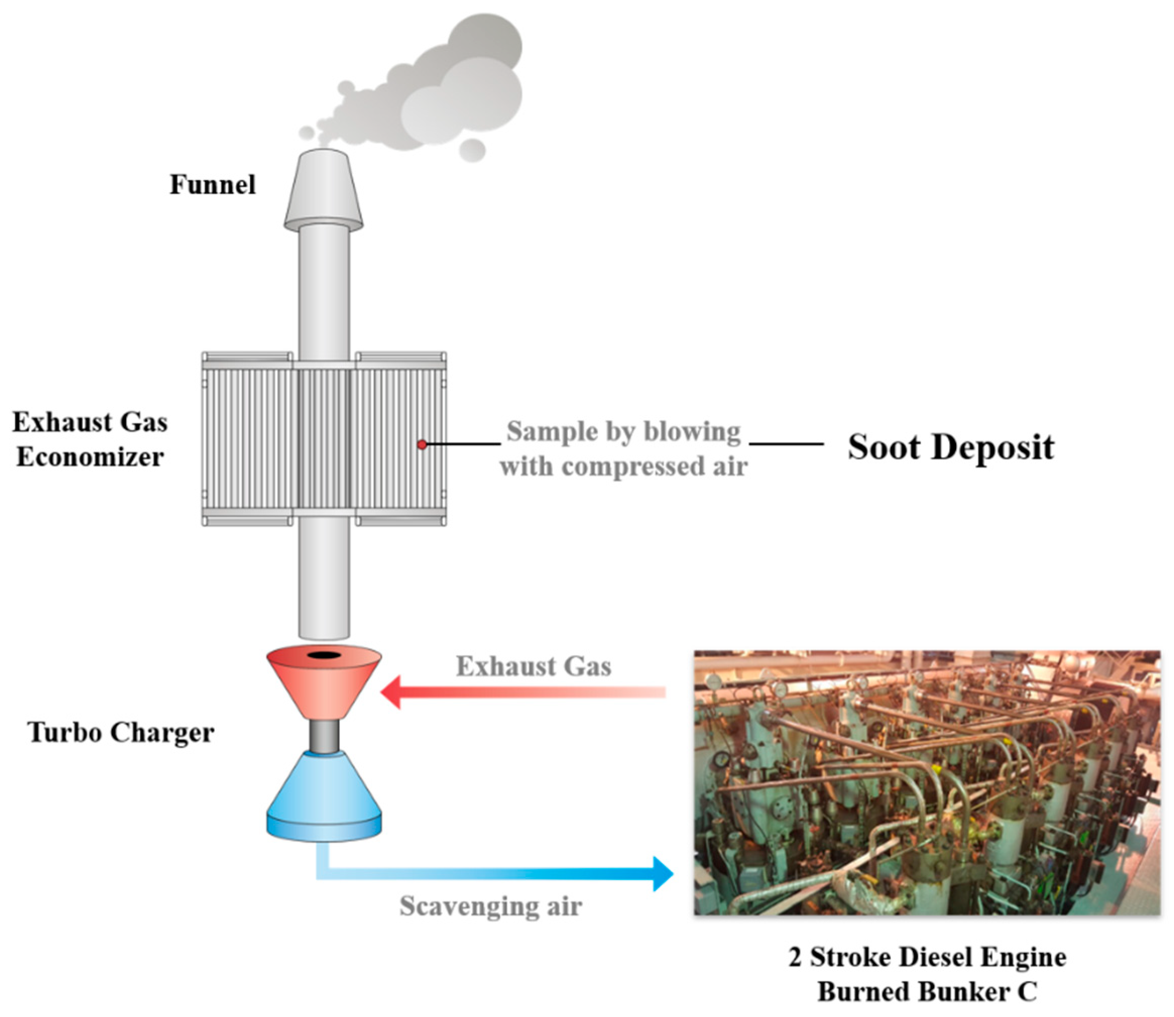
2.1. Sampling
2.2. Heat Treatment Procedure
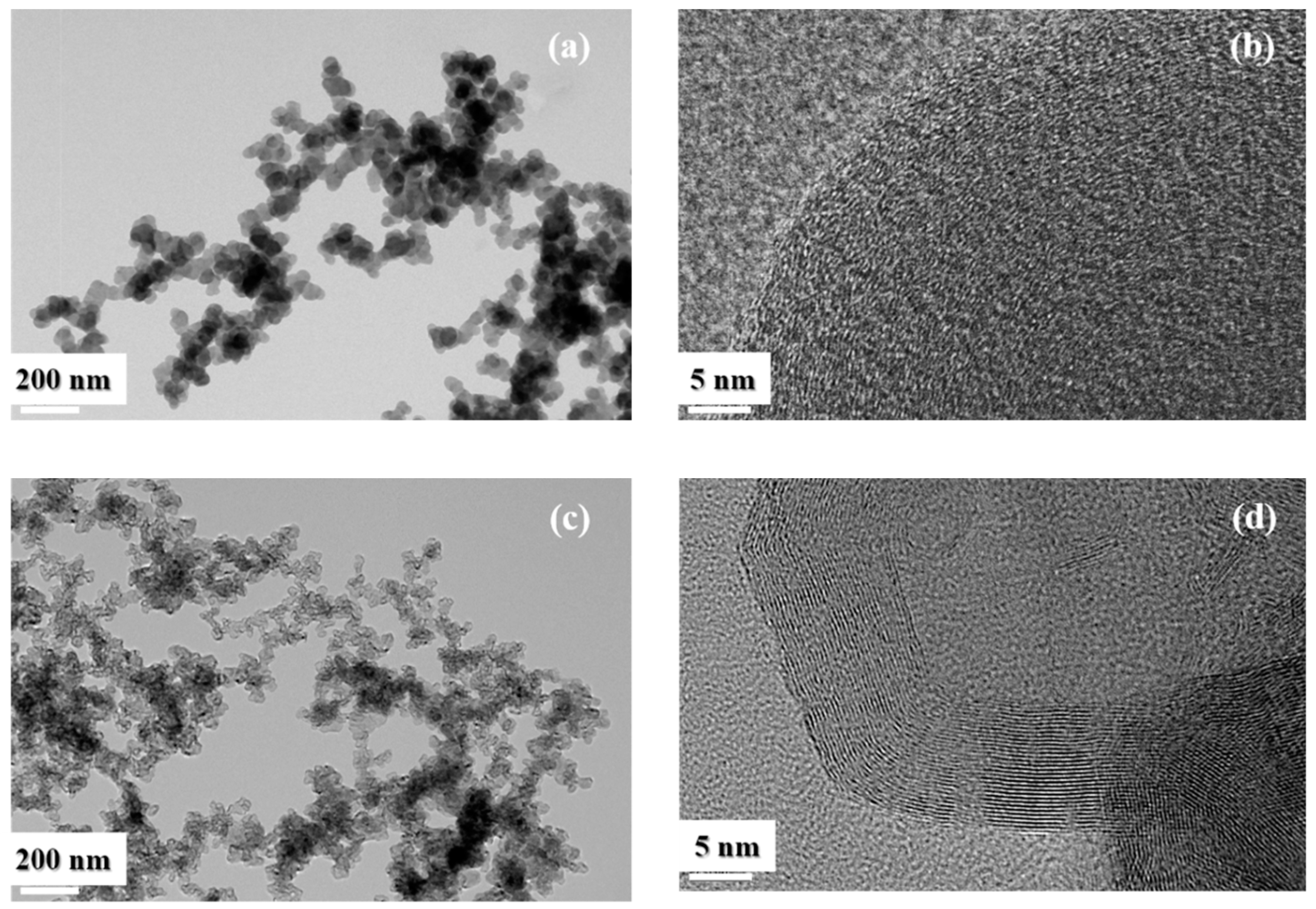
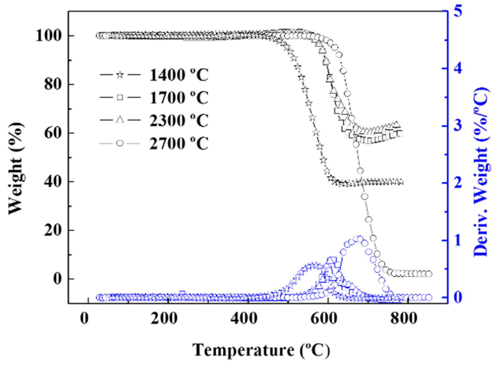
2.3. Soot Characterization
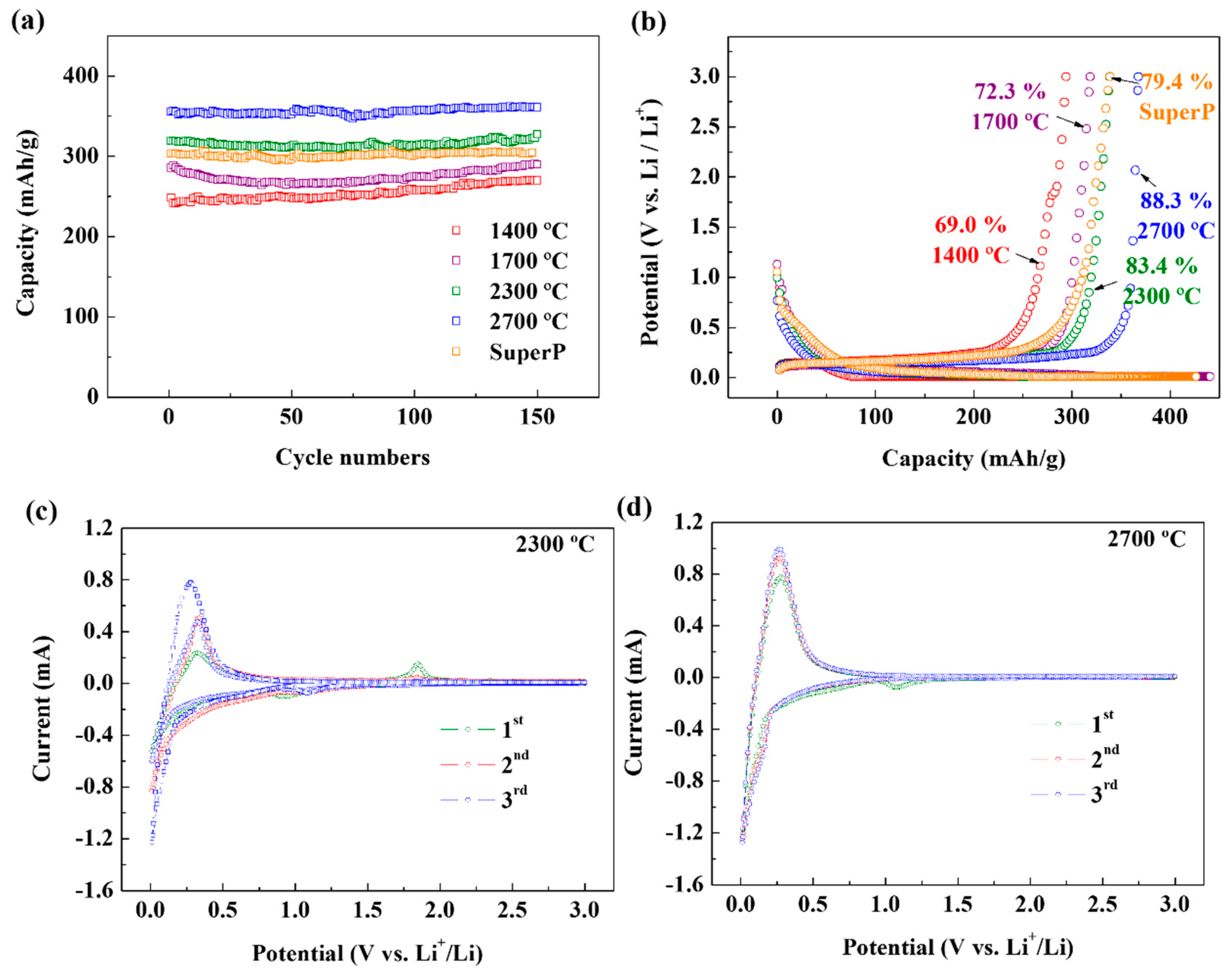
2.4. Electrochemical Measurement
3. Results
4. Conclusions
Supplementary Materials
Author Contributions
Funding
Conflicts of Interest
References
- Lack, D.; Lerner, B.; Granier, C.; Baynard, T.; Lovejoy, E.; Massoli, P.; Ravishankara, A.; Williams, E. Light absorbing carbon emissions from commercial shipping. Geophys. Res. Lett. 2008, 35, L13815. [Google Scholar] [CrossRef]
- Lack, D.; Corbett, J. Black carbon from ships: A review of the effects of ship speed, fuel quality and exhaust gas scrubbing. Atmos. Chem. Phy. 2012, 12, 3985–4000. [Google Scholar] [CrossRef]
- Arctic Climate Impact Assessment (ACIA). Impacts of a Warming Arctic-Arctic Climate Impact Assessment; Cambridge University Press: Cambridge, UK, 2004; ISBN 0521617782. [Google Scholar]
- Solomon, S.; Qin, D.; Manning, M.; Chen, Z.; Marquis, M.; Averyt, K.B.; Tignor, M.; Miller, H.L. Contribution of Working Group I to the Fourth Assessment Report of the Intergovernmental Panel on Climate Change; Cambridge University Press: Cambridge, UK, 2007. [Google Scholar]
- Shindell, D.; Faluvegi, G. Climate response to regional radiative forcing during the twentieth century. Nat. Geosci. 2009, 2, 294. [Google Scholar] [CrossRef]
- Available online: http://docs.imo.org/Shared/Download.aspx?did=69893 (accessed on 7 September 2019).
- Law, K.S.; Stohl, A. Arctic air pollution: Origins and impacts. Science 2007, 315, 1537–1540. [Google Scholar] [CrossRef] [PubMed]
- Flanner, M.G.; Zender, C.S.; Randerson, J.T.; Rasch, P.J. Present day climate forcing and response from black carbon in snow. J. Geophys. Res. 2007, 112, D11202. [Google Scholar] [CrossRef]
- Lindstad, H.E.; Rehn, C.F.; Eskeland, G.S. Sulphur abatement globally in maritime shipping. Transp. Res. Part D Transp. Environ. 2017, 57, 303–313. [Google Scholar] [CrossRef] [Green Version]
- Lindstad, H.; Sandaas, I.; Strømman, A.H. Assessment of cost as a function of abatement options in maritime emission control areas. Transp. Res. Part D Transp. Environ. 2015, 38, 41–48. [Google Scholar] [CrossRef] [Green Version]
- Jiang, L.; Kronbak, J.; Christensen, L.P. The costs and benefits of sulphur reduction measures: Sulphur scrubbers versus marine gas oil. Transp. Res. Part D Transp. Environ. 2014, 28, 19–27. [Google Scholar] [CrossRef]
- Soboleva, T. On the micro-, meso-, and macroporous structures of polymer electrolyte membrane fuel cell catalyst layers. ACS Appl. Mater. Interfaces 2010, 2, 375–384. [Google Scholar] [CrossRef]
- Available online: http://www.carbon-black.org/index.php/carbon-black-uses (accessed on 7 September 2019).
- Harris, R.M. Coloring Technology for Plastics, Plastics Design Library; Society of Plastics Engineers: Norwich, UK, 1999; pp. 227–282. [Google Scholar]
- Koenig, J.L. Spectroscopy of Polymers, 2nd ed.; Elsevier: Amsterdam, The Netherlands, 1999; pp. 397–440. [Google Scholar]
- Parker, G. Encyclopedia of Materials: Science and Technology; Elsevier: Amsterdam, The Netherlands, 2001; pp. 2475–2480. [Google Scholar]
- Ahmad, Z. Principles of Corrosion Engineering and Corrosion Control; Elsevier: Oxford, UK, 2006; pp. 382–437. [Google Scholar]
- Marsh, H.; Reinoso, F.R. Activated Carbon; Elsevier: Oxford, UK, 2006; pp. 13–86. [Google Scholar]
- Tjong, S.C.; Mai, Y.-W. Physical Properties and Applications of Polymer Nanocomposites; Mai, Y.-W., Ed.; Elsevier: Amsterdam, The Netherlands, 2010; pp. 690–722. [Google Scholar]
- Mark, J.E.; Erman, B.; Roland, M. The Science and Technology of Rubber, 4th ed.; Elsevier: Amsterdam, The Netherlands, 2013; pp. 417–471. [Google Scholar]
- Wypych, G. PVC Degradation and Stabilization, 3rd ed.; ChemTec Publishing: Toronto, ON, Canada, 2015; pp. 287–412. [Google Scholar]
- Santos, R.; Loh, W.; Bannwart, A.; Trevisan, O. An overview of heavy oil properties and its recovery and transportation methods. Braz. J. Chem. Eng. 2014, 31, 571–590. [Google Scholar] [CrossRef] [Green Version]
- Ntziachristos, L. Particle emissions characterization from a medium-speed marine diesel engine with two fuels at different sampling conditions. Fuel 2016, 186, 456–465. [Google Scholar] [CrossRef]
- Kasper, A.; Aufdenblatten, S.; Forss, A.; Mohr, M.; Burtscher, H. Particulate emissions from a low-speed marine diesel engine. Aerosol Sci 2007, 41, 24–32. [Google Scholar] [CrossRef]
- Frenklach, M. Reaction mechanism of soot formation in flames. Phys. Chem. Chem. Phys. 2002, 4, 2028–2037. [Google Scholar] [CrossRef]
- Mosbach, S. Towards a detailed soot model for internal combustion engines. Combust. Flame 2009, 156, 1156–1165. [Google Scholar] [CrossRef]
- Sander, M.; Patterson, R.I.; Braumann, A.; Raj, A.; Kraft, M. Developing the PAH-PP soot particle model using process informatics and uncertainty propagation. Proc. Combust. Inst. 2011, 33, 675–683. [Google Scholar] [CrossRef]
- Shukla, B.; Koshi, M. A novel route for PAH growth in HACA based mechanisms. Combust. Flame 2012, 159, 3589–3596. [Google Scholar] [CrossRef]
- Kislov, V.; Sadovnikov, A.; Mebel, A. Formation mechanism of polycyclic aromatic hydrocarbons beyond the second aromatic ring. J. Phys. Chem. A 2013, 117, 4794–4816. [Google Scholar] [CrossRef]
- Tonokura, K. Formation of polycyclic aromatic hydrocarbons and soot particles in combustion. Earozoru Kenkyu 2014, 29, 5–9. [Google Scholar]
- Kroto, H.; McKay, K. The formation of quasi-icosahedral spiral shell carbon particles. Nature 1988, 331, 328. [Google Scholar] [CrossRef]
- Kang, Z.; Wang, Z. Mixed-valent oxide-catalytic carbonization for synthesis of monodispersed nano sized carbon spheres. Philos. Mag. B 1996, 73, 905–929. [Google Scholar] [CrossRef]
- Kang, Z.; Wang, Z. On accretion of nanosize carbon spheres. J. Phys. Chem. 1996, 100, 5163–5165. [Google Scholar] [CrossRef]
- Wang, Z.; Kang, Z. Pairing of pentagonal and heptagonal carbon rings in the growth of nanosize carbon spheres synthesized by a mixed-valent oxide-catalytic carbonization process. J. Phys. Chem. 1996, 100, 17725–17731. [Google Scholar] [CrossRef]


| Items | Description |
|---|---|
| Gross Tonnage | 3981 Mt |
| Length Overall | 107.3 m |
| Breath | 17.2 m |
| Maximum Speed | 16.78 knots |
| Engine Model | MAN B&W 7L35MC |
| Output x RPM (MCR) | 5320 PS × 200 RPM |
| F.O. Consumption (at sea) | HFO: 15.3 MT (at NCR) |
| Kind of Fuel Oil | IFO 380 cSt |
| Equipment | Items | Specification |
|---|---|---|
| 2-stroke diesel engine | Manufacturer | MAN Diesel & Turbo |
| Model | 7L35MC | |
| MCR | 5320 PS × 200 rpm |
| Parameters | Unit | Results |
|---|---|---|
| Specific gravity @15/4 °C | - | 0.9867 |
| Viscosity Kin. @50 °C | mm2/s | 321.3 |
| Flash point | °C | 74 |
| Sulfur content | Weight % | 2.89 |
| Water sediment | Volume % | 0.05 |
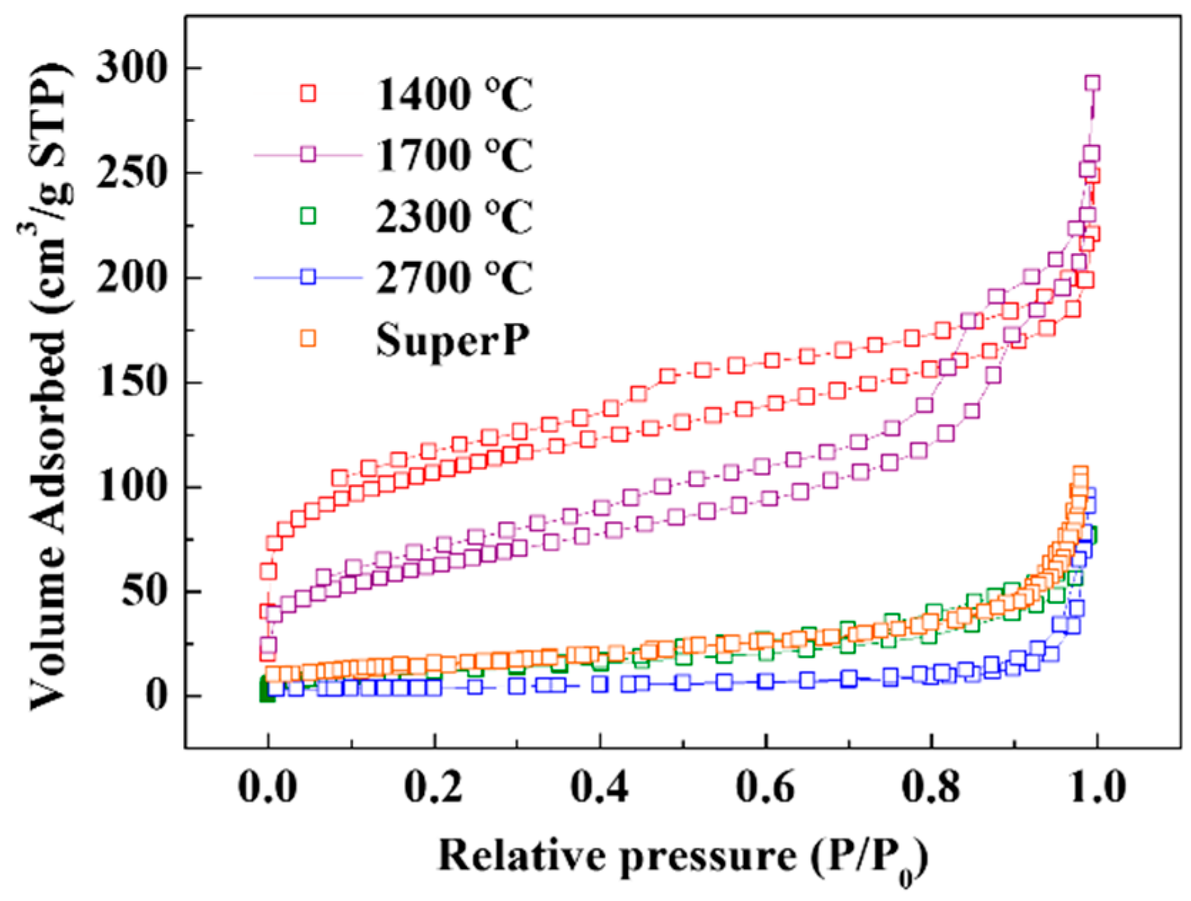
| Sample | BET (m2/g) |
|---|---|
| A: 1400 °C | 376.85 |
| B: 1700 °C | 223.38 |
| C: 2300 °C | 41.87 |
| D: 2700 °C | 13.25 |
| SuperP | 53.28 |
| Sample | Carbon | Hydrogen | Nitrogen | Sulfur |
|---|---|---|---|---|
| A: 1400 °C | 69.49 | 0.01 | Not detected | 29.71 |
| B: 1700 °C | 78.29 | 0.01 | Not detected | 20.79 |
| C: 2300 °C | 87.95 | Not detected | Not detected | 12.04 |
| D: 2700 °C | 98.64 | Not detected | Not detected | Not detected |
| Sample | Initial Decomposition Temperature (°C) | 10% Weight Loss Temperature (°C) | Weight Loss (%) | Residue at 850 °C (%) |
|---|---|---|---|---|
| A: 1400 °C | 544.95 | 556.67 | 59.96 | 40.05 |
| B: 1700 °C | 629.08 | 645.39 | 40.55 | 59.46 |
| C: 2300 °C | 635.35 | 647.19 | 36.79 | 63.20 |
| D: 2700 °C | 632.17 | 632.12 | 97.86 | 2.143 |
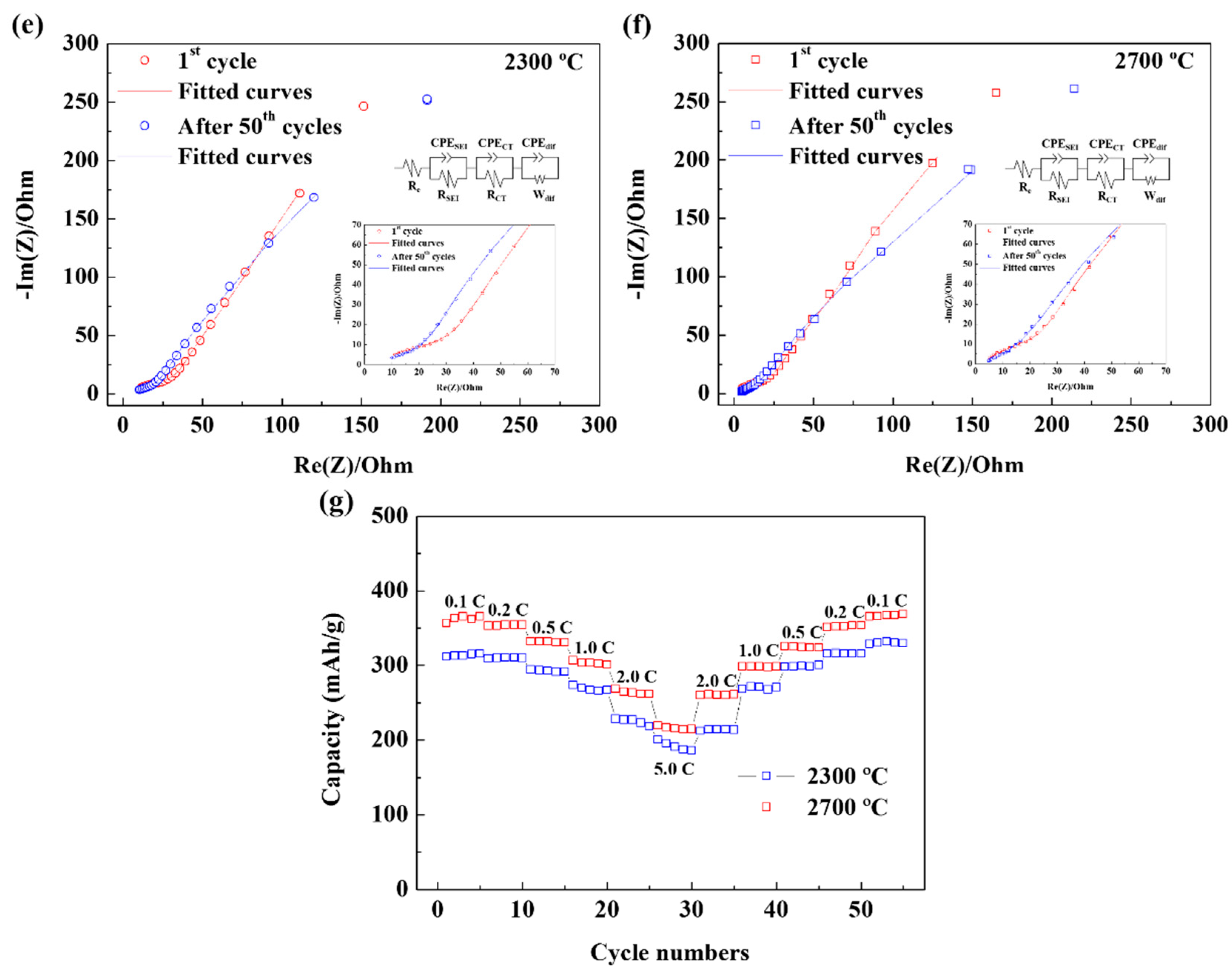
| Re (Ω) | RSEI (Ω) | RCT (Ω) | |
|---|---|---|---|
| 2300 °C | |||
| 1st cycle | 2.213 | 31.43 | 53.72 |
| After 50th cycles | 2.714 | 32.59 | 79.12 |
| 2700 °C | |||
| 1st cycle | 1.849 | 34.6 | 36.07 |
| After 50th cycles | 2.696 | 33.14 | 43.04 |
© 2019 by the authors. Licensee MDPI, Basel, Switzerland. This article is an open access article distributed under the terms and conditions of the Creative Commons Attribution (CC BY) license (http://creativecommons.org/licenses/by/4.0/).
Share and Cite
Choi, J.-H.; Kim, D.-Y.; Lee, W.-J.; Kang, J. Conversion of Black Carbon Emitted from Diesel-Powered Merchant Ships to Novel Conductive Carbon Black as Anodic Material for Lithium Ion Batteries. Nanomaterials 2019, 9, 1280. https://doi.org/10.3390/nano9091280
Choi J-H, Kim D-Y, Lee W-J, Kang J. Conversion of Black Carbon Emitted from Diesel-Powered Merchant Ships to Novel Conductive Carbon Black as Anodic Material for Lithium Ion Batteries. Nanomaterials. 2019; 9(9):1280. https://doi.org/10.3390/nano9091280
Chicago/Turabian StyleChoi, Jae-Hyuk, Dae-Yeong Kim, Won-Ju Lee, and Jun Kang. 2019. "Conversion of Black Carbon Emitted from Diesel-Powered Merchant Ships to Novel Conductive Carbon Black as Anodic Material for Lithium Ion Batteries" Nanomaterials 9, no. 9: 1280. https://doi.org/10.3390/nano9091280
APA StyleChoi, J.-H., Kim, D.-Y., Lee, W.-J., & Kang, J. (2019). Conversion of Black Carbon Emitted from Diesel-Powered Merchant Ships to Novel Conductive Carbon Black as Anodic Material for Lithium Ion Batteries. Nanomaterials, 9(9), 1280. https://doi.org/10.3390/nano9091280