A Tunable Graphene 0–90° Polarization Rotator Achieved by Sine Equation Voltage Adjustment


Abstract
1. Introduction
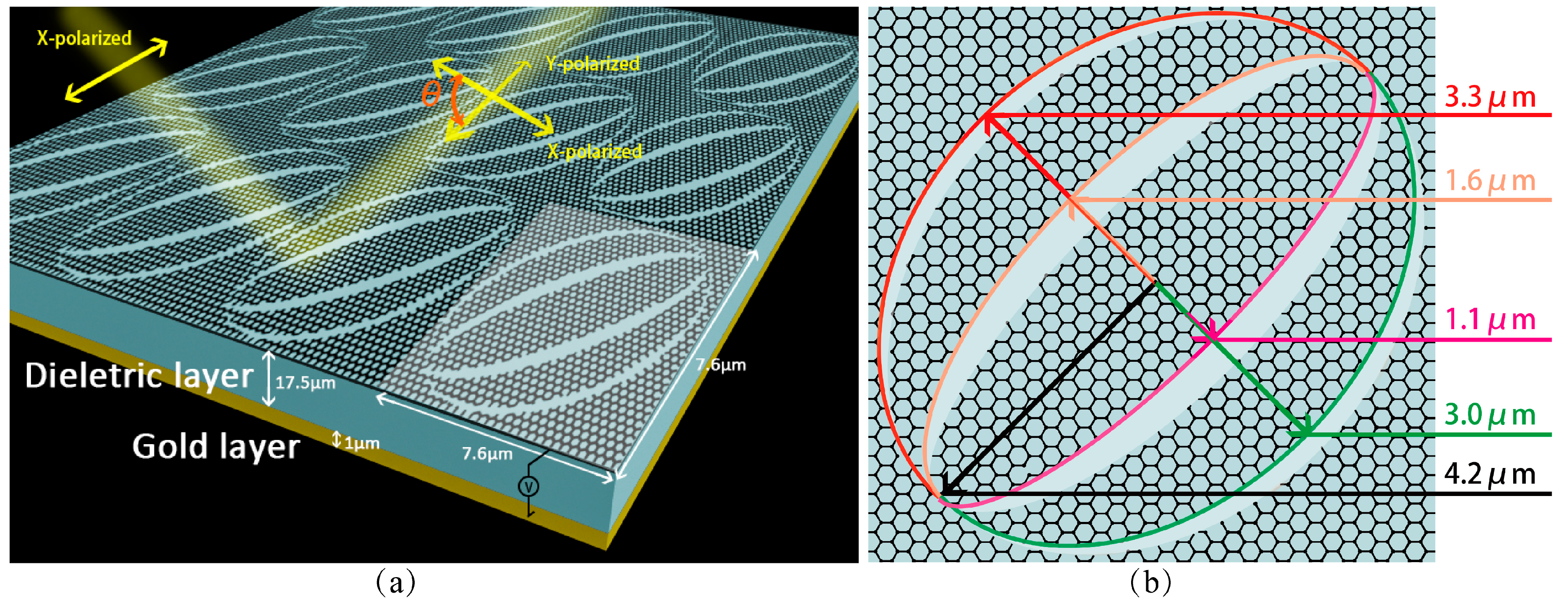
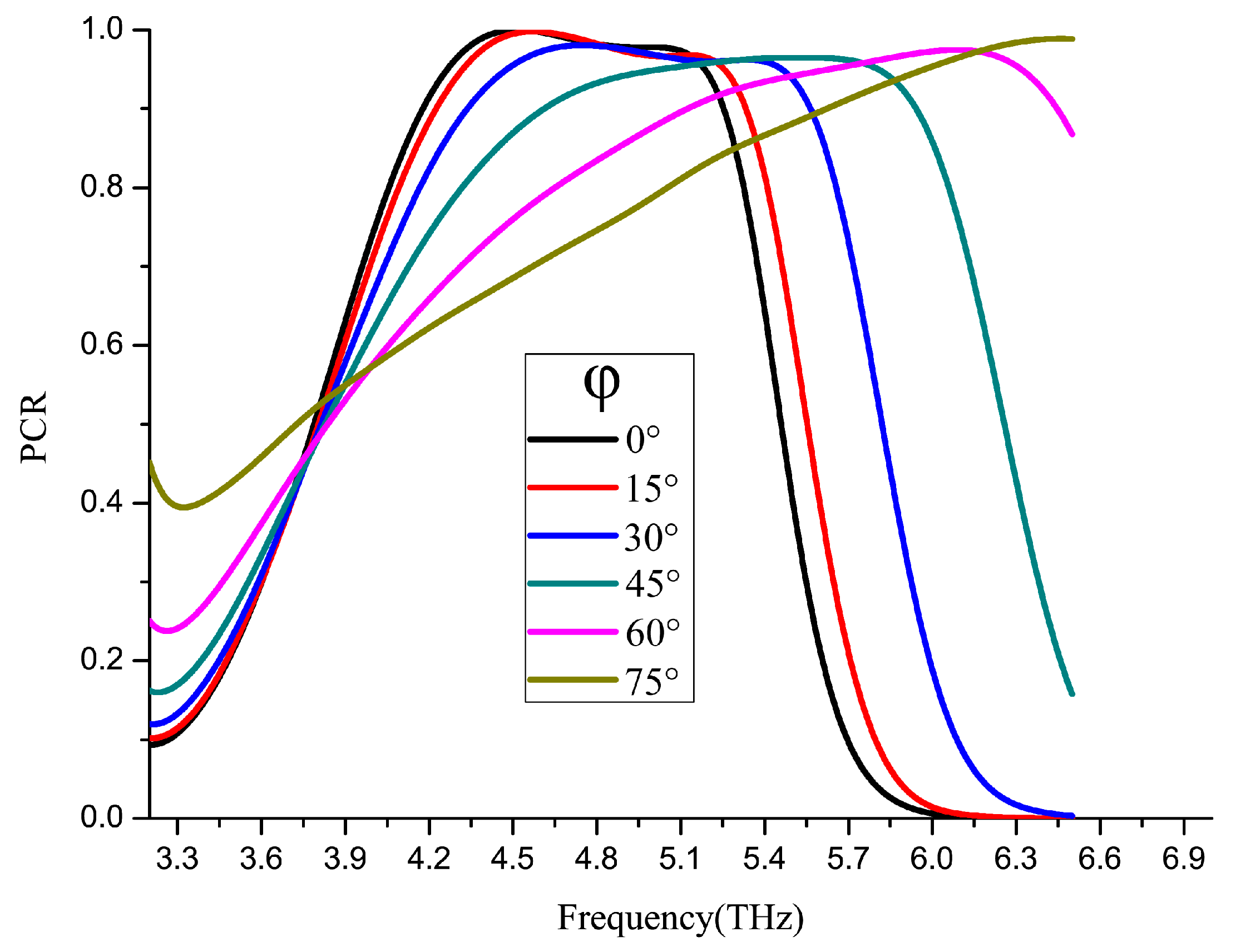
2. The Proposed Structure Design and Simulation Results
3. Discussion on Physical Mechanisms and Theoretical Analyses
4. Radially Polarized Vector Light Devices
5. Discussion
5.1. Fabrication Errors of Dielectric Layer Thickness
5.2. Integration Schemes
6. Conclusions
Author Contributions
Funding
Conflicts of Interest
References
- Alaee, R.; Farhat, M.; Rockstuhl, C.; Lederer, F. A perfect absorber made of a graphene micro-ribbon metamaterial. Opt. Express 2012, 20, 28017–28024. [Google Scholar] [CrossRef] [PubMed]
- Zhang, Q.; Ma, Q.; Yan, S.; Wu, F.; He, X.; Jiang, J. Tunable terahertz absorption in graphene-based metamaterial. Opt. Commun. 2015, 353, 70–75. [Google Scholar] [CrossRef]
- Dmitriev, V.; Monte do Nascimento, C. Planar THz electromagnetic graphene pass-band filter with low polarization and angle of incidence dependencies. Appl. Opt. 2015, 54, 1515–1520. [Google Scholar] [CrossRef]
- Yang, X.; Lu, Y.; Liu, B.; Yao, J. Analysis of Graphene-Based Photonic Crystal Fiber Sensor Using Birefringence and Surface Plasmon Resonance. Plasmonics 2017, 12, 489–496. [Google Scholar] [CrossRef]
- Peng, L.; Li, X.; Jiang, X.; Li, S. A Novel THz Half-Wave Polarization Converter for Cross-Polarization Conversions of Both Linear and Circular Polarizations and Polarization Conversion Ratio Regulating by Graphene. J. Lightwave Technol. 2018, 36, 4250–4258. [Google Scholar] [CrossRef]
- Meissner, T.; Wentz, F.J. Polarization rotation and the third Stokes parameter: The effects of spacecraft attitude and Faraday rotation. IEEE Trans. Geosci. Remote Sens. 2006, 44, 506–515. [Google Scholar] [CrossRef]
- Wu, L.; Yang, Z.; Cheng, Y.; Gong, R.; Zhao, M.; Zheng, Y.; Duan, J.A.; Yuan, X. Circular polarization converters based on bi-layered asymmetrical split ring metamaterials. Appl. Phys. A 2014, 116, 643–648. [Google Scholar] [CrossRef]
- Gao, X.; Han, X.; Cao, W.; Li, H.O.; Ma, H.F.; Cui, T.J. Ultrawideband and High-Efficiency Linear Polarization Converter Based on Double V-Shaped Metasurface. IEEE Trans. Antennas Propag. 2015, 63, 3522–3530. [Google Scholar] [CrossRef]
- Geim, A.K.; Novoselov, K.S. The rise of graphene. Nat. Mater. 2007, 6, 183. [Google Scholar] [CrossRef]
- Geim, A.K. Graphene: Status and prospects. Science 2009, 324, 1530–1534. [Google Scholar] [CrossRef] [PubMed]
- Zhu, J.; Li, S.; Deng, L.; Zhang, C.; Yang, Y.; Zhu, H. Broadband tunable terahertz polarization converter based on a sinusoidally-slotted graphene metamaterial. Opt. Mater. Express 2018, 8, 1164–1173. [Google Scholar] [CrossRef]
- Xu, J.; Li, R.; Qin, J.; Wang, S.; Han, T. Ultra-broadband wide-angle linear polarization converter based on H-shaped metasurface. Opt. Express 2018, 26, 20913–20919. [Google Scholar] [CrossRef] [PubMed]
- Yang, C.; Luo, Y.; Guo, J.; Pu, Y.; He, D.; Jiang, Y.; Xu, J.; Liu, Z. Wideband tunable mid-infrared cross polarization converter using rectangle-shape perforated graphene. Opt. Express 2016, 24, 16913–16922. [Google Scholar] [CrossRef]
- Chen, M.; Chang, L.; Gao, X.; Chen, H.; Wang, C.; Xiao, X.; Zhao, D. Wideband tunable cross polarization converter based on a graphene metasurface with a hollow-carved “H” array. IEEE Photonics J. 2017, 9, 1–12. [Google Scholar] [CrossRef]
- Hua, C.; Chen, S.; Ping, Y.; Li, J.; Xie, B.; Li, Z.; Tian, J. Dynamically tunable broadband mid-infrared cross polarization converter based on graphene metamaterial. Appl. Phys. Lett. 2013, 103, 151107. [Google Scholar]
- Fan, R.-H.; Liu, D.; Peng, R.-W.; Shi, W.-B.; Jing, H.; Huang, X.-R.; Wang, M. Broadband integrated polarization rotator using three-layer metallic grating structures. Opt. Express 2018, 26, 516–524. [Google Scholar] [CrossRef] [PubMed]
- Yin, Z.; Feng, Y.; Tian, J.; Jie, C.; Zhao, J.; Bo, Z. Tunable broadband polarization rotator in terahertz frequency based on graphene metamaterial. Carbon 2018, 133, 170–175. [Google Scholar]
- Nieminen, T.A.; Heckenberg, N.R.; Rubinsztein-Dunlop, H. Forces in optical tweezers with radially and azimuthally polarized trapping beams. Opt. Lett. 2008, 33, 122–124. [Google Scholar] [CrossRef]
- Lei, B.; Cheng, X.; Gao, C.; Shi, J.; Zhong, H. Dynamic Polarization Direction Monitoring in Optical Fibers Based on Radially Polarized Light. In Proceedings of the Advanced Photonics 2018 (BGPP, IPR, NP, NOMA, Sensors, Networks, SPPCom, SOF), Zurich, Switzerland, 2 July 2018; p. SeW3E.8. [Google Scholar]
- Yoshiki, K.; Ryosuke, K.; Hashimoto, M.; Hashimoto, N.; Araki, T. Second-harmonic-generation microscope using eight-segment polarization-mode converter to observe three-dimensional molecular orientation. Opt. Lett. 2007, 32, 1680–1682. [Google Scholar] [CrossRef] [PubMed]
- Yu, A.-P.; Chen, G.; Zhang, Z.-H.; Wen, Z.-Q.; Dai, L.-R.; Zhang, K.; Jiang, S.-L.; Wu, Z.-X.; Li, Y.-Y.; Wang, C.-T.; et al. Creation of Sub-diffraction Longitudinally Polarized Spot by Focusing Radially Polarized Light with Binary Phase Lens. Sci. Rep. 2016, 6, 38859. [Google Scholar] [CrossRef]
- Stalder, M.; Schadt, M. Linearly polarized light with axial symmetry generated by liquid-crystal polarization converters. Opt. Lett. 1996, 21, 1948–1950. [Google Scholar] [CrossRef] [PubMed]
- Zhang, Y.-Q.; Zeng, X.-Y.; Zhang, R.-R.; Zhan, Z.-J.; Li, X.; Ma, L.; Liu, C.-X.; He, C.-W.; Cheng, C.-F. Generation of a plasmonic radially polarized vector beam with linearly polarized illumination. Opt. Lett. 2018, 43, 4208. [Google Scholar] [CrossRef]
- Swanson, E.S. Modeling DNA response to terahertz radiation. Phys. Rev. E Stat. Nonlinear Soft Matter Phys. 2011, 83, 040901. [Google Scholar] [CrossRef] [PubMed]
- Gallot, G.; Grischkowsky, D. Electro-optic detection of terahertz radiation. J. Opt. Soc. Am. B 1999, 16, 1204–1212. [Google Scholar] [CrossRef]
- Banerjee, D.; von Spiegel, W.; Thomson, M.D.; Schabel, S.; Roskos, H.G. Diagnosing water content in paper by terahertz radiation. Opt. Express 2008, 16, 9060–9066. [Google Scholar] [CrossRef] [PubMed]
- Hanson, G.W. Dyadic Green’s Functions and Guided Surface Waves for a Surface Conductivity Model of Graphene. J. Appl. Phys. 2007, 103, 19912. [Google Scholar] [CrossRef]
- Xiao, S.; Zhu, X.; Li, B.-H.; Mortensen, N.A. Graphene-plasmon polaritons: From fundamental properties to potential applications. Front. Phys. 2016, 11, 117801. [Google Scholar] [CrossRef]


© 2019 by the authors. Licensee MDPI, Basel, Switzerland. This article is an open access article distributed under the terms and conditions of the Creative Commons Attribution (CC BY) license (http://creativecommons.org/licenses/by/4.0/).
Share and Cite
Dai, J.; Wei, Z.; Zhao, L.; Lin, Q.; Lou, Y. A Tunable Graphene 0–90° Polarization Rotator Achieved by Sine Equation Voltage Adjustment. Nanomaterials 2019, 9, 849. https://doi.org/10.3390/nano9060849
Dai J, Wei Z, Zhao L, Lin Q, Lou Y. A Tunable Graphene 0–90° Polarization Rotator Achieved by Sine Equation Voltage Adjustment. Nanomaterials. 2019; 9(6):849. https://doi.org/10.3390/nano9060849
Chicago/Turabian StyleDai, Jinsong, Zhongchao Wei, Lin Zhao, Qiyuan Lin, and Yuyao Lou. 2019. "A Tunable Graphene 0–90° Polarization Rotator Achieved by Sine Equation Voltage Adjustment" Nanomaterials 9, no. 6: 849. https://doi.org/10.3390/nano9060849
APA StyleDai, J., Wei, Z., Zhao, L., Lin, Q., & Lou, Y. (2019). A Tunable Graphene 0–90° Polarization Rotator Achieved by Sine Equation Voltage Adjustment. Nanomaterials, 9(6), 849. https://doi.org/10.3390/nano9060849