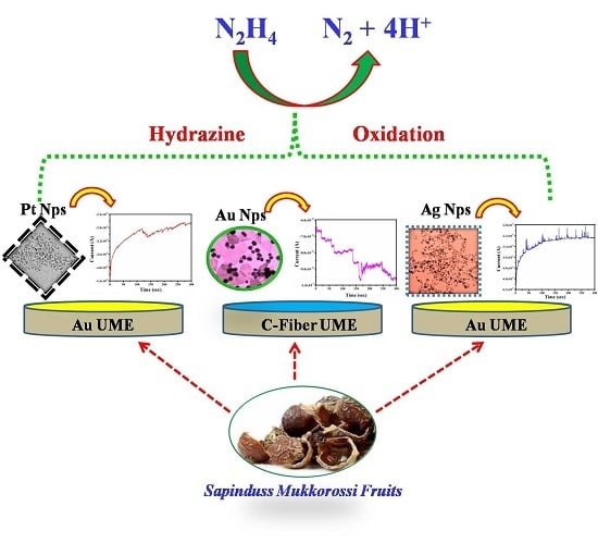
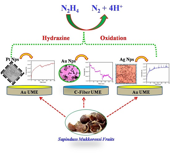
Observation of Single Nanoparticle Collisions with Green Synthesized Pt, Au, and Ag Nanoparticles Using Electrocatalytic Signal Amplification Method


Abstract
:
1. Introduction
2. Materials and Methods
2.1. Reagent
2.2. Preparation of Sapinduss Mukkorossi Fruit Extract (SMFE)
2.3. Preparation of NPs and Characterization
2.4. Preparation of UME
2.5. Electrochemical Cell
3. Results & Discussion
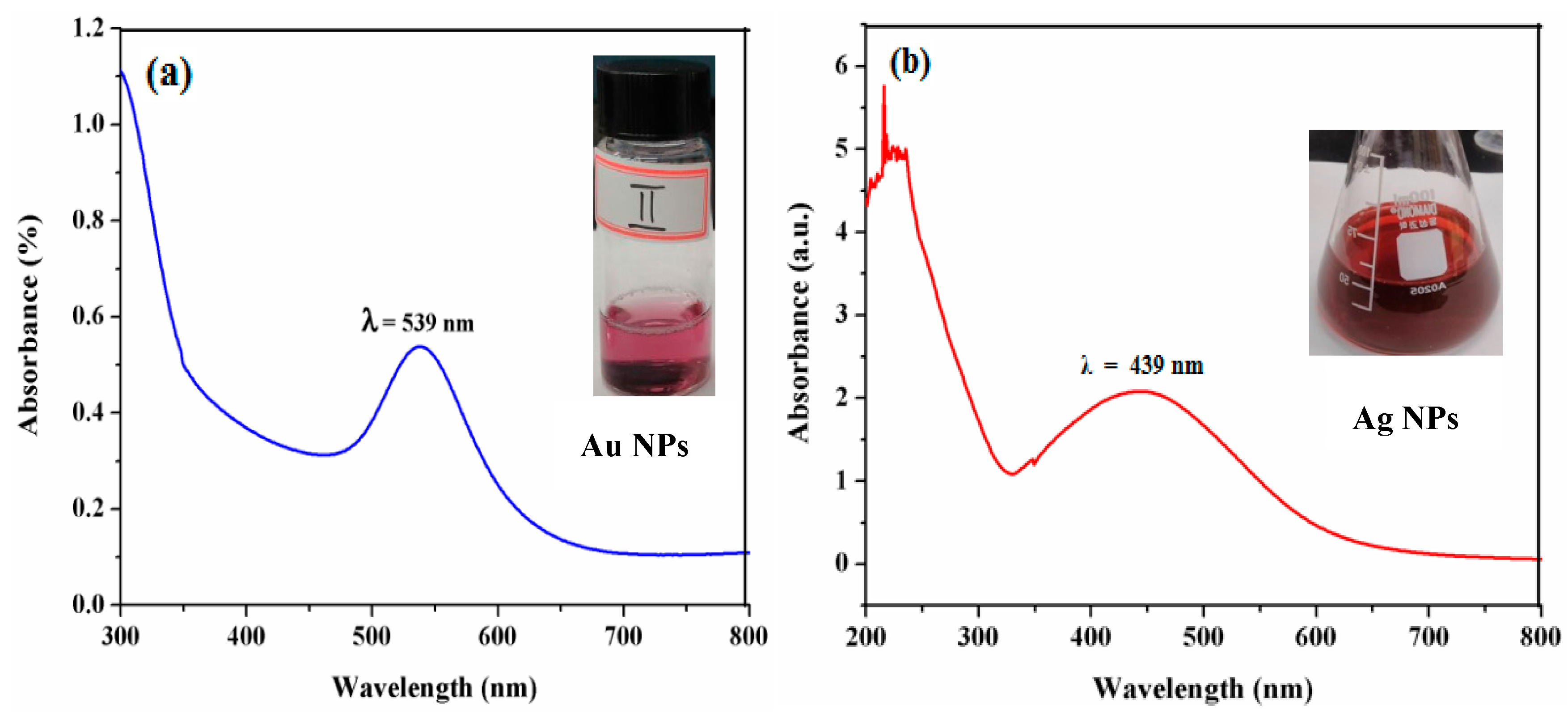
3.1. UV-Visible Spectroscopic Measurements
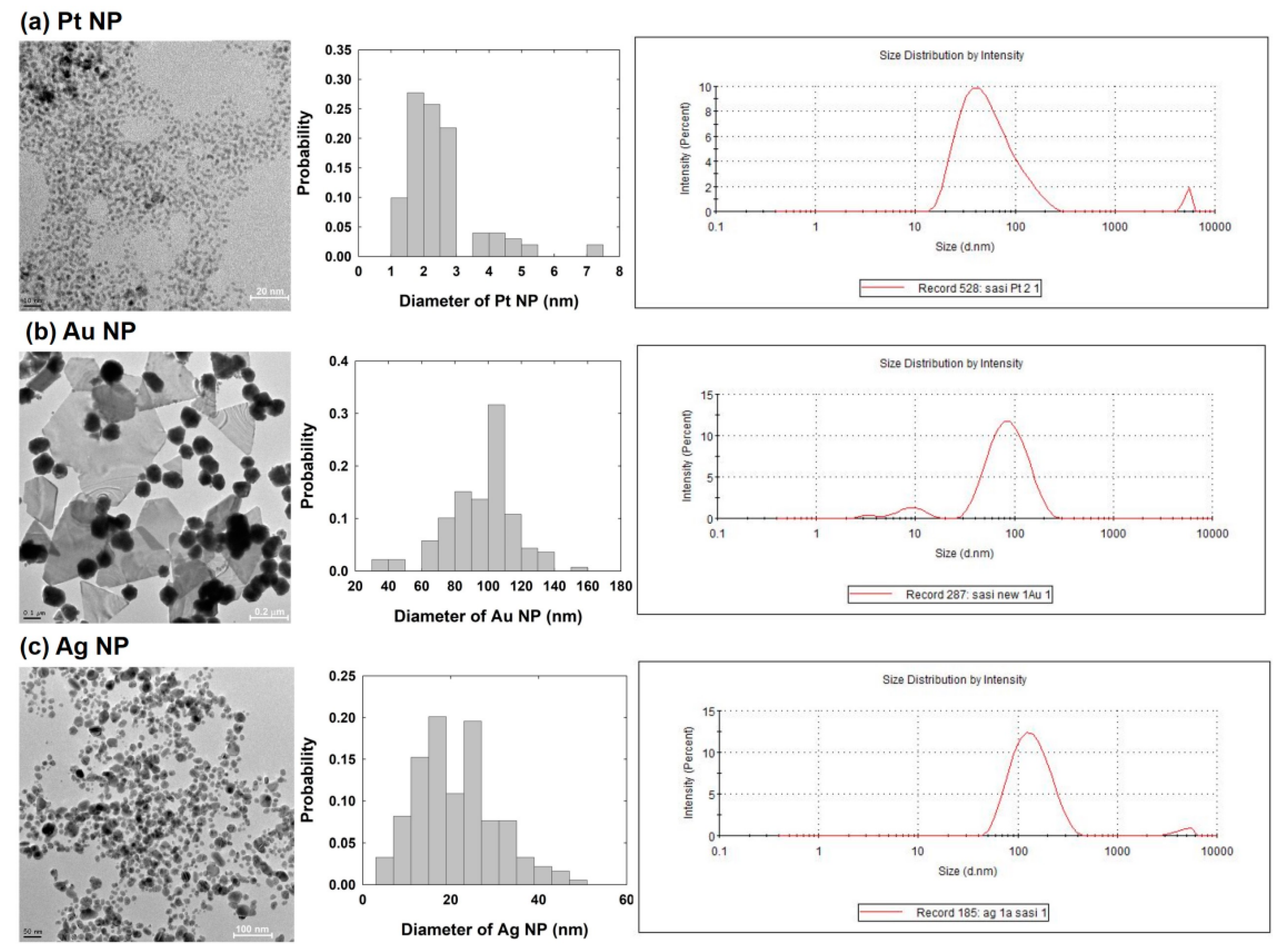
3.2. Dynamic Light Scattering (DLS) and Transmission Electron Microscope (TEM) Measurements
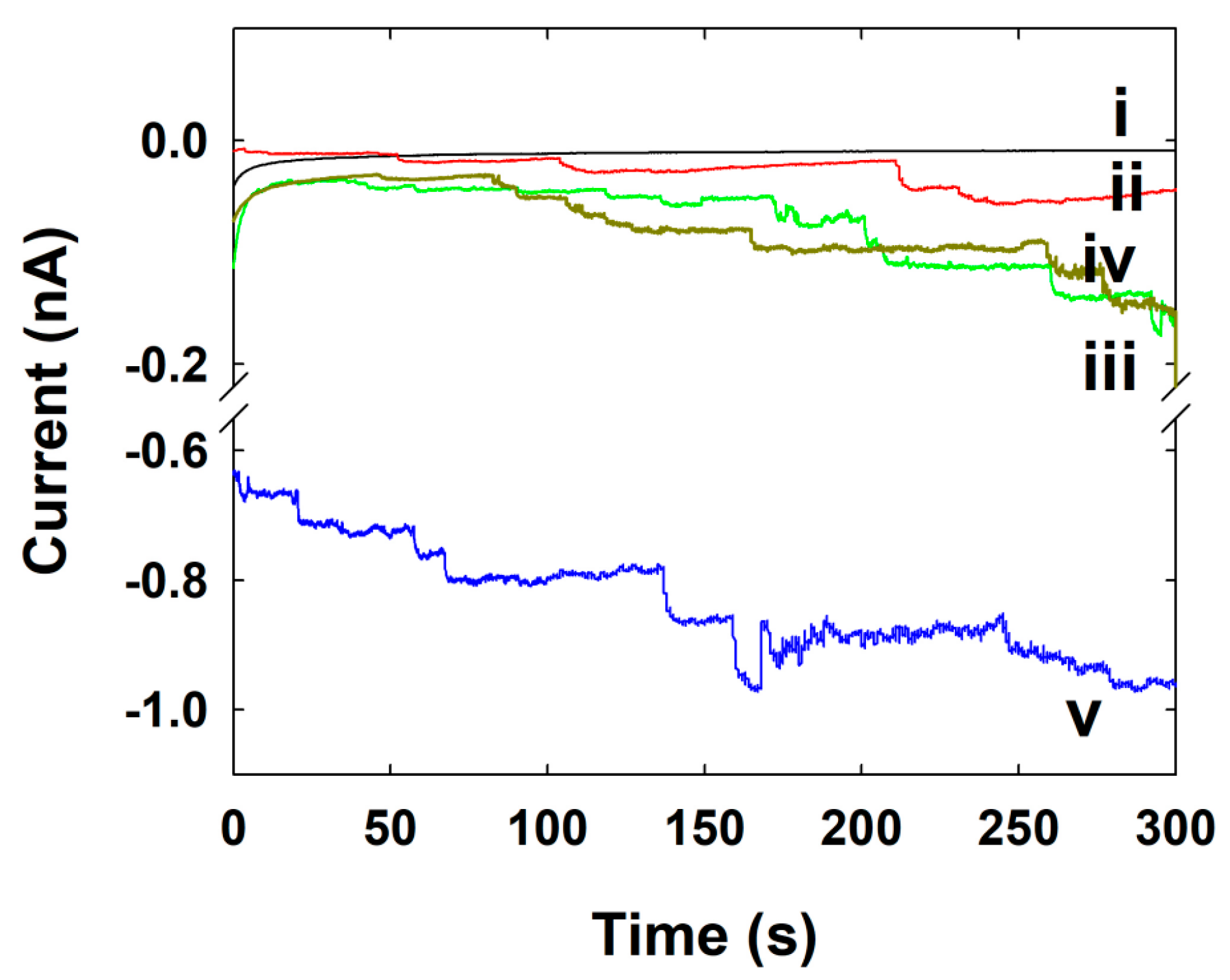
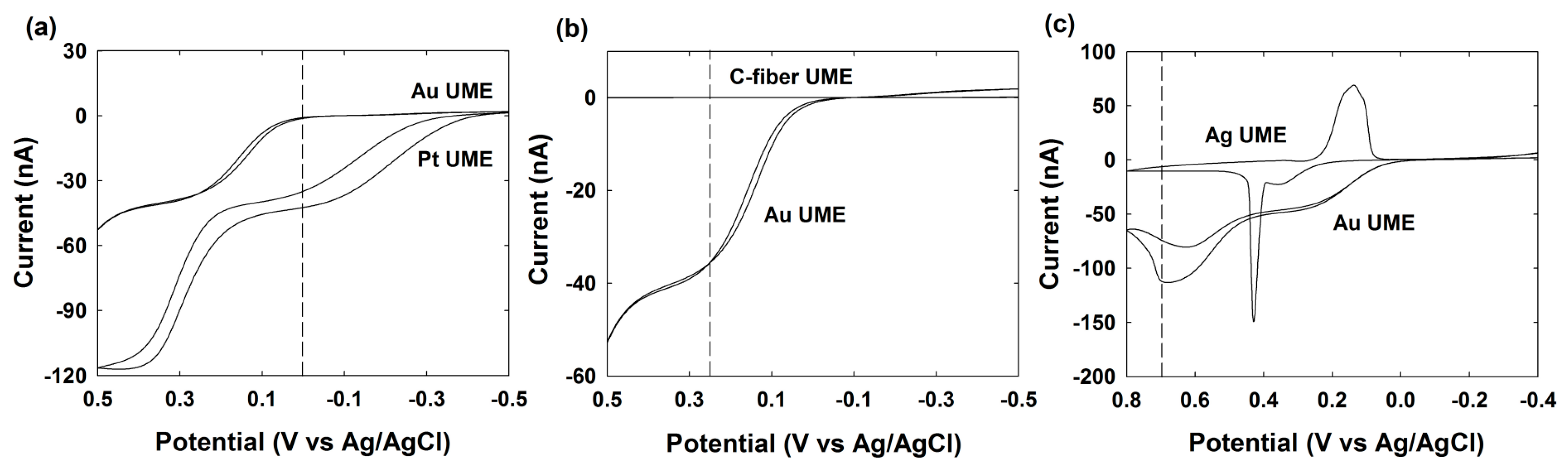
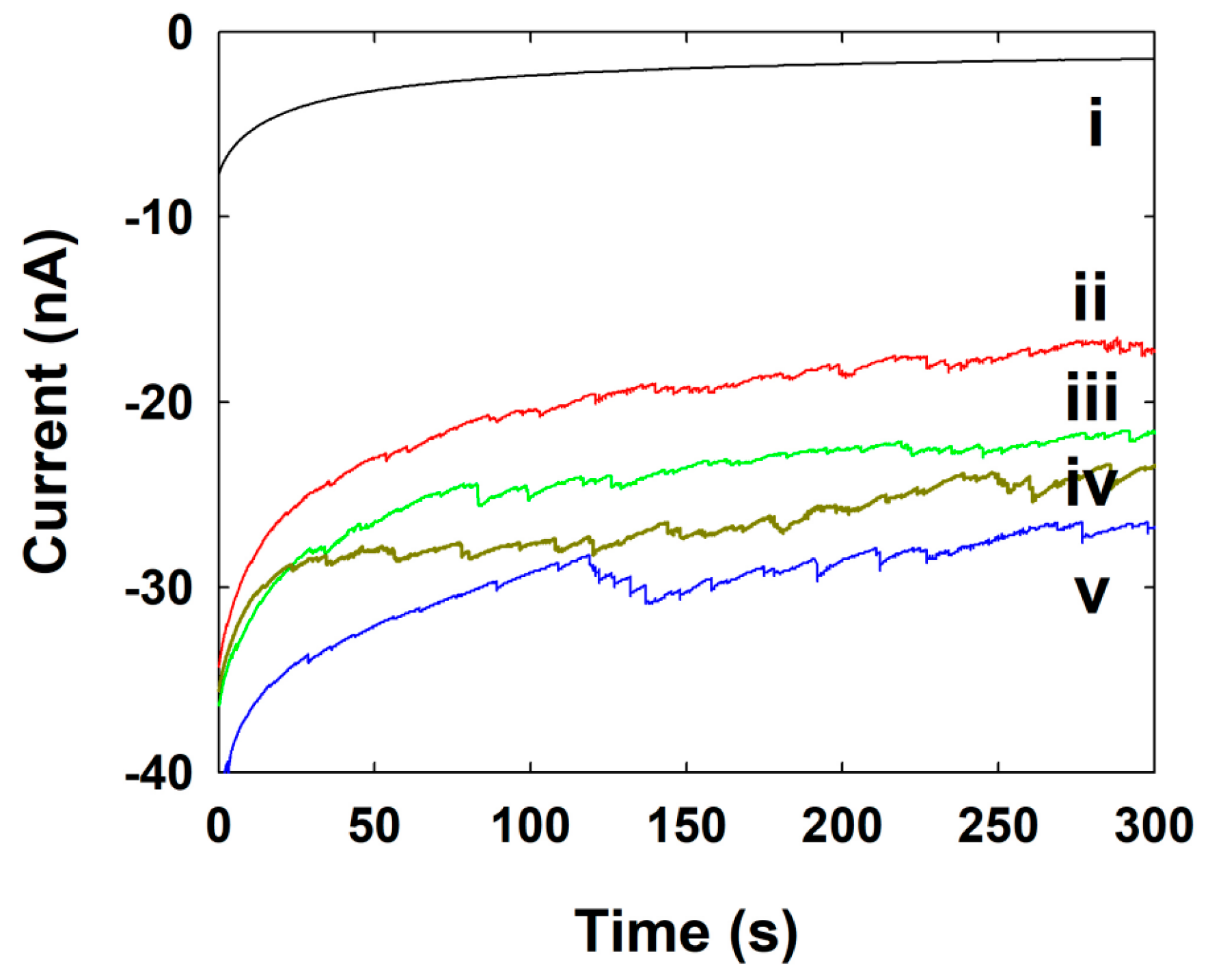
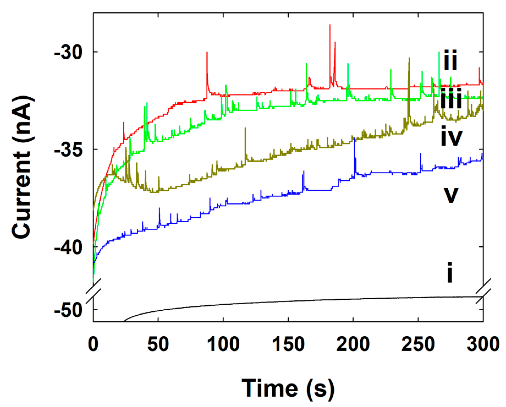
3.3. Single NP Collision Experiment
3.4. Pt NPs Collision Signal on Au UME
3.5. Au NPs Collision Signal on C-Fiber UME
3.6. Ag NPs Collision Signal on Au UME
4. Conclusions
Author Contributions
Funding
Conflicts of Interest
References
- Mohanpuria, P.; Rana, N.K.; Yadav, S.K. Biosynthesis of nanoparticles: Technological concepts and future applications. J. Nanopart. Res. 2008, 10, 507–517. [Google Scholar] [CrossRef]
- Shankar, S.S.; Rai, A.; Ankamwar, B.; Singh, A.; Ahmad, A.; Sastry, M. Biological synthesis of triangular gold nanoprisms. Nat. Mater. 2004, 3, 482–488. [Google Scholar] [CrossRef]
- Vilchis-Nestor, A.R.; Sanchez-Mendieta, V.; Camacho-Lopez, M.A.; Camacho-Lopez, M.A.; Arenas-Alatorre, J.A. Solventless synthesis and optical properties of Au and Ag nanoparticles using Camellia sinensis extract. Mater. Lett. 2008, 62, 3103–3105. [Google Scholar] [CrossRef]
- Li, S.; Shen, Y.; Xie, A.; Yu, X.; Qui, L.; Zhang, L.; Zhang, Q. Green synthesis of silver nanoparticles using Capsicum annuum L. Extract. Green Chem. 2007, 9, 852–858. [Google Scholar] [CrossRef]
- Huang, J.; Li, Q.; Sun, D.; Lu, Y.; Su, Y.; Yang, X.; Wang, H.; Wang, Y.; Shao, W.; He, N.; et al. Biosynthesis of Silver and Gold Nanoparticles by Novel Sundried Cinnamomum camphora Leaves. Nanotechnology 2007, 18, 105104–105115. [Google Scholar] [CrossRef]
- Shankar, S.; Ahmad, A.; Sastry, M. Geranium leaf assisted biosynthesis of silver nanoparticles. Biotechnol. Prog. 2003, 19, 1627–1631. [Google Scholar] [CrossRef] [PubMed]
- Cheng, W.; Compton, R.G. Electrochemical detection of nanoparticles by ‘nano-impact’ methods. TrAC-Trends Anal. Chem. 2014, 58, 79–89. [Google Scholar] [CrossRef]
- Zhou, Y.-G.; Rees, N.V.; Compton, R.G. The electrochemical detection and characterization of silver nanoparticles in aqueous solution. Angew. Chem. Int. Ed. 2011, 50, 4219–4221. [Google Scholar] [CrossRef] [PubMed]
- Zhou, H.; Fan, F.-R.F.; Bard, A.J. Observation of Discrete Au Nanoparticle Collisions by Electrocatalytic Amplification Using Pt Ultramicroelectrode Surface Modification. J. Phys. Chem. Lett. 2010, 1, 2671–2674. [Google Scholar] [CrossRef]
- Yakushenko, A.; Mayer, D.; Buitenhuis, J.; Offenhaeusser, A.; Wolfrum, B. Electrochemical artifacts originating from nanoparticle contamination by Ag/AgCl quasi-reference electrodes. Lab Chip 2014, 14, 602–607. [Google Scholar] [CrossRef]
- Stuart, E.J.E.; Tschulik, K.; Batchelor-McAuley, C.; Compton, R.G. Electrochemical Observation of Single Collision Events: Fullerene Nanoparticles. ACS Nano 2014, 8, 7648–7654. [Google Scholar] [CrossRef] [PubMed]
- Xiao, X.; Bard, A.J. Observing single nanoparticle collisions at an ultramicroelectrode by electrocatalytic amplification. J. Am. Chem. Soc. 2007, 129, 9610–9612. [Google Scholar] [CrossRef] [PubMed]
- Shin, C.; Park, T.E.; Park, C.; Kwon, S.J. Observation of Single Pt Nanoparticle Collisions: Enhanced Electrocatalytic Activity on a Pd Ultramicroelectrode. ChemPhysChem 2016, 17, 1637–1641. [Google Scholar] [CrossRef] [PubMed]
- Xiao, X.; Fan, F.-R.F.; Zhou, J.; Bard, A.J. Current transient in single nanoparticle collision events. J. Am. Chem. Soc. 2008, 130, 16669–16677. [Google Scholar] [CrossRef] [PubMed]
- Bard, A.J.; Zhou, H.; Kwon, S.J. Electrochemistry of Single Nanoparticles via Electrocatalytic Amplification. Isr. J. Chem. 2010, 50, 267–276. [Google Scholar] [CrossRef]
- Kahk, J.M.; Ress, N.V.; Pillay, J.; Tsshikhudo, R.; Vilakazi, S.; Compton, R.G. Electron transfer kinetics at single nanoparticles. Nano Today 2012, 7, 174–179. [Google Scholar] [CrossRef]
- Peter, A.D.; Bo, Z. Temporally-Resolved Ultrafast Hydrogen Adsorption and Evolution on Single Platinum Nanoparticles. Anal. Chem. 2019, 91, 64023–64030. [Google Scholar]
- Xiang, Z.P.; Deng, H.Q.; Peljo, P.; Fu, Z.Y.; Wang, S.L.; Mandler, D.; Sun, G.Q.; Liang, Z.X. Electrochemical Dyanamics of a Single Platinum Nanoparticle Collision Event for the Hydrogen Evolution Reaction. Angew. Chem. Int. Ed. 2018, 57, 3464–3468. [Google Scholar] [CrossRef]
- Kwon, S.J.; Fan, F.-R.F.; Bard, A.J. Observing Iridium Oxide (IrOx) Single Nanoparticle Collisions at Ultramicroelectrodes. J. Am. Chem. Soc. 2010, 132, 13165–13167. [Google Scholar] [CrossRef]
- Choi, Y.D.; Jung, S.Y.; Kim, K.J.; Kwon, S.J. Combined Blip and Staircase Response of Ascorbic Acid-Stabilized Copper Single Nanoparticle Collision by Electrocatalytic Glucose Oxidation. Chem. Asian J. 2016, 11, 1338–1342. [Google Scholar] [CrossRef]
- Xiao, X.; Pan, S.; Jang, J.S.; Fan, F.-R.F.; Bard, A.J. Single Nanoparticle Electrocatalysis: Effect of Monolayers on Particle and Electrode on Electron Transfer. J. Phys. Chem. C 2009, 113, 14978–14982. [Google Scholar] [CrossRef]
- Robinson, D.A.; Kondajji, A.M.; Castaneda, A.D.; Dasari, R.; Crooks, R.M.; Stevenson, K.J. Addressing Colloidal Stability for Unambiguous Electroanalysis of Single Nanoparticle Impacts. J. Phys. Chem. Lett. 2016, 7, 2512–2517. [Google Scholar] [CrossRef] [PubMed]
- Guo, Z.-H.; Percival, S.J.; Zhang, B. Chemically resolved transient collision events of single electrocatalytic nanoparticles. J. Am. Chem. Soc. 2014, 136, 8879–8882. [Google Scholar] [CrossRef] [PubMed]
- Zhou, H.; Park, J.H.; Fan, F.-R.F.; Bard, A.J. Observation of single metal nanoparticle collisions by open circuit (mixed) potential changes at an ultramircoelectrode. J. Am. Chem. Soc. 2012, 134, 13212–13215. [Google Scholar] [CrossRef] [PubMed]
- Kwon, S.J.; Zhou, H.; Fan, F.-R.F.; Vorobyev, V.; Zhang, B.; Bard, A.J. Stochastic electrochemistry with electrocatalytic nanoparticles at inert ultramicroelectrodes—Theory and experiments. Phys. Chem. Chem. Phys. 2011, 13, 5394–5402. [Google Scholar] [CrossRef] [PubMed]
- Kim, D.Y.; Lee, S.; Kwon, S.J. Detection of Single Au Nanoparticle Collisions Using Electrocatalytic Amplification Method. Bull. Korean Chem. Soc. 2015, 36, 678–681. [Google Scholar]
- Castanneda, A.D.; Alligrant, T.M.; Loussaert, J.A.; Crooks, R.M. Electrocatalytic Amplification of Nanoparticle Collisions at Electrodes Modified with Polyelectrolyte Multilayer Films. Langmuir 2015, 31, 876–885. [Google Scholar] [CrossRef]
- Kleijn, S.E.F.; Bou, B.S.; Yanson, A.I.; Koper, M.T.M. Influence of Hydrazine-Induced Aggregation on the Electrochemical Detection of Platinum Nanoparticles. Langmuir 2013, 29, 2054–2064. [Google Scholar] [CrossRef]
- Piraman, S.; Sundar, S.; Mariappan, R.; Kim, Y.Y.; Min, K. Nanospheres and nanoleaves of γ-Fe2O3 architecturing for magnetic and biomolecule sensing applications. Sens. Actuator B Chem. 2016, 234, 386–394. [Google Scholar] [CrossRef]
- Sundar, S.; Venkatachalam, G.; Kwon, S.J. Biosynthesis of Copper Oxide (CuO) Nanowires and Their Use for the Electrochemical Sensing of Dopamine. Nanomaterials 2018, 8, 823. [Google Scholar] [CrossRef]
- Lee, S.Y.; Krishnamurthy, S.; Cho, C.W.; Yun, Y.S. Biosynthesis of Gold Nanoparticles Using Ocimum sanctum Extracts by Solvents with Different Polarity. ACS Sustain. Chem. Eng. 2016, 4, 2651–2659. [Google Scholar] [CrossRef]
- Rashid, Z.; Moadi, T.; Ghahremanzadeh, R. Green synthesis and characterization of silver nanoparticles using Ferula latisecta leaf extract and their application as a catalyst for the safe and simple one-pot preparation of spirooxindoles in water. New J. Chem. 2016, 40, 3343–3349. [Google Scholar] [CrossRef]
- Shujahadeen, B.A.; Omed, G.A.; Dlear, R.S.; Mariwan, A.R.; Hameed, M.A. Investigation of Metallic Silver Nanoparticles through UV-Vis and Optical Micrograph Techniques. Int. J. Electrochem. Sci. 2017, 12, 363–373. [Google Scholar]
- Mun, S.K.; Lee, S.; Kim, D.Y.; Kwon, S.J. Various Current Responses of Single Silver Nanoparticle Collisions on a Gold Ultramicroelectrode Depending on the Collision Conditions. Chem. Asian J. 2017, 12, 2434–2440. [Google Scholar] [CrossRef] [PubMed]
- Cesar, A.; Ledon, O.; Zoski, C.G. Pt Nanoparticle Collisions Detected by Electrocatalytic Amplification and Atomic Force Microscopy Imaging: Nanoparticle Collision Frequency, Adsorption, and Random Distribution at an Ultramicroelectrode Surface. Anal. Chem. 2017, 89, 6424–6431. [Google Scholar]
- Jung, A.R.; Lee, S.; Joo, J.W.; Shin, C.; Bae, H.; Moon, S.G.; Kwon, S.J. Potential-controlled current responses from staircase to blip in single Pt nanoparticle collisions on a Ni ultramicroelectrode. J. Am. Chem. Soc. 2015, 137, 1762–1765. [Google Scholar] [CrossRef] [PubMed]
- Mirkin, M.V.; Amemiya, S. Nanoelectrochemistry, 1st ed.; CRC Press: New York, NY, USA, 2015; Chapter 8; pp. 241–291. [Google Scholar]
- Yoo, J.J.; Kim, J.; Crooks, R.M. Direct electrochemical detection of individual collisions between magnetic microbead/silver nanoparticle conjugates and a magnetized ultramicroelectrode. Chem. Sci. 2015, 6, 6665–6671. [Google Scholar] [CrossRef] [Green Version]


| Concentration of NPs (nM) | Calculated Frequency of NPs (s−1) | Experimental Frequency of NPs (s−1) |
|---|---|---|
| 0.86 | 2.0 × 10³ | 0.50 |
| 1.70 | 3.9 × 10³ | 0.58 |
| 2.60 | 5.9 × 10³ | 0.63 |
| 3.40 | 7.8 × 10³ | 0.66 |
| Concentration of NPs (pM) | Calculated Frequency of NPs (s−1) | Experimental Frequency of NPs (s−1) |
|---|---|---|
| 0.011 | 7.0 × 10⁻⁴ | 0.04 |
| 0.023 | 1.4 × 10⁻³ | 0.11 |
| 0.034 | 2.1 × 10⁻³ | 0.18 |
| 0.045 | 2.8 × 10⁻³ | 0.20 |
| Concentration of NPs (pM) | Calculated Frequency of NPs (s−1) | Experimental Frequency of NPs (s−1) |
|---|---|---|
| 1.80 | 0.51 | 0.19 |
| 3.60 | 1.02 | 0.44 |
| 5.40 | 1.53 | 0.59 |
| 7.20 | 2.04 | 0.46 |
| Surfactant | SMFE | Citrate | ||||
|---|---|---|---|---|---|---|
| NP | Pt | Au | Ag | Pt | Au | Ag |
| Diameter (nm) | 2.6 | 95 | 21 | 4.3 | 18 | 30 |
| Applied potential a | 0 | 0.25 | 0.7 | 0.1 | 0.6 | 0.8 |
| Peak height b | 6.4 | 0.012 | 2.2 | 1.8 | 1.0 | 2.0 |
| Frequency c | 5.8 × 10⁻⁴ | 3.6 | 0.10 | 0.017 | 0.010 | 1.7 |
| Reference | This work | This work | This work | [14] | [26] | [34] |
© 2019 by the authors. Licensee MDPI, Basel, Switzerland. This article is an open access article distributed under the terms and conditions of the Creative Commons Attribution (CC BY) license (http://creativecommons.org/licenses/by/4.0/).
Share and Cite
Sundar, S.; Kim, K.J.; Kwon, S.J. Observation of Single Nanoparticle Collisions with Green Synthesized Pt, Au, and Ag Nanoparticles Using Electrocatalytic Signal Amplification Method. Nanomaterials 2019, 9, 1695. https://doi.org/10.3390/nano9121695
Sundar S, Kim KJ, Kwon SJ. Observation of Single Nanoparticle Collisions with Green Synthesized Pt, Au, and Ag Nanoparticles Using Electrocatalytic Signal Amplification Method. Nanomaterials. 2019; 9(12):1695. https://doi.org/10.3390/nano9121695
Chicago/Turabian StyleSundar, Sasikala, Ki Jun Kim, and Seong Jung Kwon. 2019. "Observation of Single Nanoparticle Collisions with Green Synthesized Pt, Au, and Ag Nanoparticles Using Electrocatalytic Signal Amplification Method" Nanomaterials 9, no. 12: 1695. https://doi.org/10.3390/nano9121695
APA StyleSundar, S., Kim, K. J., & Kwon, S. J. (2019). Observation of Single Nanoparticle Collisions with Green Synthesized Pt, Au, and Ag Nanoparticles Using Electrocatalytic Signal Amplification Method. Nanomaterials, 9(12), 1695. https://doi.org/10.3390/nano9121695