Ag@SiO2 Core-shell Nanoparticles Embedded in a TiO2 Mesoporous Layer Substantially Improve the Performance of Perovskite Solar Cells


Abstract
1. Introduction
2. Results and Discussion
3. Materials and Methods
3.1. Synthesis of Ag NPs
3.2. Synthesis of Ag@SiO2 NPs
3.3. Device Fabrication
3.4. Characterization Techniques
4. Conclusions
Author Contributions
Funding
Conflicts of Interest
References
- Arora, N.; Dar, M.I.; Hinderhofer, A.; Pellet, N.; Schreiber, F.; Zakeeruddin, S.M.; Grätzel, M. Perovskite solar cells with CuSCN hole extraction layers yield stabilized efficiencies greater than 20%. Science 2017, 358, 768–771. [Google Scholar] [CrossRef] [PubMed]
- Chen, H.; Ye, F.; Tang, W.; He, J.; Yin, M.; Wang, Y.; Xie, F.; Bi, E.; Yang, X.; Grätzel, M.; et al. A solvent- and vacuum-free route to large-area perovskite films for efficient solar modules. Nature 2017, 550, 92. [Google Scholar] [CrossRef] [PubMed]
- Kojima, A.; Teshima, K.; Shirai, Y.; Miyasaka, T. Organometal Halide Perovskites as Visible-Light Sensitizers for Photovoltaic Cells. J. Am. Chem. Soc. 2009, 131, 6050–6051. [Google Scholar] [CrossRef] [PubMed]
- Jeon, N.J.; Na, H.; Jung, E.H.; Yang, T.Y.; Lee, Y.G.; Kim, G.; Shin, H.W.; Seok, S.I.; Lee, J.; Seo, J. A fluorene-terminated hole-transporting material for highly efficient and stable perovskite solar cells. Nat. Energy 2018, 3, 682–689. [Google Scholar] [CrossRef]
- Green, M.A.; Hobaillie, A.; Snaith, H.J. The emergence of perovskite solar cells. Nat. Photonics 2014, 8, 506–514. [Google Scholar] [CrossRef]
- Chen, C.W.; Hsiao, S.Y.; Chen, C.Y.; Kang, H.W.; Huang, Z.Y.; Lin, H.W. Optical Properties of Organometal Halide Perovskite Thin Films and General Device Structure Design Rules for Perovskite Single and Tandem Solar Cells. J. Mater. Chem. A 2014, 3, 9152–9159. [Google Scholar] [CrossRef]
- Stoumpos, C.C.; Malliakas, C.D.; Kanatzidis, M.G. Semiconducting tin and lead iodide perovskites with organic cations: Phase transitions, high mobilities, and near-infrared photoluminescent properties. Inorg. Chem. 2013, 52, 9019–9038. [Google Scholar] [CrossRef] [PubMed]
- Hu, J.; Qiao, Y.; Yang, Y.; Zhao, L.; Liu, W.; Li, S.; Liu, P.; Chen, M. Enhanced Performance of Hole-Conductor-Free Perovskite Solar Cells by Utilization of Core/Shell-Structured β-NaYF4:Yb3+, Er3+@SiO2 Nanoparticles in Ambient Air. IEEE J. Photovolt. 2017, 8, 132–136. [Google Scholar] [CrossRef]
- Qiao, Y.; Li, S.; Liu, W.; Ran, M.; Lu, H.; Yang, Y. Recent Advances of Rare-Earth Ion Doped Luminescent Nanomaterials in Perovskite Solar Cells. Nanomaterials 2018, 8, 43. [Google Scholar] [CrossRef] [PubMed]
- Bella, F.; Renzi, P.; Cavallo, C.; Gerbaldi, C. Caesium for perovskite solar cells: an overview. Chem. Eur. J. 2018, 24, 12183–12205. [Google Scholar] [CrossRef] [PubMed]
- Bella, F.; Garcia, A.B.M.; Meligrana, G.; Lamberti, A.; Destro, M.; Pavone, M.; Gerbaldi, C. Unveiling the controversial mechanism of reversible Na storage in TiO2 nanotube arrays: Amorphous versus anatase TiO2. Nano Res. 2017, 10, 2891–2903. [Google Scholar] [CrossRef]
- Zhang, C.; Liu, S.; Qi, Y.; Cui, F.; Yang, X. Conformal carbon coated TiO2 aerogel as superior anode for lithium-ion batteries. Chem. Eng. J. 2018, 351, 825–831. [Google Scholar] [CrossRef]
- Bella, F.; Verna, A.; Gerbaldi, C. Patterning dye-sensitized solar cell photoanodes through a polymeric approach: A perspective. Mater. Sci. Semicond. Process. 2018, 73, 92–98. [Google Scholar] [CrossRef]
- Galliano, S.; Bella, F.; Piana, G.; Giacona, G.; Viscardi, G.; Gerbaldi, C.; Grätzel, M.; Barolo, C. Finely tuning electrolytes and photoanodes in aqueous solar cells by experimental design. Sol. Energy 2018, 163, 251–255. [Google Scholar] [CrossRef]
- Abate, A.; Baena, J.P.C.; Saliba, M.; Suait, M.S.; Bella, F. Perovskite solar cells from the lab to the assembly line. Chem. Eur. J. 2018, 24, 3083–3100. [Google Scholar] [CrossRef] [PubMed]
- Babayigit, A.; Ethirajan, A.; Muller, M.; Conings, B. Toxicity of organometal halide perovskite solar cells. Nat. Mater. 2016, 15, 247–251. [Google Scholar] [CrossRef] [PubMed]
- Babayigit, A.; Thanh, D.D.; Ethirajan, A.; Manca, J.; Muller, M.; Boyen, H.G.; Conings, B. Assessing the toxicity of Pb- and Sn-based perovskite solar cells in model organism Danio rerio. Sci. Rep. 2016, 6, 18721. [Google Scholar] [CrossRef] [PubMed]
- Huang, X.; Neretina, S.; Elsayed, M.A. Gold nanorods: from synthesis and properties to biological and biomedical applications. Adv. Mater. 2010, 21, 4880–4910. [Google Scholar] [CrossRef] [PubMed]
- Stratakis, E.; Kymakis, E. Nanoparticle-based plasmonic organic photovoltaic devices. Mater. Today 2013, 16, 133–146. [Google Scholar] [CrossRef]
- Petridis, C.; Savva, K.; Kymakis, E.; Stratakis, E. Laser generated nanoparticles based photovoltaics. J. Colloid Interface Sci. 2017, 489, 28–37. [Google Scholar] [CrossRef] [PubMed]
- Kelly, K.L.; Coronado, E.; Zhao, L.L.; Schatz, G.C. The Optical Properties of Metal Nanoparticles: The Influence of Size, Shape, and Dielectric Environment. Cheminform 2003, 34, 668–677. [Google Scholar] [CrossRef]
- Chan, K.; Wright, M.; Elumalai, N.; Uddin, A.; Pillai, S. Plasmonics in Organic and Perovskite Solar Cells: Optical and Electrical Effects. Adv. Opt. Mater. 2017, 5, 1600698. [Google Scholar] [CrossRef]
- Choy, W.C.H. Using plasmonic-electrical effects for high-performance organic solar cells. Spienewsroom 2013, 23, 4255–4261. [Google Scholar] [CrossRef]
- Ren, X.; Cheng, J.; Zhang, S.; Li, X.; Rao, T.; Huo, L.; Hou, J.; Choy, W.C. High Efficiency Organic Solar Cells Achieved by the Simultaneous Plasmon-Optical and Plasmon-Electrical Effects from Plasmonic Asymmetric Modes of Gold Nanostars. Small 2016, 12, 5102. [Google Scholar] [CrossRef]
- Paci, B.; Generosi, A.; Albertini, V.R.; Spyropoulos, G.D.; Stratakis, E.; Kymakis, E. Enhancement of photo/thermal stability of organic bulk heterojunction photovoltaic devices via gold nanoparticles doping of the active layer. Nanoscale 2012, 4, 7452–7459. [Google Scholar] [CrossRef] [PubMed]
- Wang, D.H.; Kim, D.Y.; Choi, K.W.; Seo, J.H.; Im, S.H.; Park, J.H.; Park, O.O.; Heeger, A.J. Enhancement of Donor–Acceptor Polymer Bulk Heterojunction Solar Cell Power Conversion Efficiencies by Addition of Au Nanoparticles. Angew. Chem. Int. Ed. Engl. 2011, 123, 5519–5523. [Google Scholar] [CrossRef] [PubMed]
- Kulkarni, A.P.; Noone, K.M.; Munechika, K.; Guyer, S.R.; Ginger, D.S. Plasmon-enhanced charge carrier generation in organic photovoltaic films using silver nanoprisms. Nano Lett. 2010, 10, 1501–1505. [Google Scholar] [CrossRef] [PubMed]
- Batmunkh, M.; Macdonald, T.J.; Peveler, W.J.; Bati, A.S.R.; Carmalt, C.J.; Parkin, I.P.; Shapter, J.G. Plasmonic Gold Nanostars Incorporated into High-Efficiency Perovskite Solar Cells. ChemSuSChem 2017, 10, 3750–3753. [Google Scholar] [CrossRef] [PubMed]
- Wang, Y.; Zhai, J.; Song, Y.; He, L. The Ag shell thickness effect of Au@Ag@SiO2 core-shell nanoparticles on the optoelectronic performance of dye sensitized solar cells. Chem. Commun. 2016, 52, 2390–2393. [Google Scholar] [CrossRef] [PubMed]
- Jankovic, V.; Yang, Y.M.; You, J.; Dou, L.; Liu, Y.; Cheung, P.; Chang, J.P.; Yang, Y. Active layer-incorporated, spectrally tuned Au/SiO2 core/shell nanorod-based light trapping for organic photovoltaics. ACS Nano 2013, 7, 3815–3822. [Google Scholar] [CrossRef] [PubMed]
- Wu, R.; Yang, B.; Zhang, C.; Huang, Y.; Cui, Y.; Liu, P.; Zhou, C.; Hao, Y.; Gao, Y.; Yang, J. Prominent Efficiency Enhancement in Perovskite Solar Cells Employing Silica-Coated Gold Nanorods. J. Phys. Chem. C 2016, 120, 6996–7004. [Google Scholar] [CrossRef]
- Cui, J.; Chen, C.; Han, J.; Cao, K.; Zhang, W.; Shen, Y.; Wang, M. Surface Plasmon Resonance Effect in Inverted Perovskite Solar Cells. Adv. Sci. 2016, 3, 1500312–1500320. [Google Scholar] [CrossRef] [PubMed]
- Fan, R.; Wang, L.; Chen, Y.; Zheng, G.; Li, L.; Li, Z.; Zhou, H. Tailored Au@TiO2 Nanostructures for Plasmonic Effect in Planar Perovskite Solar Cells. J. Mater. Chem. A 2017, 5, 12034–12042. [Google Scholar] [CrossRef]
- Zhang, W.; Saliba, M.; Stranks, S.D.; Sun, Y.; Shi, X.; Wiesner, U.; Snaith, H.J. Enhancement of perovskite-based solar cells employing core-shell metal nanoparticles. Nano Lett. 2013, 13, 4505–4510. [Google Scholar] [CrossRef] [PubMed]
- Hao, H.; Wang, L.; Ma, X.; Cao, K.; Yu, H.; Wang, M.; Gu, W.; Zhu, R.; Anwar, M.S.; Chen, S.; et al. Improved Efficiency of Inverted Perovskite Solar Cells Via Surface Plasmon Resonance Effect of Au@PSS Core–Shell Tetrahedra Nanoparticles. Sol. RRL 2018, 2, 1800061. [Google Scholar] [CrossRef]
- Luo, Q.; Zhang, C.; Deng, S.; Zhu, H.; Li, Z.; Wang, Z.; Chen, X.; Huang, S. Plasmonic Effects of Metallic Nanoparticles on Enhancing Performance of Perovskite Solar Cells. ACS Appl. Mater. Interfaces 2017, 9, 34821–34832. [Google Scholar] [CrossRef] [PubMed]
- Brown, M.D.; Suteewong, T.; Kumar, R.S.S.; Innocenzo, V.D.; Petrozza, A.; Lee, M.; Wiesner, U.; Snaith, H.J. Plasmonic Dye-Sensitized Solar Cells Using Core−Shell Metal−Insulator Nanoparticles. Nano Lett. 2011, 11, 438. [Google Scholar] [CrossRef] [PubMed]
- Wang, Z.; Hao, Y.; Wang, W.; Cui, Y.; Sun, Q.; Ji, T.; Li, Z.; Wang, H.; Zhu, F. Incorporating silver-SiO2 core-shell nanocubes for simultaneous broadband absorption and charge collection enhancements in organic solar cells. Synth. Met. 2016, 220, 612–620. [Google Scholar] [CrossRef]
- Chan, K.H.; Elumalai, N.K.; Tayebjee, M.J.Y.; Uddin, A.; Pillai, S. Dark carrier dynamics and electrical characteristics of organic solar cells integrated with Ag-SiO2 core-shell nanoparticles. Synth. Met. 2017, 223, 34–42. [Google Scholar] [CrossRef]
- Baek, S.W.; Noh, J.; Lee, C.H.; Kim, B.S.; Seo, M.K.; Lee, J.Y. Plasmonic Forward Scattering Effect in Organic Solar Cells: A Powerful Optical Engineering Method. Sci. Rep. 2013, 3, 542. [Google Scholar] [CrossRef]
- Stöber, W.; Fink, A.; Bohn, E. Controlled growth of monodisperse silica spheres in the micron size range. J. Colloid Interface Sci. 1968, 26, 62–69. [Google Scholar] [CrossRef]
- Wang, X.; Yu, J.C.; Ho, C.; Mak, A.C. A robust three-dimensional mesoporous Ag/TiO2 nanohybrid film. Chem. Commun. 2005, 17, 2262–2264. [Google Scholar] [CrossRef] [PubMed]
- Tom, R.T.; Nair, A.S.; Singh, N.; Aslam, M.; Nagendra, C.L.; Philip, R.; Vijayamohanan, K.; Pradeep, T. Freely Dispersible Au@TiO2, Au@ZrO2, Ag@TiO2, and Ag@ZrO2 Core−Shell Nanoparticles: One-Step Synthesis, Characterization, Spectroscopy, and Optical Limiting Properties. Langmuir 2003, 19, 3439–3445. [Google Scholar] [CrossRef]
- Choi, H.; Lee, J.P.; Ko, S.J.; Jung, J.W.; Park, H.; Yoo, S.; Park, O.; Jeong, J.R.; Park, S.; Kim, J.Y. Multipositional silica-coated silver nanoparticles for high-performance polymer solar cells. Nano Lett. 2013, 13, 2204. [Google Scholar] [CrossRef] [PubMed]
- Jain, P.K.; El-Sayed, M.A. Noble metal nanoparticle pairs: effect of medium for enhanced nanosensing. Nano Lett. 2008, 8, 4347–4352. [Google Scholar] [CrossRef] [PubMed]
- Bardhan, R.; Grady, N.K.; Halas, N.J. Nanoscale control of near-infrared fluorescence enhancement using Au nanoshells. Small 2008, 4, 1716–1722. [Google Scholar] [CrossRef] [PubMed]
- Mori, K.; Kawashima, M.; Che, M.; Yamashita, H. Enhancement of the Photoinduced Oxidation Activity of a Ruthenium (II) Complex Anchored on Silica-Coated Silver Nanoparticles by Localized Surface Plasmon Resonance. Angew. Chem. Int. Ed. 2010, 122, 8780–8783. [Google Scholar] [CrossRef]
- Luo, K.; Clair, T.P.S.; Lai, X.; Goodman, D.W. Silver Growth on TiO2(110) (1 × 1) and (1 × 2). J. Phys. Chem. B 2000, 104, 1374–1377. [Google Scholar] [CrossRef]
- Zarick, H.F.; Erwin, W.R.; Aufrecht, J.; Coppola, A.; Rogers, B.R.; Pint, C.L.; Bardhan, R. Morphological modulation of bimetallic nanostructures for accelerated catalysis. J. Mater. Chem. A 2014, 2, 7088–7098. [Google Scholar] [CrossRef]
- Mei, A.; Li, X.; Liu, L.; Ku, Z.; Liu, T.; Rong, Y.; Xu, M.; Hu, M.; Chen, J.; Yang, Y.; et al. A hole-conductor–free, fully printable mesoscopic perovskite solar cell with high stability. Science 2014, 345, 295–298. [Google Scholar] [CrossRef] [PubMed]
- Yue, L.; Yan, B.; Attridge, M.; Wang, Z. Light absorption in perovskite solar cell: Fundamentals and plasmonic enhancement of infrared band absorption. Sol. Energy 2016, 124, 143–152. [Google Scholar] [CrossRef]
- Shi, X.; Ueno, K.; Takabayashi, N.; Misawa, H. Plasmon-Enhanced Photocurrent Generation and Water Oxidation with a Gold Nanoisland-Loaded Titanium Dioxide Photoelectrode. J. Phys. Chem. C 2013, 117, 2494–2499. [Google Scholar] [CrossRef]
- Lee, J.E.; Bera, S.; Choi, Y.S.; Lee, W.I. Size-dependent plasmonic effects of M and M@SiO2, (M = Au or Ag) deposited on TiO2 in photocatalytic oxidation reactions. Appl. Catal. B Environ. 2017, 214, 15–22. [Google Scholar] [CrossRef]
- Zhang, Y.J. Investigation of Gold and Silver Nanoparticles on Absorption Heating and Scattering Imaging. Plasmonics 2011, 6, 393–397. [Google Scholar] [CrossRef]
- Li, S.; Hu, J.; Yang, Y.; Zhao, L.; Qiao, Y.; Liu, W.; Liu, P.; Chen, M. Ag/nano-TiO2 composite compact film for enhanced performance of perovskite solar cells based on carbon counter electrodes. Appl. Phys. A 2017, 123, 628. [Google Scholar] [CrossRef]
- Gangishetty, M.K.; Lee, K.E.; Scott, R.W.; Kelly, T.L. Plasmonic Enhancement of Dye Sensitized Solar Cells in the Red-to-near-Infrared Region using Triangular Core-Shell Ag@SiO2 Nanoparticles. Appl. Mater. Interfaces 2013, 5, 11044. [Google Scholar] [CrossRef] [PubMed]
- Nemnes, G.A.; Besleaga, C.; Tomulescu, A.G.; Pintilie, I.; Pintilie, L.; Torfason, K.; Manolescu, A. Dynamic electrical behavior of halide perovskite based solar cells. Sol. Energy Mater. Sol. Cells 2017, 159, 197–203. [Google Scholar] [CrossRef]
- Nemnes, G.A.; Besleaga, C.; Stancu, V.; Dogaru, D.E.; Leonat, L.N.; Pintilie, L.; Torfason, K.; Ilkov, M.; Manolescu, A. Normal and Inverted Hysteresis in Perovskite Solar Cells. J. Phys. Chem. C 2017, 121, 11207–11214. [Google Scholar] [CrossRef]
- Snaith, H.J.; Abate, A.; Ball, J.M.; Eperon, G.E.; Leijtens, T.; Noel, N.K.; Stranks, S.D.; Wang, J.T.W.; Wojciechowski, K.; Zhang, W. Anomalous Hysteresis in Perovskite Solar Cells. J. Phys. Chem. Lett. 2014, 5, 1511–1515. [Google Scholar] [CrossRef] [PubMed]
- Rong, Y.; Hu, Y.; Ravishankar, S.; Liu, H.; Hou, X.; Sheng, Y.; Mei, A.; Wang, Q.; Li, D.; Xu, M.; et al. Tunable hysteresis effect for perovskite solar cells. Energy Environ. Sci. 2017, 10, 2383–2391. [Google Scholar] [CrossRef]
- Kakavelakis, G.; Petridis, K.; Kymskis, E. Recent advances in plasmonic metal and rare-earth-element upconversion nanoparticle doped perovskite solar cells. J. Mater. Chem. A 2017, 5, 21604–21624. [Google Scholar] [CrossRef]
- Li, S.; Zhu, X.; Wang, B.; Qiao, Y.; Liu, W.; Yang, H.; Liu, N.; Chen, M.; Lu, H.; Yang, Y. Influence of Ag Nanoparticles with Different Sizes and Concentrations Embedded in a TiO2 Compact Layer on the Conversion Efficiency of Perovskite Solar Cells. Nanoscale Res. Lett. 2018, 13, 210. [Google Scholar] [CrossRef] [PubMed]
- Kang, S.H.; Choi, S.H.; Kang, M.S.; Kim, J.Y.; Kim, S.H.; Hyeon, T.; Sung, Y.E. Nanorod-Based Dye-Sensitized Solar Cells with Improved Charge Collection Efficiency. Adv. Mater. 2008, 20, 54–58. [Google Scholar] [CrossRef]
- Ghadiri, E.; Taghavinia, N.; Zakeeruddin, S.M.; Gratzel, M.; Moser, J.E. Enhanced electron collection efficiency in dye-sensitized solar cells based on nanostructured TiO2 hollow fibers. Nano Lett. 2010, 10, 1632–1638. [Google Scholar] [CrossRef] [PubMed]
- Wang, Y.; Zhou, X.; Liang, C.; Li, P.; Hu, X.; Cai, Q.; Zhang, Y.; Li, F.; Li, M.; Song, Y. Enhanced Effciency of Perovskite Solar Cells by using Core–Ultrathin Shell Structure Ag@SiO2 Nanowires as Plasmonic Antennas. Adv. Electron. Mater. 2017, 3, 1700169. [Google Scholar] [CrossRef]
- Perez, E.J.J.; Wuβler, M.; Santiago, F.F.; Wollny, K.L.; Mankel, E.; Mayer, T.; Jaegermann, W.; Sero, I.M. Role of the selective contacts in the performance of lead halide perovskite solar cells. J. Phys. Chem. Lett. 2014, 5, 680–685. [Google Scholar] [CrossRef] [PubMed]
- Rong, Y.; Ku, Z.; Mei, A.; Liu, T.; Xu, M.; Ko, S.; Li, X.; Han, H. Hole-conductor-free mesoscopic TiO2/CH3NH3PbI3 heterojunction solar cells based on anatase nanosheets and carbon counter electrodes. J. Phys. Chem. Lett. 2014, 5, 2160–2164. [Google Scholar] [CrossRef] [PubMed]
- Gao, X.; Li, J.; Baker, J.; Hou, Y.; Guan, D.; Chen, J.; Yuan, C. Enhanced photovoltaic performance of perovskite CH3NH3PbI3 solar cells with freestanding TiO2 nanotube array films. Chem. Commun. (Camb.) 2014, 50, 6368–6371. [Google Scholar] [CrossRef] [PubMed]
- Zhao, T.; Sun, R.; Yu, S.; Zhang, Z.; Zhou, L.; Huang, H.; Du, R. Size-controlled preparation of silver nanoparticles by a modified polyol method. Colloid Surf. A 2010, 366, 197–202. [Google Scholar] [CrossRef]
- Saliba, M.; Zhang, W.; Burlakov, V.M.; Stranks, S.D.; Sun, Y.; Ball, J.M.; Johnston, M.B.; Goriely, A.; Wiesner, U.; Snaith, H.J. Plasmonic-Induced Photon Recycling in Metal Halide Perovskite Solar Cells. Adv. Funct. Mater. 2015, 25, 5038–5046. [Google Scholar] [CrossRef]
- Bai, Z.; Chen, R.; Si, P.; Huang, Y.; Sun, H.; Kim, D.H. Fluorescent pH sensor based on Ag@SiO2 core-shell nanoparticle. ACS Appl. Mater. Interfaces 2013, 5, 5856–5860. [Google Scholar] [CrossRef] [PubMed]


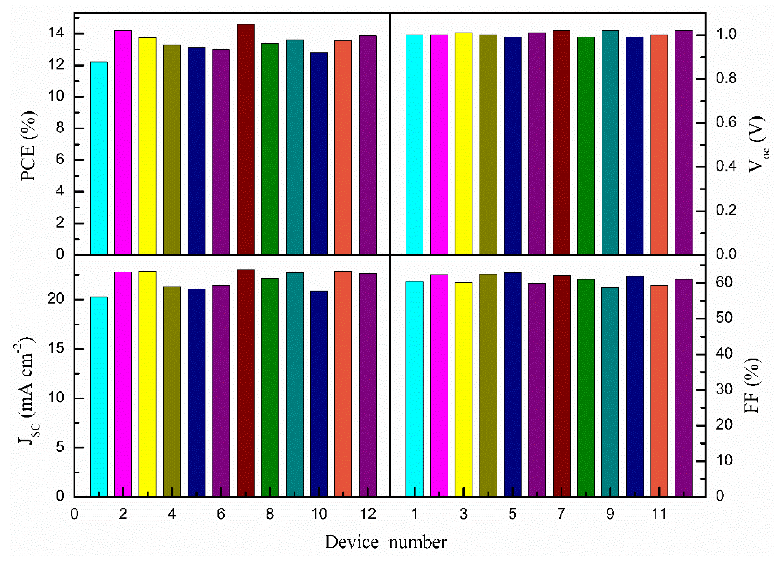
| Samples | VOC (V) | JSC (mA/cm2) | PCE (%) | FF (%) |
|---|---|---|---|---|
| 0% Ag@SiO2-TiO2 | 1.00 | 20.23 | 12.23 | 60.45 |
| 0.1% Ag@SiO2-TiO2 | 0.99 | 21.90 | 13.65 | 62.96 |
| 0.3% Ag@SiO2-TiO2 | 1.02 | 23.04 | 14.61 | 62.17 |
| 0.5% Ag@SiO2-TiO2 | 0.99 | 21.16 | 13.20 | 63.01 |
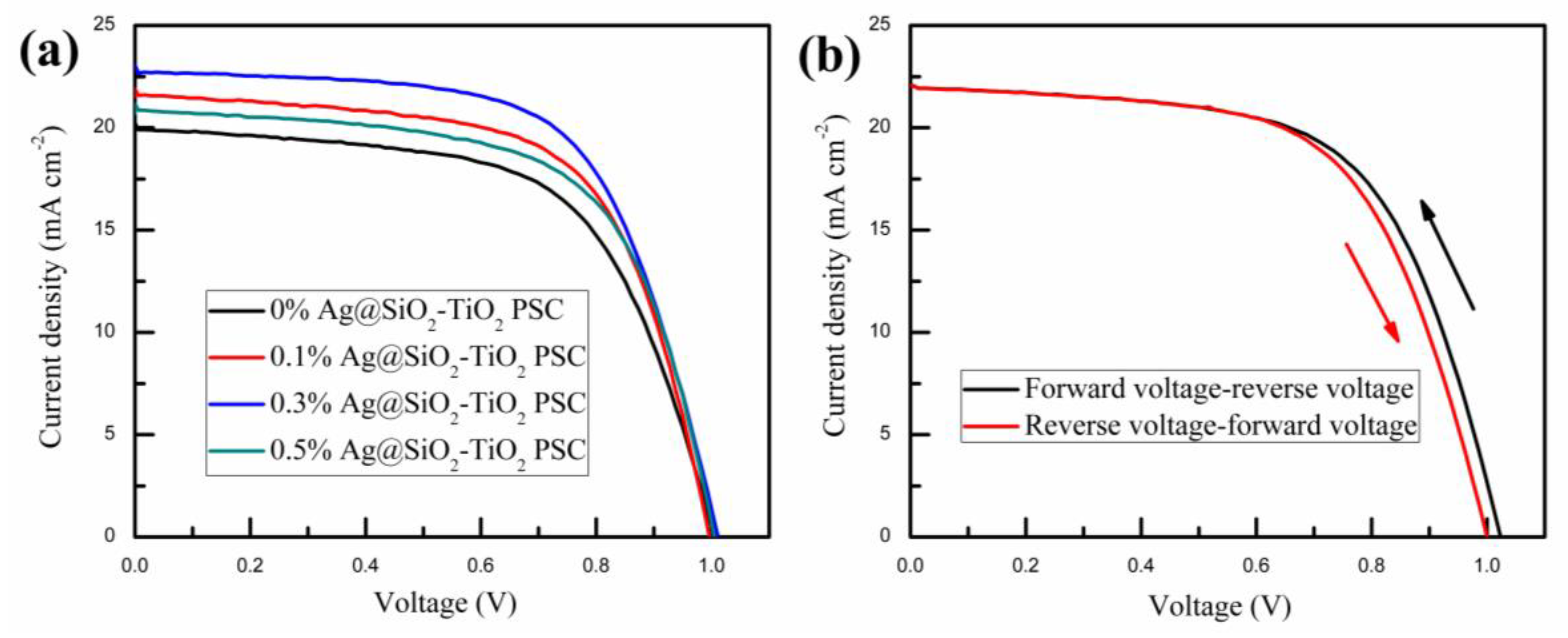
| Samples | VOC (V) | JSC (mA/cm2) | PCE (%) | FF (%) |
|---|---|---|---|---|
| Forward-reverse | 1.02 | 22.23 | 13.88 | 61.21 |
| Reverse- forward | 1.00 | 22.22 | 13.50 | 60.76 |
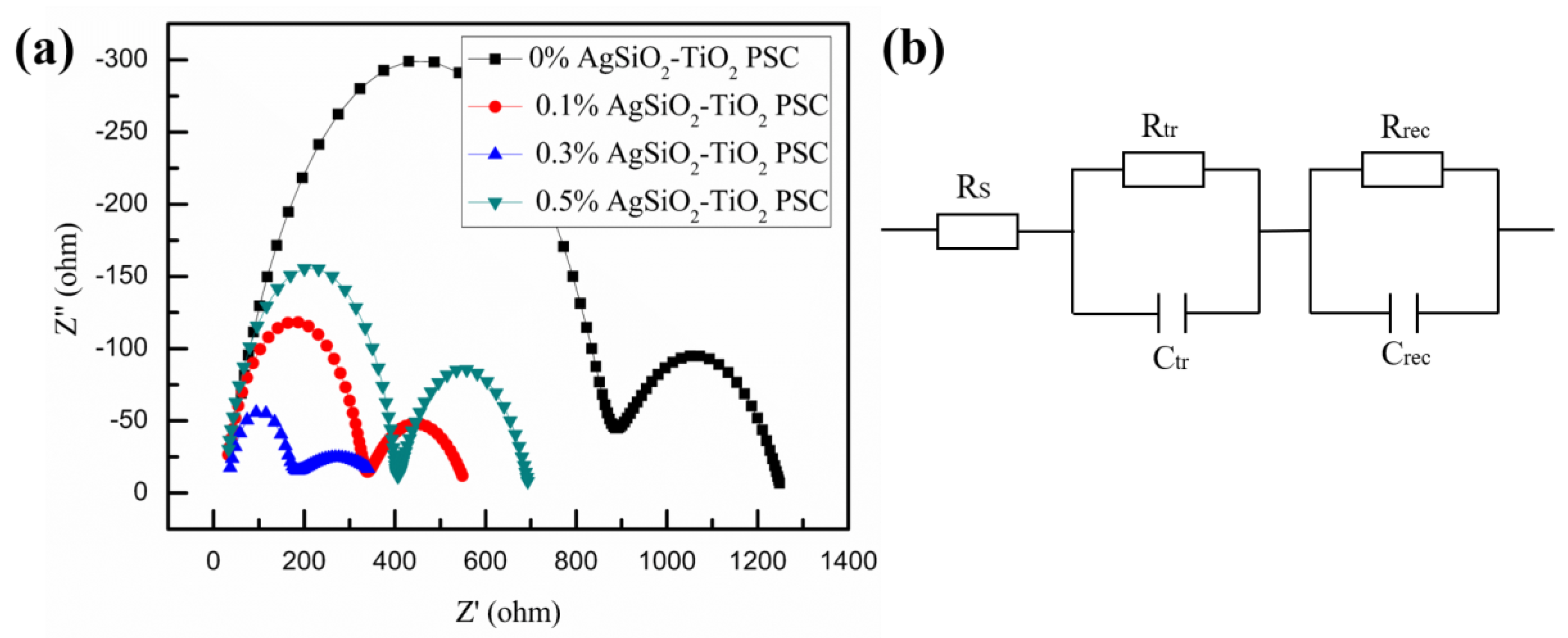
| Samples | RS (Ω) | Rtr (Ω) | Rrec (Ω) |
|---|---|---|---|
| 0% Ag@SiO2-TiO2 PSC | 29.75 | 842.4 | 381.6 |
| 0.1% Ag@SiO2-TiO2 PSC | 22.77 | 308.2 | 231.1 |
| 0.3% Ag@SiO2-TiO2 PSC | 25.02 | 125.8 | 243.0 |
| 0.5% Ag@SiO2-TiO2 PSC | 24.84 | 379.0 | 294.1 |
© 2018 by the authors. Licensee MDPI, Basel, Switzerland. This article is an open access article distributed under the terms and conditions of the Creative Commons Attribution (CC BY) license (http://creativecommons.org/licenses/by/4.0/).
Share and Cite
Wang, B.; Zhu, X.; Li, S.; Chen, M.; Lu, H.; Yang, Y. Ag@SiO2 Core-shell Nanoparticles Embedded in a TiO2 Mesoporous Layer Substantially Improve the Performance of Perovskite Solar Cells. Nanomaterials 2018, 8, 701. https://doi.org/10.3390/nano8090701
Wang B, Zhu X, Li S, Chen M, Lu H, Yang Y. Ag@SiO2 Core-shell Nanoparticles Embedded in a TiO2 Mesoporous Layer Substantially Improve the Performance of Perovskite Solar Cells. Nanomaterials. 2018; 8(9):701. https://doi.org/10.3390/nano8090701
Chicago/Turabian StyleWang, Bao, Xiangyu Zhu, Shuhan Li, Mengwei Chen, Haifei Lu, and Yingping Yang. 2018. "Ag@SiO2 Core-shell Nanoparticles Embedded in a TiO2 Mesoporous Layer Substantially Improve the Performance of Perovskite Solar Cells" Nanomaterials 8, no. 9: 701. https://doi.org/10.3390/nano8090701
APA StyleWang, B., Zhu, X., Li, S., Chen, M., Lu, H., & Yang, Y. (2018). Ag@SiO2 Core-shell Nanoparticles Embedded in a TiO2 Mesoporous Layer Substantially Improve the Performance of Perovskite Solar Cells. Nanomaterials, 8(9), 701. https://doi.org/10.3390/nano8090701