Improvement in Luminous Efficacy and Thermal Performance Using Quantum Dots Spherical Shell for White Light Emitting Diodes


Abstract
1. Introduction
2. Methods
3. Results and Discussion
4. Conclusions
Author Contributions
Funding
Conflicts of Interest
References
- Schubert, E.F.; Kim, J.K. Solid-state light sources getting smart. Science 2005, 308, 1274–1278. [Google Scholar] [CrossRef] [PubMed]
- Pust, P.; Schmidt, P.J.; Schnick, W. A revolution in lighting. Nat. Mater. 2015, 14, 454. [Google Scholar] [CrossRef] [PubMed]
- Pimputkar, S.; Speck, J.S.; Denbaars, S.P.; Nakamura, S. Prospects for LED lighting. Nat. Photonics 2009, 3, 180–182. [Google Scholar] [CrossRef]
- Jun, S.; Lee, J.; Jang, E. Highly luminescent and photostable quantum dot-silica monolith and its application to light-emitting diodes. Acs Nano 2013, 7, 1472. [Google Scholar] [CrossRef] [PubMed]
- Lin, H.Y.; Chen, K.J.; Wang, S.W.; Lin, C.C.; Wang, K.Y.; Li, J.R.; Lee, P.T.; Shih, M.H.; Li, X.; Chen, H.M. Improvement of light quality by DBR structure in white LED. Opt. Express 2015, 23, 24–30. [Google Scholar] [CrossRef] [PubMed]
- Wang, P.C.; Su, Y.K.; Lin, C.L.; Huang, G.S. Improving Performance and Reducing Amount of Phosphor Required in Packaging of White LEDs with TiO2-doped Silicone. IEEE Electron Device Lett. 2014, 35, 657–659. [Google Scholar]
- Anh, N.D.Q.; Lai, M.F.; Ma, H.Y.; Lee, H.Y. Enhancing of correlated color temperature uniformity for multi-chip white-light LEDs by adding SiO2 in phosphor layer. J. Chin. Inst. Eng. 2015, 38, 297–303. [Google Scholar]
- Chen, H.C.; Chen, K.J.; Wang, C.H.; Lin, C.C.; Yeh, C.C.; Tsai, H.H.; Shih, M.H.; Kuo, H.C.; Lu, T.C. A novel randomly textured phosphor structure for highly efficient white light-emitting diodes. Nanoscale Res. Lett. 2012, 7, 188. [Google Scholar] [CrossRef] [PubMed]
- Li, J.; Tang, Y.; Li, Z.; Ding, X.; Yu, S.; Yu, B. Improvement in Color-Conversion Efficiency and Stability for Quantum-Dot-Based Light-Emitting Diodes Using a Blue Anti-Transmission Film. Nanomaterials 2018, 8, 508. [Google Scholar] [CrossRef] [PubMed]
- Yu, S.; Li, Z.; Liang, G.; Tang, Y.; Yu, B.; Chen, K. Angular color uniformity enhancement of white light-emitting diodes by remote micro-patterned phosphor film. Photonics Res. 2016, 4, 140. [Google Scholar] [CrossRef]
- Lin, C.H.; Lin, D.W.; Chi, G.C.; Kuo, H.C.; Huang, H.W.; Huang, J.K.; Chen, J.R.; Lee, K.Y.; Shih, M.H.; Lee, P.T. Investigation and Comparison of the GaN-Based Light-Emitting Diodes Grown on High Aspect Ratio Nano-Cone and General Micro-Cone Patterned Sapphire Substrate. J. Disp. Technol. 2013, 9, 947–952. [Google Scholar]
- Zheng, X.G.; Wang, H.L.; Ding, G.Q.; Cui, G.L.; Chen, L.; Zhang, P.H.; Gong, Q.; Wang, S.M. Facile synthesis of highly graphitized nitrogen-doped carbon dots and carbon sheets with solid-state white-light emission. Mater. Lett. 2017, 195, 58–61. [Google Scholar] [CrossRef]
- Wang, X.; Li, W.; Sun, K. Stable efficient CdSe/CdS/ZnS core/multi-shell nanophosphors fabricated through a phosphine-free route for white light-emitting-diodes with high color rendering properties. J. Mater. Chem. 2011, 21, 8558–8565. [Google Scholar] [CrossRef]
- Muñozrosas, A.L.; Rodríguezgómez, A.; Alonsohuitrón, J.C. Enhanced Electroluminescence from Silicon Quantum Dots Embedded in Silicon Nitride Thin Films Coupled with Gold Nanoparticles in Light Emitting Devices. Nanomaterials 2018, 8, 182. [Google Scholar]
- Cheng, R.; Zhang, Y.; Lu, M.; Ji, C.; Sun, C.; Chen, X.; Chen, H.; Colvin, V.; Yu, W. White Light-Emitting Diodes Based on AgInS2/ZnS Quantum Dots with Improved Bandwidth in Visible Light Communication. Nanomaterials 2016, 6, 13. [Google Scholar]
- Xie, B.; Hu, R.; Yu, X.; Shang, B.; Ma, Y.; Luo, X. Effect of Packaging Method on Performance of Light-Emitting Diodes with Quantum Dot Phosphor. IEEE Photonics Technol. Lett. 2016, 28, 1115–1118. [Google Scholar] [CrossRef]
- Todescato, F.; Fortunati, I.; Minotto, A.; Signorini, R.; Jasieniak, J.J.; Bozio, R. Engineering of Semiconductor Nanocrystals for Light Emitting Applications. Materials 2016, 9, 672. [Google Scholar] [CrossRef] [PubMed]
- Lei, X.; Zheng, H.; Guo, X.; Chu, J.; Liu, S.; Liu, P. Optical Performance Enhancement of Quantum Dot-Based Light-Emitting Diodes Through an Optimized Remote Structure. IEEE Trans. Electr. Devices 2016, 63, 691–697. [Google Scholar] [CrossRef]
- Song, W.S.; Yang, H. Efficient White-Light-Emitting Diodes Fabricated from Highly Fluorescent Copper Indium Sulfide Core/Shell Quantum Dots. Chem. Mater. 2012, 24, 1961–1967. [Google Scholar] [CrossRef]
- Chen, J.; Hardev, V.; Hartlove, J.; Hofler, J.; Lee, E. A High-Efficiency Wide-Color-Gamut Solid-State Backlight System for LCDs Using Quantum Dot Enhancement Film. Sid Symp. Dig. Tech. Pap. 2012, 43, 895–896. [Google Scholar] [CrossRef]
- Chen, H.; He, J.; Wu, S.T. Recent Advances on Quantum-Dot-Enhanced Liquid-Crystal Displays. IEEE J. Sel. Top. Quant. Electron. 2017, 23, 1–11. [Google Scholar] [CrossRef]
- Zhu, R.; Luo, Z.; Chen, H.; Dong, Y.; Wu, S.T. Realizing Rec. 2020 color gamut with quantum dot displays. Opt. Express 2015, 23, 23680–23693. [Google Scholar] [CrossRef] [PubMed]
- Tang, Y.; Li, Z.; Li, Z.T.; Li, J.S.; Yu, S.D.; Rao, L.S. Enhancement of Luminous Efficiency and Uniformity of CCT for Quantum Dot-Converted LEDs by Incorporating With ZnO Nanoparticles. IEEE Trans. Electron Devices 2018, 65, 158–164. [Google Scholar] [CrossRef]
- Woo, J.Y.; Kim, K.N.; Jeong, S.; Han, C.S. Thermal behavior of a quantum dot nanocomposite as a color converting material and its application to white LED. Nanotechnology 2010, 21, 495704. [Google Scholar] [CrossRef] [PubMed]
- Tsai, P.Y.; Huang, H.K.; Sung, J.M.; Kan, M.C.; Wang, Y.H. High Thermal Stability and Wide Angle of White Light Chip-on-Board Package Using a Remote Phosphor Structure. IEEE Electron Device Lett. 2015, 36, 250–252. [Google Scholar] [CrossRef]
- Chen, K.J.; Chen, H.C.; Shih, M.H.; Wang, C.H.; Kuo, M.Y.; Yang, Y.C.; Lin, C.C.; Kuo, H.C. The Influence of the Thermal Effect on CdSe/ZnS Quantum Dots in Light-Emitting Diodes. J. Lightwave Technol. 2012, 30, 2256–2261. [Google Scholar] [CrossRef]
- Shin, M.H.; Hong, H.G.; Kim, H.J.; Kim, Y.J. Enhancement of optical extraction efficiency in white LED package with quantum dot phosphors and air-gap structure. Appl. Phys. Express 2014, 7, 052101. [Google Scholar] [CrossRef]
- Yin, L.; Bai, Y.; Zhou, J.; Cao, J.; Sun, X.; Zhang, J. The thermal stability performances of the color rendering index of white light emitting diodes with the red quantum dots encapsulation. Opt. Mater. 2015, 42, 187–192. [Google Scholar] [CrossRef]
- Li, J.-S.; Tang, Y.; Li, Z.-T.; Cao, K.; Yan, C.-M.; Ding, X.-R. Full spectral optical modeling of quantum-dot-converted elements for light-emitting diodes considering reabsorption and reemission effect. Nanotechnology 2018, 29, 295707. [Google Scholar] [CrossRef] [PubMed]
- Ding, X.; Li, J.; Chen, Q.; Tang, Y.; Li, Z.; Yu, B. Improving LED CCT uniformity using micropatterned films optimized by combining ray tracing and FDTD methods. Opt. Express 2015, 23, 180–191. [Google Scholar] [CrossRef] [PubMed]
- Li, J.S.; Tang, Y.; Li, Z.T.; Ding, X.R.; Rao, L.S.; Yu, B.H. Effect of Quantum Dot Scattering and Absorption on the Optical Performance of White Light-Emitting Diodes. IEEE Trans. Electron Devices 2018, 7, 2877–2884. [Google Scholar] [CrossRef]
- Kim, Y.K.; Choi, K.C.; Baek, Y.K.; Shin, P.W. Enhanced luminescence stability of quantum dot-based inorganic nanocomposite particles for white-light-emitting diodes. Mater. Lett. 2014, 124, 129–132. [Google Scholar] [CrossRef]
- Hsu, S.C.; Chen, Y.H.; Tu, Z.Y.; Han, H.V.; Lin, S.L.; Chen, T.M.; Kuo, H.C.; Lin, C.C. Highly Stable and Efficient Hybrid Quantum Dot Light-Emitting Diodes. IEEE Photonics J. 2015, 7, 1–10. [Google Scholar] [CrossRef]


| Sample | Planar-COB | Sphere-COB |
|---|---|---|
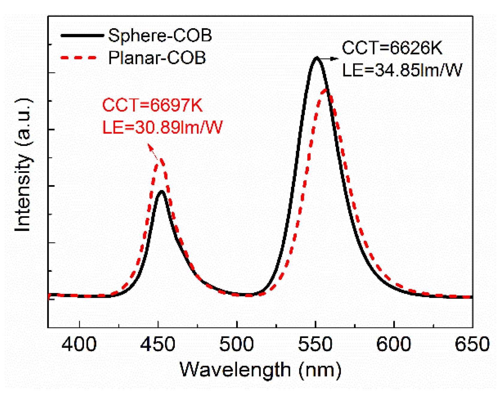
| Luminous efficacy (lm/W) | 30.89 | 34.85 |
| Improved LE (%) | Reference | 12.9 |
| Chromaticity coordinate (X) | 0.299 | 0.290 |
| Chromaticity coordinate (Y) | 0.394 | 0.461 |
| CCT (K) | 6626 | 6697 |
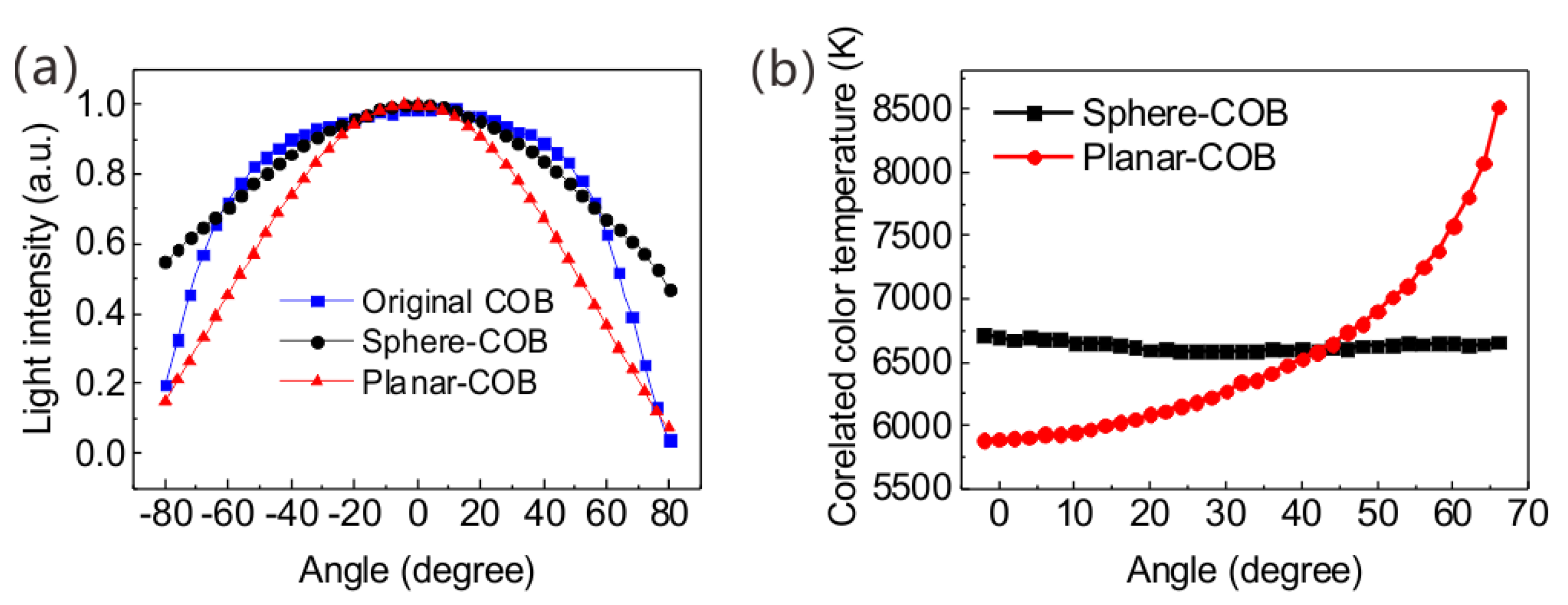
| ΔCCT (K) | 2642 | 283 |
| Beam angle (°) | 115 | 160 |
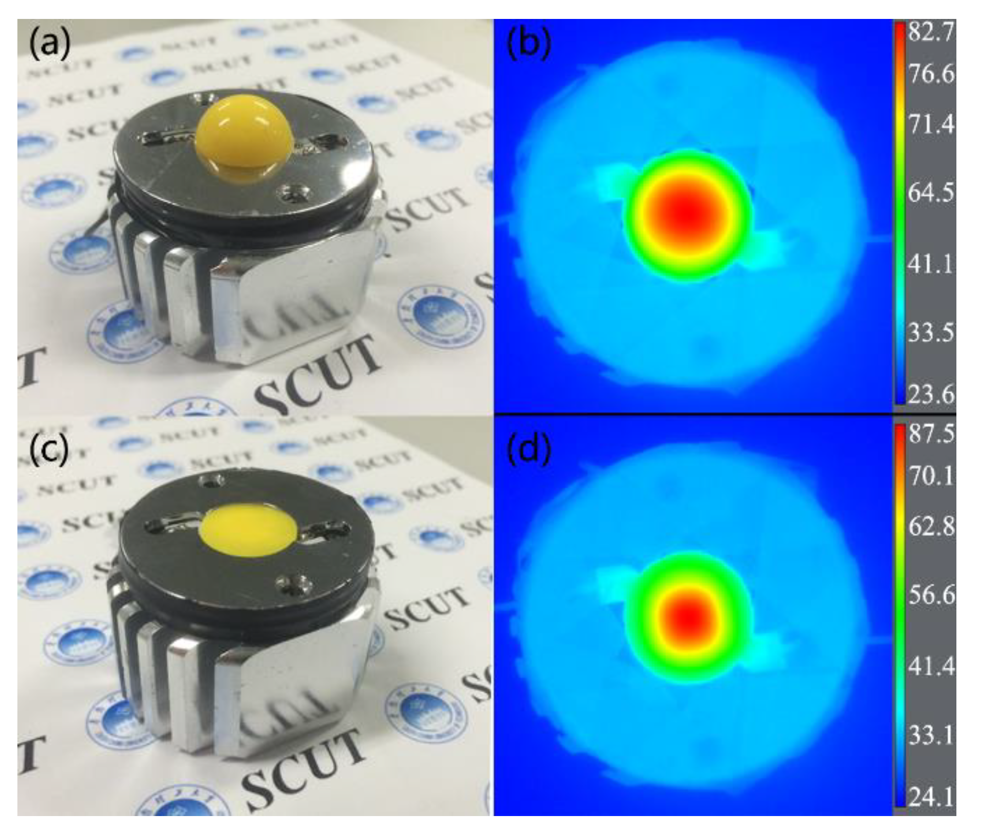
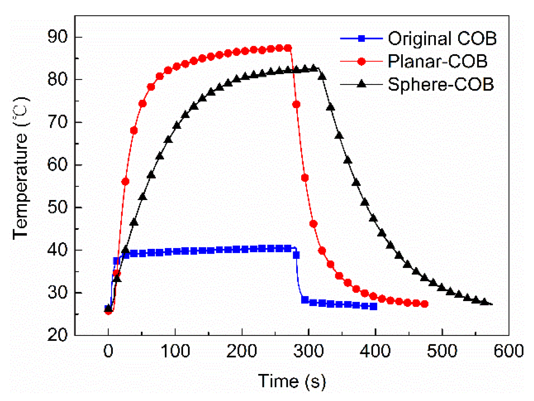
| Highest temperature (°C) | 87.5 | 82.7 |
| Decreased temperature (°C) | Reference | 4.8 |
© 2018 by the authors. Licensee MDPI, Basel, Switzerland. This article is an open access article distributed under the terms and conditions of the Creative Commons Attribution (CC BY) license (http://creativecommons.org/licenses/by/4.0/).
Share and Cite
Chen, S.; Yan, C.; Tang, Y.; Li, J.; Ding, X.; Rao, L.; Li, Z. Improvement in Luminous Efficacy and Thermal Performance Using Quantum Dots Spherical Shell for White Light Emitting Diodes. Nanomaterials 2018, 8, 618. https://doi.org/10.3390/nano8080618
Chen S, Yan C, Tang Y, Li J, Ding X, Rao L, Li Z. Improvement in Luminous Efficacy and Thermal Performance Using Quantum Dots Spherical Shell for White Light Emitting Diodes. Nanomaterials. 2018; 8(8):618. https://doi.org/10.3390/nano8080618
Chicago/Turabian StyleChen, Songmao, Caiman Yan, Yong Tang, Jiasheng Li, Xinrui Ding, Longshi Rao, and Zongtao Li. 2018. "Improvement in Luminous Efficacy and Thermal Performance Using Quantum Dots Spherical Shell for White Light Emitting Diodes" Nanomaterials 8, no. 8: 618. https://doi.org/10.3390/nano8080618
APA StyleChen, S., Yan, C., Tang, Y., Li, J., Ding, X., Rao, L., & Li, Z. (2018). Improvement in Luminous Efficacy and Thermal Performance Using Quantum Dots Spherical Shell for White Light Emitting Diodes. Nanomaterials, 8(8), 618. https://doi.org/10.3390/nano8080618