Effect of Graphene Nanowall Size on the Interfacial Strength of Carbon Fiber Reinforced Composites

 ,
,  ,
, 
Abstract
1. Introduction
2. Experimental Section
2.1. Materials
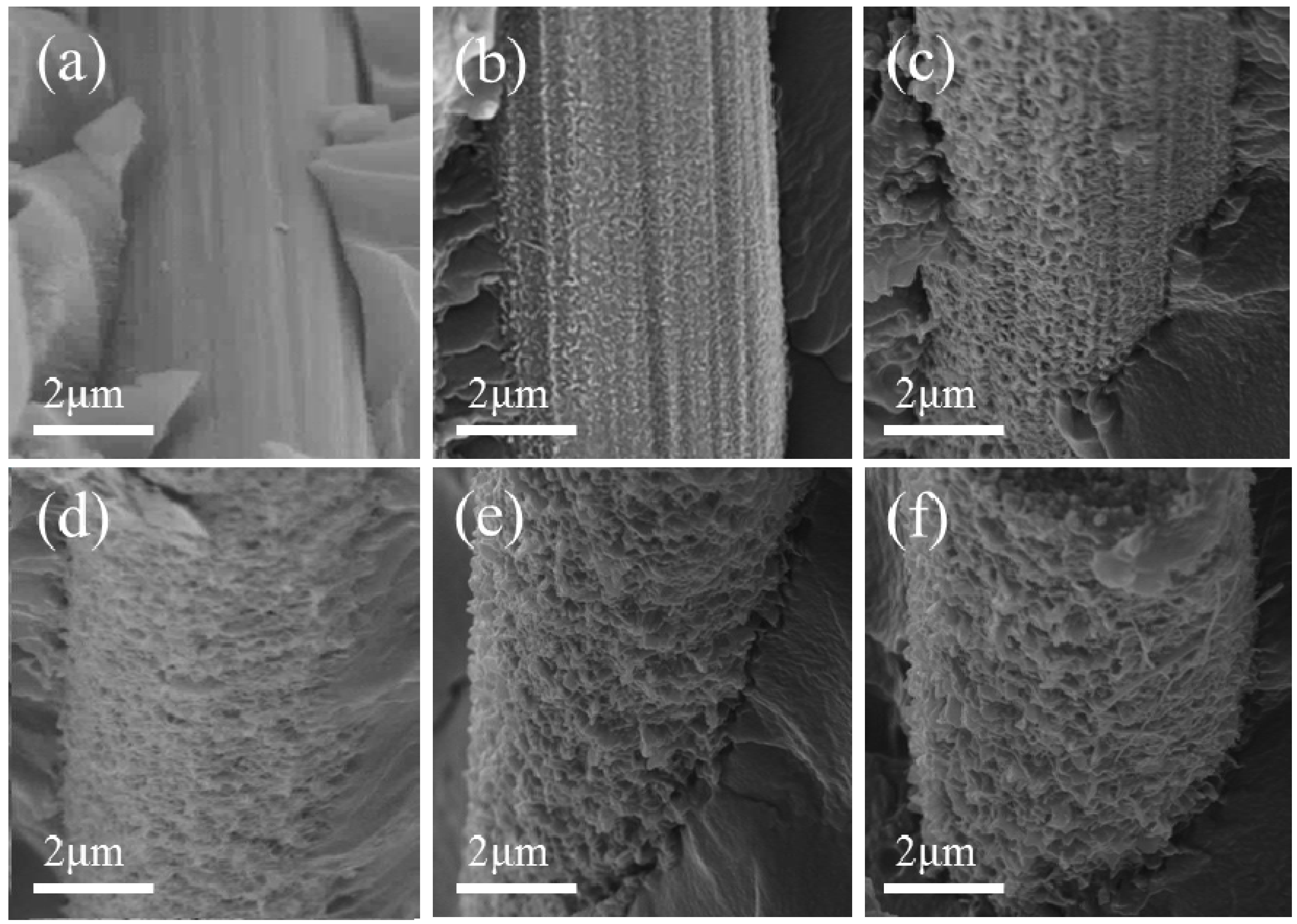
2.2. Graphene Nanowalls (GNWs) Growth on Carbon Fiber (CF)
2.3. Sample Preparation for Single-Fiber Segmentation Test
2.4. Sample Preparation for Three-Point Short Beam Shear Test
2.5. Characterization
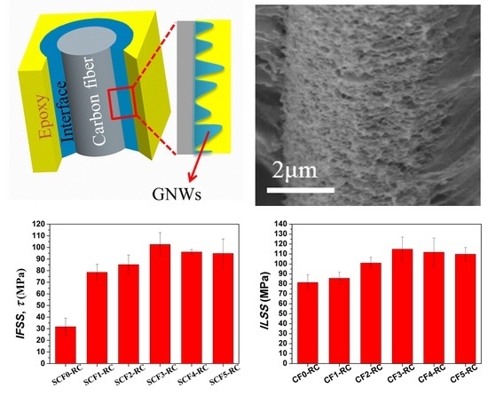
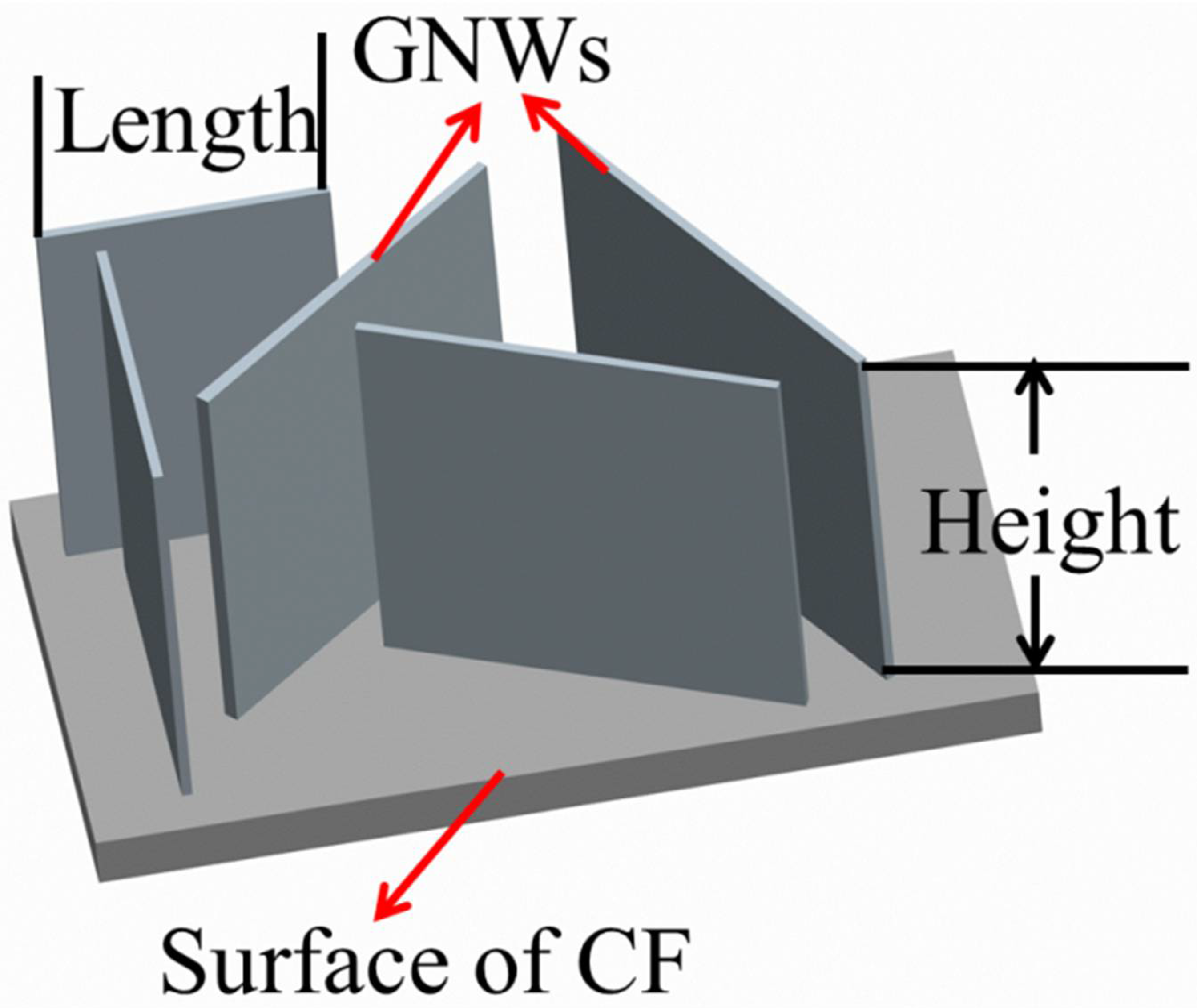
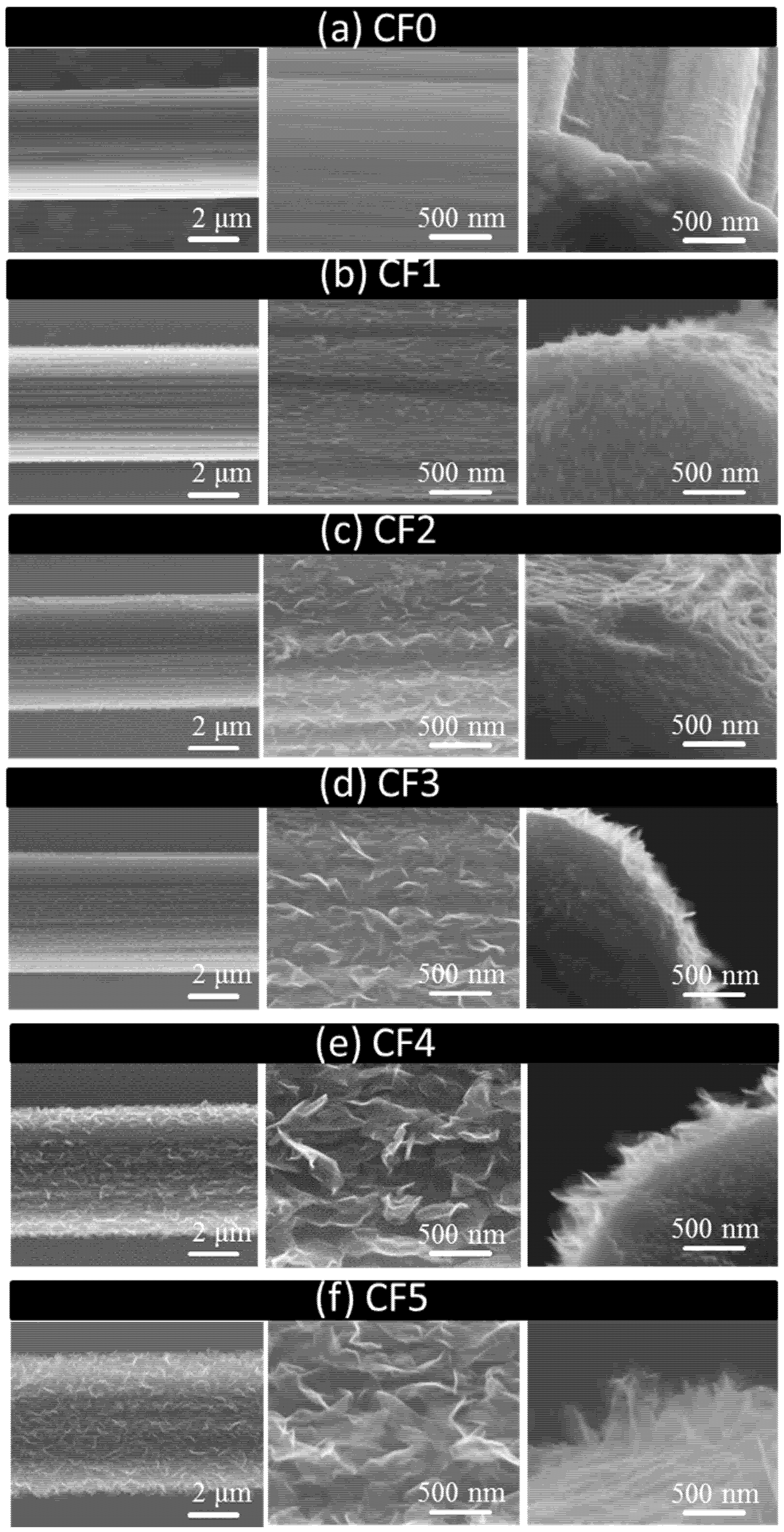
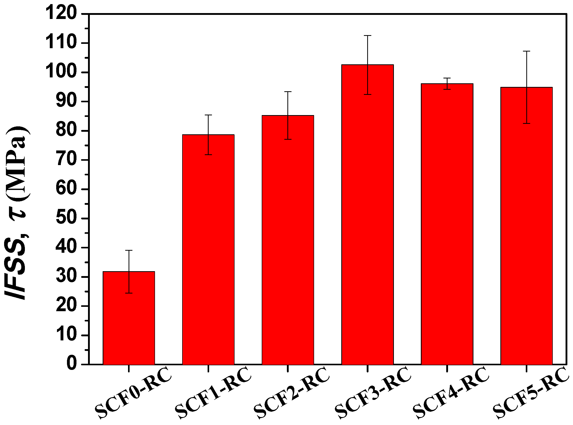
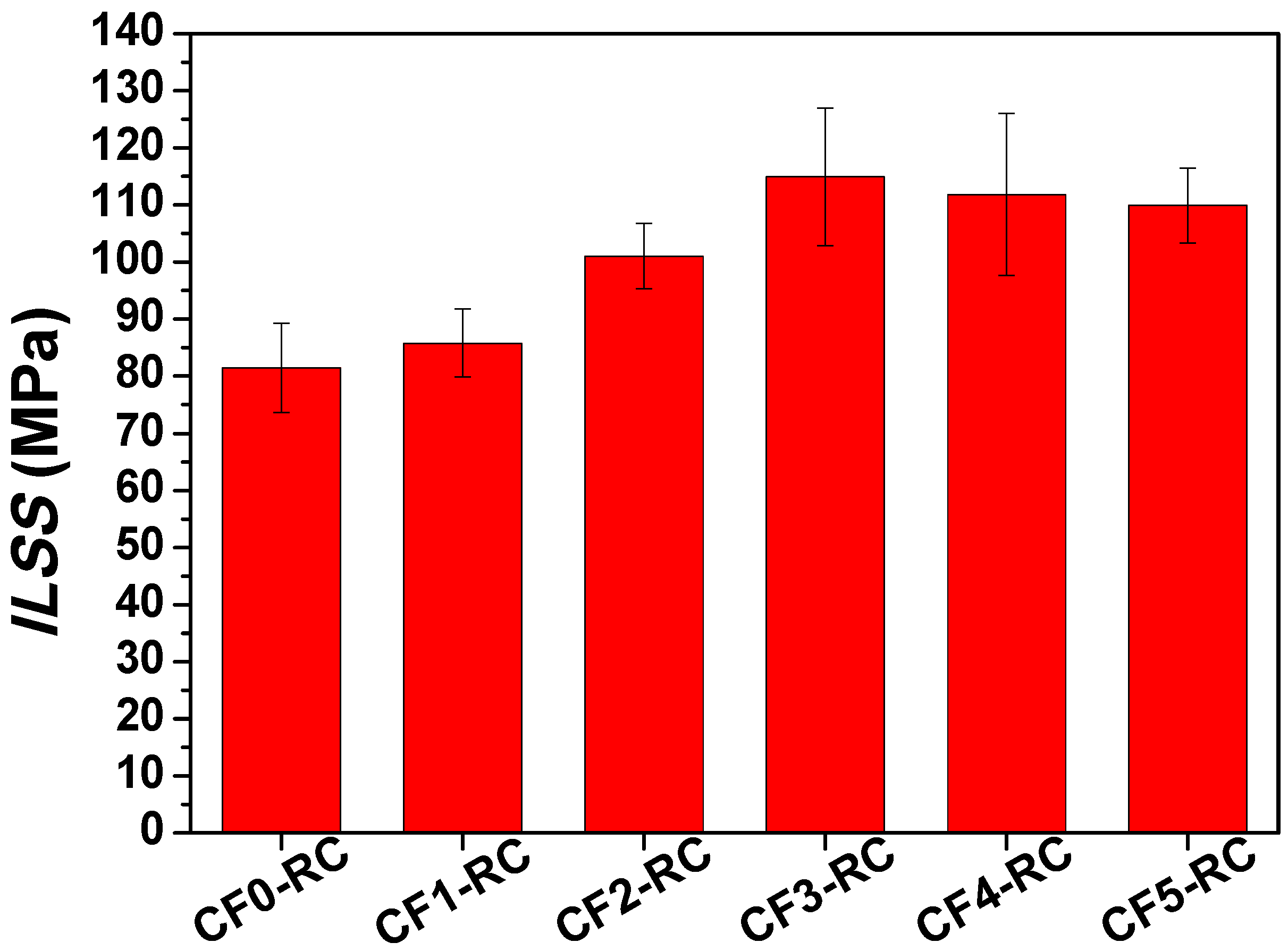
3. Results and Discussion
4. Conclusions
Author Contributions
Acknowledgments
Conflicts of Interest
References
- Zhang, R.L.; Gao, B.; Ma, Q.H.; Zhang, J.; Cui, H.Z.; Liu, L. Directly grafting graphene oxide onto carbon fiber and the effect on the mechanical properties of carbon fiber composites. Mater. Des. 2016, 93, 364–369. [Google Scholar] [CrossRef]
- Vautard, F.; Ozcan, S.; Paulauskas, F.; Spruiell, J.E.; Meyer, H.; Lance, M.J. Influence of the carbon fiber surface microstructure on the surface chemistry generated by a thermo-chemical surface treatment. Appl. Surf. Sci. 2012, 261, 473–480. [Google Scholar] [CrossRef]
- Jones, A.R.; Cintora, A.; White, S.R.; Sottos, N.R. Autonomic Healing of Carbon Fiber/Epoxy Interfaces. ACS Appl. Mater. Interfaces 2014, 6, 6033–6039. [Google Scholar] [CrossRef] [PubMed]
- Yu, K.; Wang, M.; Wu, J.; Qian, K.; Sun, J.; Lu, X. Modification of the Interfacial Interaction between Carbon Fiber and Epoxy with Carbon Hybrid Materials. Nanomaterials 2016, 6, 89. [Google Scholar] [CrossRef] [PubMed]
- Liu, D.; Li, B.; Li, G.; Wang, L.; Yang, X. Tagged and enhanced interface of carbon fiber/epoxy by doping sizing agent with upconversion luminescent nanoparticles. Mater. Lett. 2017, 196, 37–41. [Google Scholar] [CrossRef]
- Sun, J.; Zhao, F.; Yao, Y.; Liu, X.; Jin, Z.; Huang, Y. A two-step method for high efficient and continuous carbon fiber treatment with enhanced fiber strength and interfacial adhesion. Mater. Lett. 2017, 196, 46–49. [Google Scholar] [CrossRef]
- Sharma, M.; Gao, S.; Mäder, E.; Sharma, H.; Wei, L.Y.; Bijwe, J. Carbon fiber surfaces and composite interphases. Compos. Sci. Technol. 2014, 102, 35–50. [Google Scholar] [CrossRef]
- Zhao, F.; Huang, Y.; Liu, L.; Bai, Y.; Xu, L. Formation of a carbon fiber/polyhedral oligomeric silsesquioxane/carbon nanotube hybrid reinforcement and its effect on the interfacial properties of carbon fiber/epoxy composites. Carbon 2011, 49, 2624–2632. [Google Scholar] [CrossRef]
- Ren, C.; Gong, Q.M.; Guo, L.Q.; Zhao, X.M.; Liang, J. Analyses of reinforcing effects of in situ grown CNTs on carbon fibre fabric/epoxy composites at micro- and macroscale. Micro Nano Lett. 2012, 7, 240–243. [Google Scholar] [CrossRef]
- Sharma, S.P.; Lakkad, S.C. Effect of CNTs growth on carbon fibers on the tensile strength of CNTs grown carbon fiber-reinforced polymer matrix composites. Compos. Part A Appl. Sci. Manuf. 2011, 42, 8–15. [Google Scholar] [CrossRef]
- An, Q.; Rider, A.N.; Thostenson, E.T. Electrophoretic deposition of carbon nanotubes onto carbon-fiber fabric for production of carbon/epoxy composites with improved mechanical properties. Carbon 2012, 50, 4130–4143. [Google Scholar] [CrossRef]
- Wang, Y.L.; Pillai, S.K.R.; Che, J.F.; Chan-Park, M.B. High Interlaminar Shear Strength Enhancement of Carbon Fiber/Epoxy Composite through Fiber- and Matrix-Anchored Carbon Nanotube Networks. ACS Appl. Mater. Interfaces 2017, 9, 8960–8966. [Google Scholar] [CrossRef] [PubMed]
- Lin, Y.; Ehlert, G.; Sodano, H.A. Increased Interface Strength in Carbon Fiber Composites through a ZnO Nanowire Interphase. Adv. Funct. Mater. 2009, 19, 2654–2660. [Google Scholar] [CrossRef]
- Kowbel, W.; Bruce, C.; Withers, J.C.; Ransone, P.O. Effect of carbon fabric whiskerization on mechanical properties of C-C composites. Compos. Part A Appl. Sci. Manuf. 1997, 28, 993–1000. [Google Scholar] [CrossRef]
- Zhang, X.; Fan, X.; Yan, C.; Li, H.; Zhu, Y.; Li, X.; Yu, L. Interfacial microstructure and properties of carbon fiber composites modified with graphene oxide. ACS Appl. Mater. Interfaces 2012, 4, 1543–1552. [Google Scholar] [CrossRef] [PubMed]
- Zhang, Q.; Jiang, D.; Liu, L.; Huang, Y.; Long, J.; Wu, G.; Wu, Z.; Umar, A.; Guo, J.; Zhang, X.; et al. Effects of Graphene Oxide Modified Sizing Agents on Interfacial Properties of Carbon Fibers/Epoxy Composites. J. Nanosci. Nanotechnol. 2015, 15, 9807–9811. [Google Scholar] [CrossRef] [PubMed]
- Li, F.; Liu, Y.; Qu, C.-B.; Xiao, H.-M.; Hua, Y.; Sui, G.-X.; Fu, S.-Y. Enhanced mechanical properties of short carbon fiber reinforced polyethersulfone composites by graphene oxide coating. Polymer 2015, 59, 155–165. [Google Scholar] [CrossRef]
- Lisi, N.; Giorgi, R.; Re, M.; Dikonimos, T.; Giorgi, L.; Salernitano, E.; Gagliardi, S.; Tatti, F. Carbon nanowall growth on carbon paper by hot filament chemical vapour deposition and its microstructure. Carbon 2011, 49, 2134–2140. [Google Scholar] [CrossRef]
- Hiramatsu, M.; Mitsuguchi, S.; Horibe, T.; Kondo, H.; Hori, M.; Kano, H. Fabrication of Carbon Nanowalls on Carbon Fiber Paper for Fuel Cell Application. Jpn. J. Appl. Phys. 2013, 52. [Google Scholar] [CrossRef]
- Song, X.F.; Liu, J.; Yu, L.Y.; Yang, J.; Fang, L.; Shi, H.F.; Du, C.L.; Wei, D.P. Direct versatile PECVD growth of graphene nanowalls on multiple substrates. Mater. Lett. 2014, 137, 25–28. [Google Scholar] [CrossRef]
- Chi, Y.; Chu, J.; Chen, M.; Li, C.; Mao, W.; Piao, M.; Zhang, H.; Liu, B.S.; Shi, H. Directly deposited graphene nanowalls on carbon fiber for improving the interface strength in composites. Appl. Phys. Lett. 2016, 108, 211601. [Google Scholar] [CrossRef]
- ISO 527-2. Plastics—Determination of Tensile Properties—Part 2: Test Conditions for Moulding and Extrusion Plastics; International Organization for Standardization: Geveva, Switzerland, 2012. [Google Scholar]
- ASTM D3379-75. Standard Test Method for Tensile Strength and Young’s Modulus for High-Modulus Single-Filament Materials; ASTM International: West Conshohocken, PA, USA, 1989. [Google Scholar]
- Kelly, A.; Tyson, W.R. Tensile Properties of Fibre-Reinforced Metals—Copper/Tungsten and Copper/Molybdenum. J. Mech. Phys. Solids 1965, 13, 329–350. [Google Scholar] [CrossRef]
- Wimolkiatisak, A.S.; Bell, J.P. Interfacial Shear-Strength and Failure Modes of Interphase-Modified Graphite-Epoxy Composites. Polym. Compos. 1989, 10, 162–172. [Google Scholar] [CrossRef]
- ASTM D2344. Standard Test Method for Short-Beam Strength of Polymer Matrix Composite Materials and Their Laminates; ASTM International: West Conshohocken, PA, USA, 2016. [Google Scholar]
- Dong, J.D.; Jia, C.Y.; Wang, M.Q.; Fang, X.J.; Wei, H.W.; Xie, H.Q.; Zhang, T.; He, J.M.; Jiang, Z.X.; Huang, Y.D. Improved mechanical properties of carbon fiber-reinforced epoxy composites by growing carbon black on carbon fiber surface. Compos. Sci. Technol. 2017, 149, 75–80. [Google Scholar] [CrossRef]
- Yao, X.; Gao, X.; Jiang, J.; Xu, C.; Deng, C.; Wang, J. Comparison of carbon nanotubes and graphene oxide coated carbon fiber for improving the interfacial properties of carbon fiber/epoxy composites. Compos. Part B Eng. 2018, 132, 170–177. [Google Scholar] [CrossRef]
- Hiramatsu, M.; Kondo, H.; Hori, M.; Gong, J.R. New Progress on Graphene Research; InTech: Rijeka, Croatia, 2013; Volume, Chapter 9. [Google Scholar]
- Eckmann, A.; Felten, A.; Mishchenko, A.; Britnell, L.; Krupke, R.; Novoselov, K.S.; Casiraghi, C. Probing the nature of defects in graphene by Raman spectroscopy. Nano Lett. 2012, 12, 3925–3930. [Google Scholar] [CrossRef] [PubMed]
- Ferrari, A.C. Raman spectroscopy of graphene and graphite: Disorder, electron-phonon coupling, doping and nonadiabatic effects. Solid State Commun. 2007, 143, 47–57. [Google Scholar] [CrossRef]
- Hui, C.Y.; Phoenix, S.L.; Shia, D. The single-filament-composite test: A new statistical theory for estimating the interfacial shear strength and Weibull parameters for fiber strength. Compos. Sci. Technol. 1997, 57, 1707–1725. [Google Scholar] [CrossRef]
- Wang, C.F.; Li, J.; Yu, J.L.; Sun, S.F.; Li, X.Y.; Xie, F.; Jiang, B.; Wu, G.S.; Yu, F.; Huang, Y.D. Grafting of size-controlled graphene oxide sheets onto carbon fiber for reinforcement of carbon fiber/epoxy composite interfacial strength. Compos. Part A Appl. Sci. Manuf. 2017, 101, 511–520. [Google Scholar] [CrossRef]
- Wang, X.; Jin, J.; Song, M. An investigation of the mechanism of graphene toughening epoxy. Carbon 2013, 65, 324–333. [Google Scholar] [CrossRef]
- De Cicco, D.; Asaee, Z.; Taheri, F. Use of Nanoparticles for Enhancing the Interlaminar Properties of Fiber-Reinforced Composites and Adhesively Bonded Joints—A Review. Nanomaterials 2017, 7, 360. [Google Scholar] [CrossRef] [PubMed]


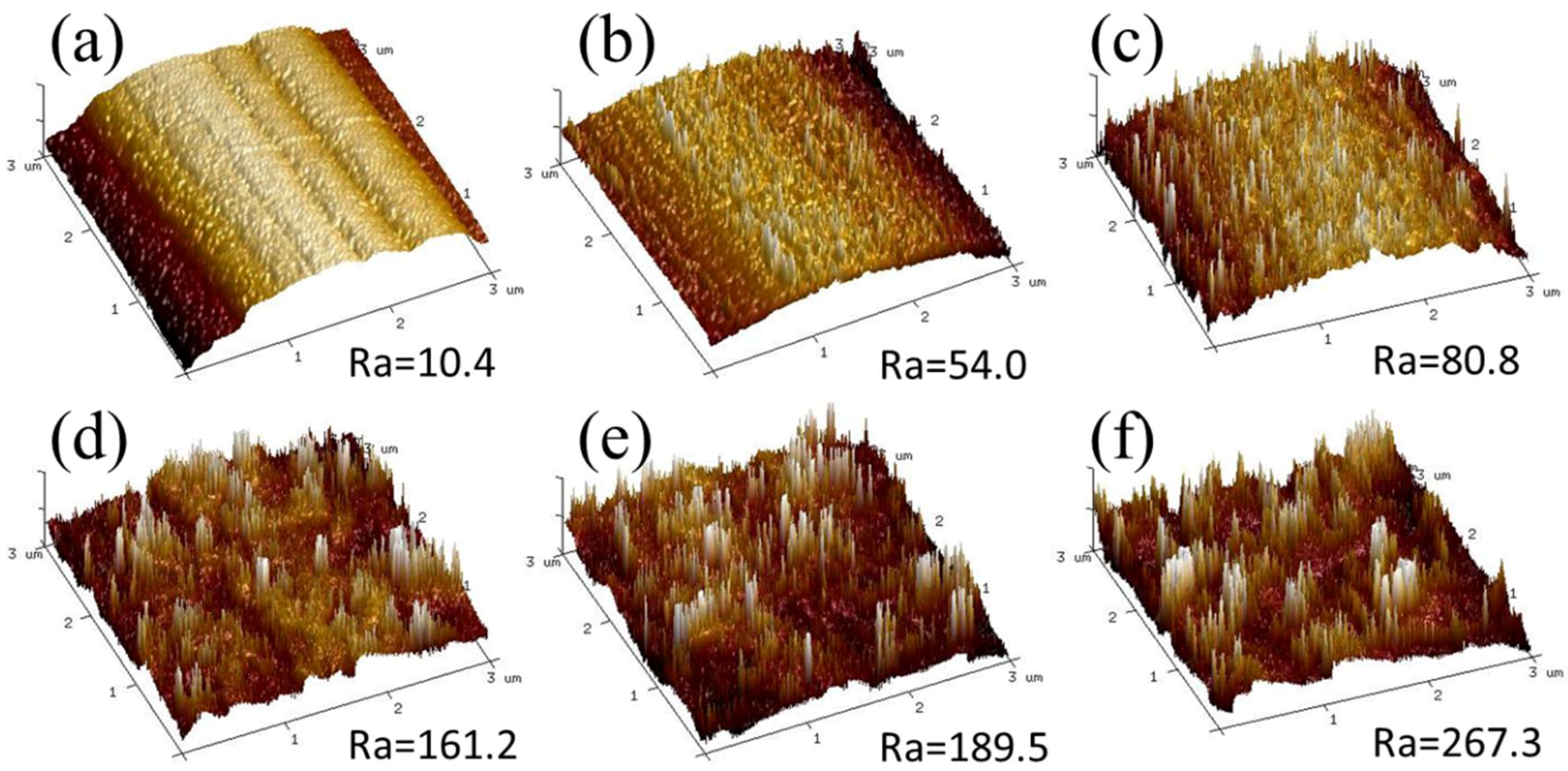
| Parameter | CF-0 | CF-1 | CF-2 | CF-3 | CF-4 | CF-5 |
|---|---|---|---|---|---|---|
| Growth time (min) | 0 | 15 | 30 | 45 | 60 | 90 |
| GNW length (nm) | 0 | 66 | 150 | 195 | 263 | 326 |
| GNW height (nm) | 0 | 60 | 99 | 212 | 407 | 618 |
| σf (GPa) | 3.60 ± 0.65 | 3.26 ± 0.64 | 3.31 ± 0.68 | 3.41 ± 0.74 | 3.48 ± 0.64 | 3.41 ± 0.69 |
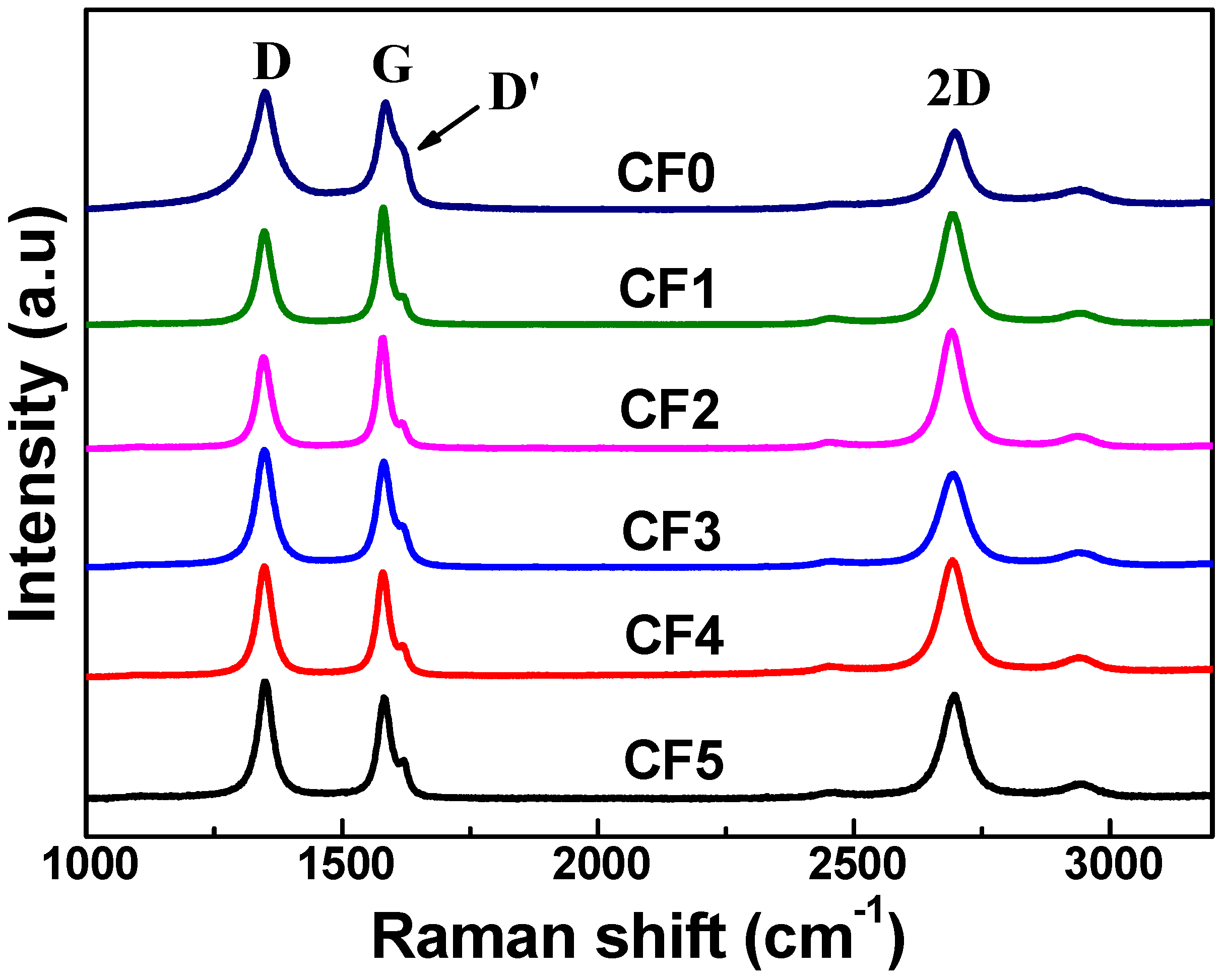
| Parameter | CF-0 | CF-1 | CF-2 | CF-3 | CF-4 | CF-5 |
|---|---|---|---|---|---|---|
| I(D)/I(D’) | 1.71 | 3.05 | 3.20 | 2.93 | 3.12 | 2.98 |
| I(D)/I(G) | 1.09 | 0.80 | 0.82 | 1.08 | 1.11 | 1.20 |
| I(G)/I(2D) | 1.20 | 1.05 | 0.97 | 1.09 | 0.94 | 0.96 |
| FWHM (2D)(cm−1) | 55.5 | 54.7 | 52.9 | 56.3 | 57.4 | 53.5 |
© 2018 by the authors. Licensee MDPI, Basel, Switzerland. This article is an open access article distributed under the terms and conditions of the Creative Commons Attribution (CC BY) license (http://creativecommons.org/licenses/by/4.0/).
Share and Cite
Wang, X.; Li, C.; Chi, Y.; Piao, M.; Chu, J.; Zhang, H.; Li, Z.; Wei, W. Effect of Graphene Nanowall Size on the Interfacial Strength of Carbon Fiber Reinforced Composites. Nanomaterials 2018, 8, 414. https://doi.org/10.3390/nano8060414
Wang X, Li C, Chi Y, Piao M, Chu J, Zhang H, Li Z, Wei W. Effect of Graphene Nanowall Size on the Interfacial Strength of Carbon Fiber Reinforced Composites. Nanomaterials. 2018; 8(6):414. https://doi.org/10.3390/nano8060414
Chicago/Turabian StyleWang, Xiao, Chaolong Li, Yao Chi, Mingxing Piao, Jin Chu, Heng Zhang, Zhenghao Li, and Wei Wei. 2018. "Effect of Graphene Nanowall Size on the Interfacial Strength of Carbon Fiber Reinforced Composites" Nanomaterials 8, no. 6: 414. https://doi.org/10.3390/nano8060414
APA StyleWang, X., Li, C., Chi, Y., Piao, M., Chu, J., Zhang, H., Li, Z., & Wei, W. (2018). Effect of Graphene Nanowall Size on the Interfacial Strength of Carbon Fiber Reinforced Composites. Nanomaterials, 8(6), 414. https://doi.org/10.3390/nano8060414