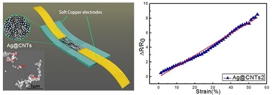
Highly Sensitive and Stretchable Strain Sensor Based on Ag@CNTs


 ,
,
Abstract
:
1. Introduction
2. Experimental Section
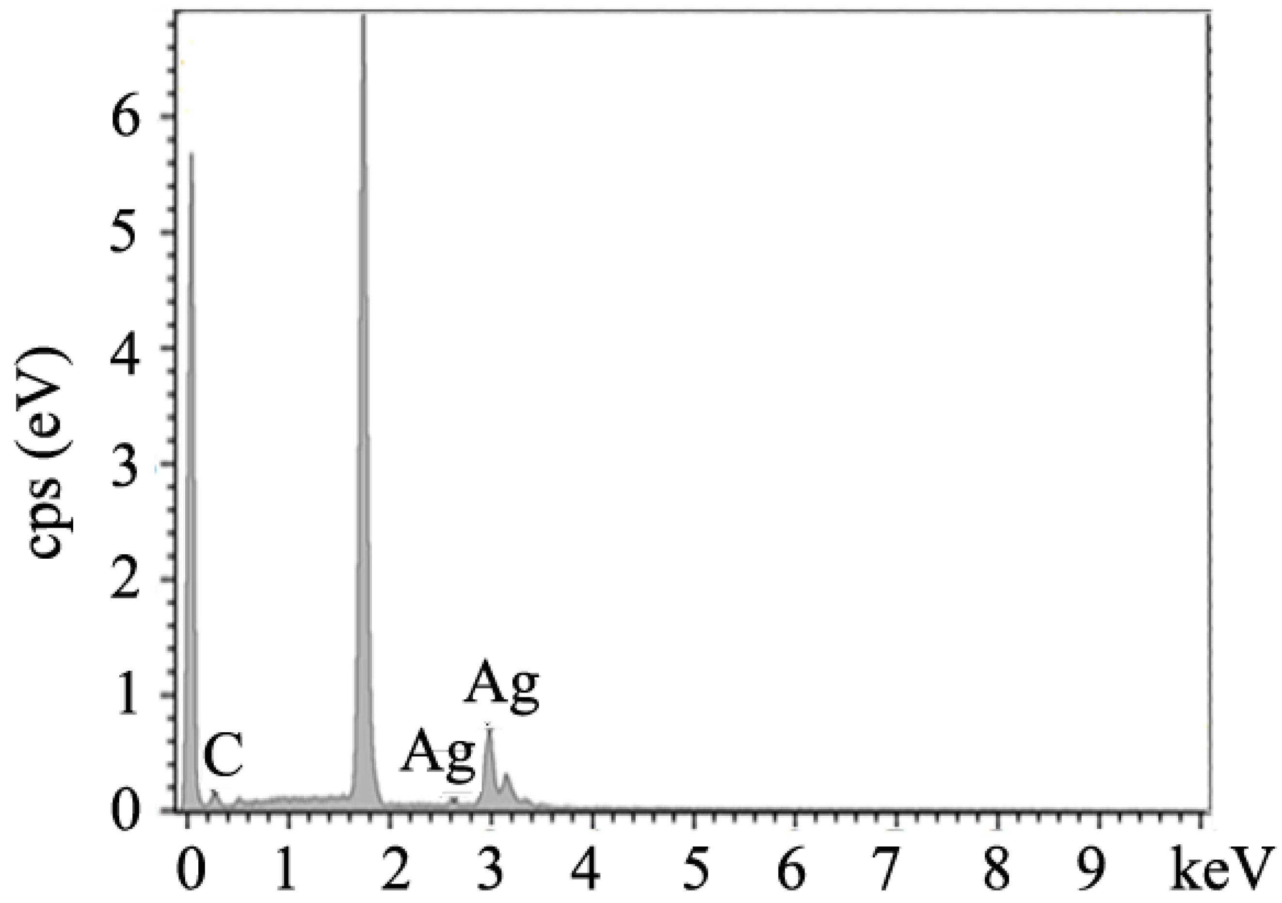
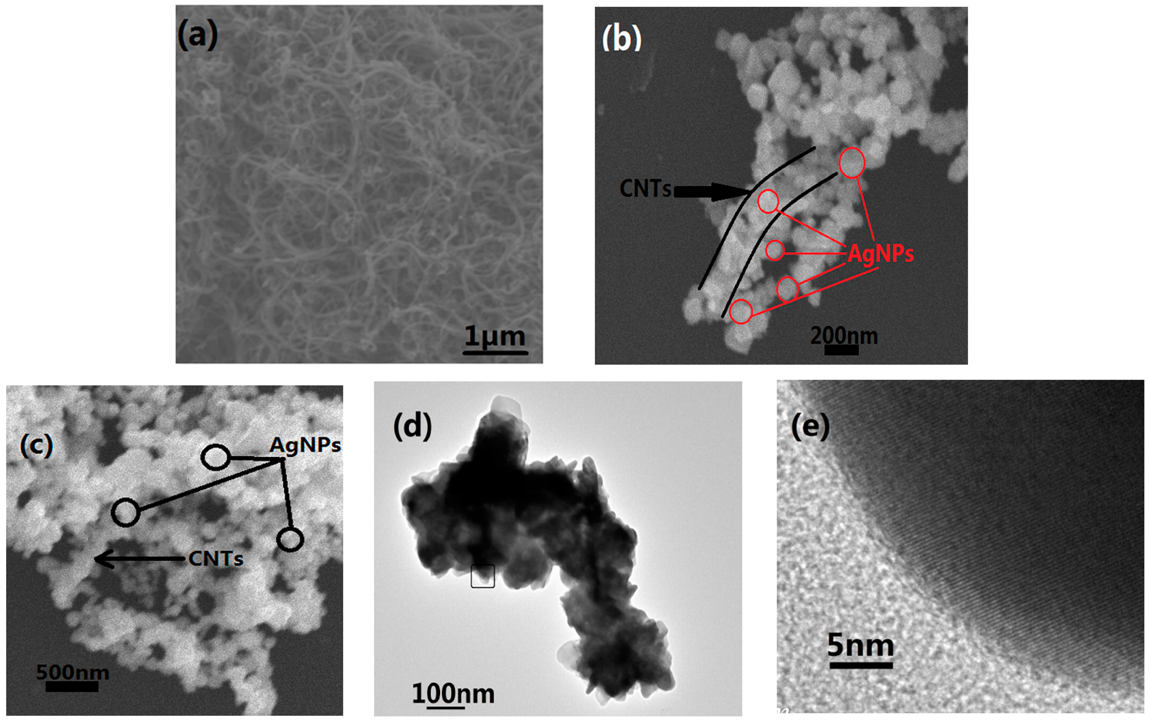
2.1. Synthesis of Ag@CNT Nanocomposites
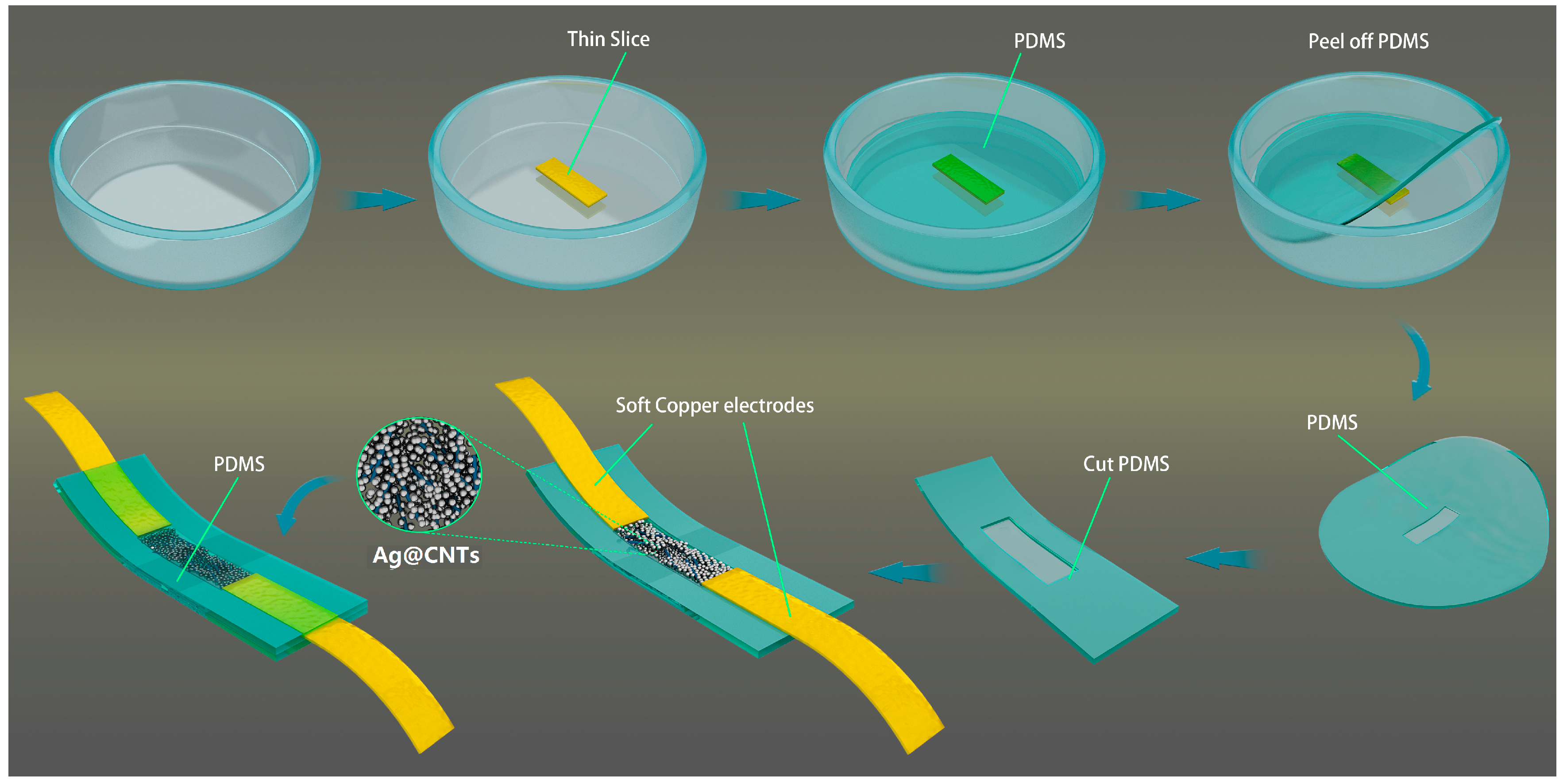
2.2. Preparation of Sensors
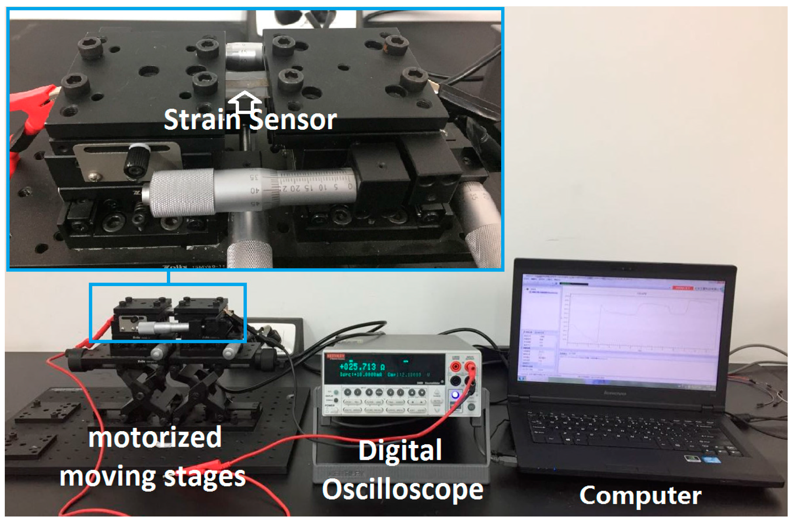
2.3. Sensing Measurement
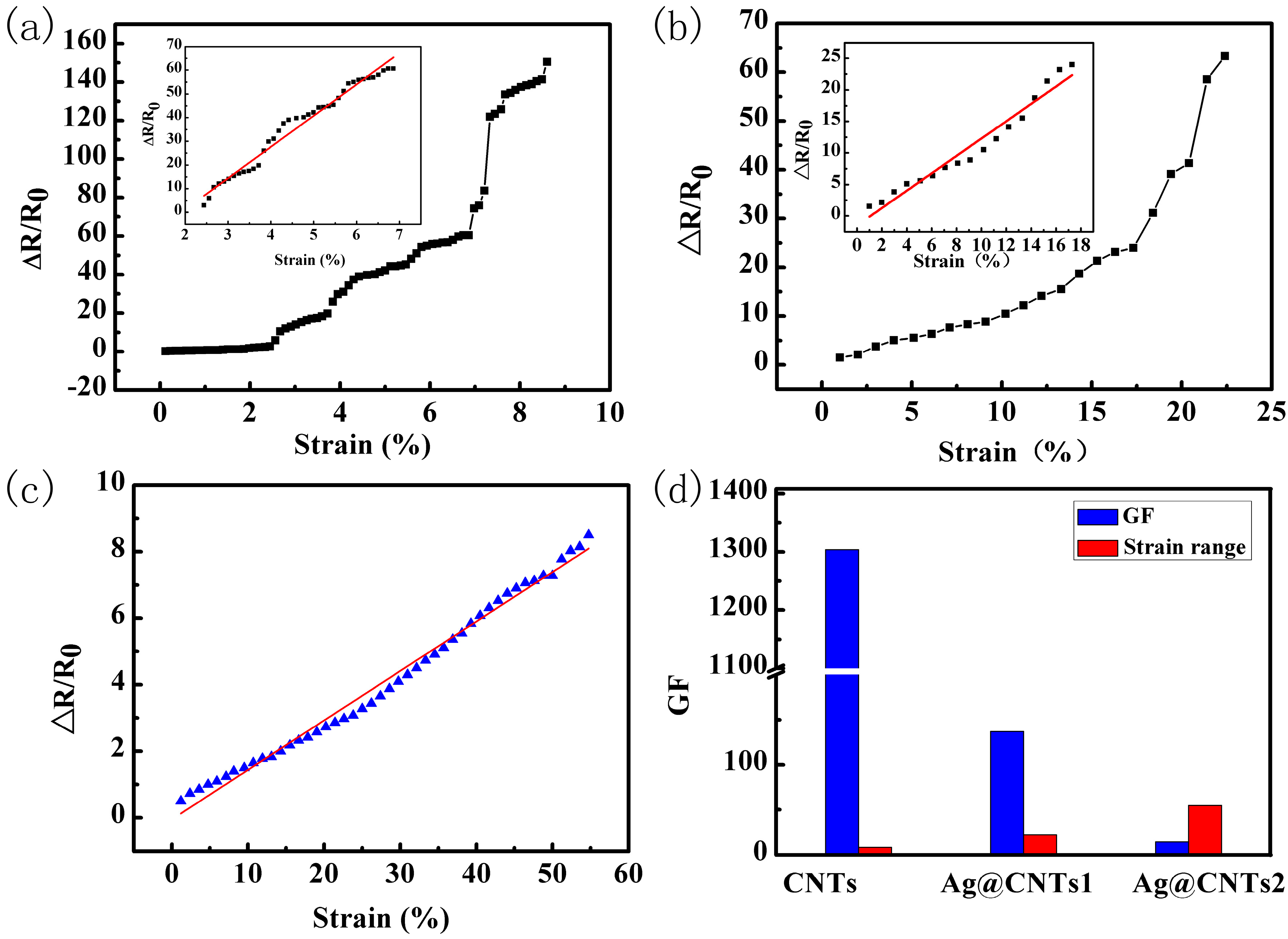
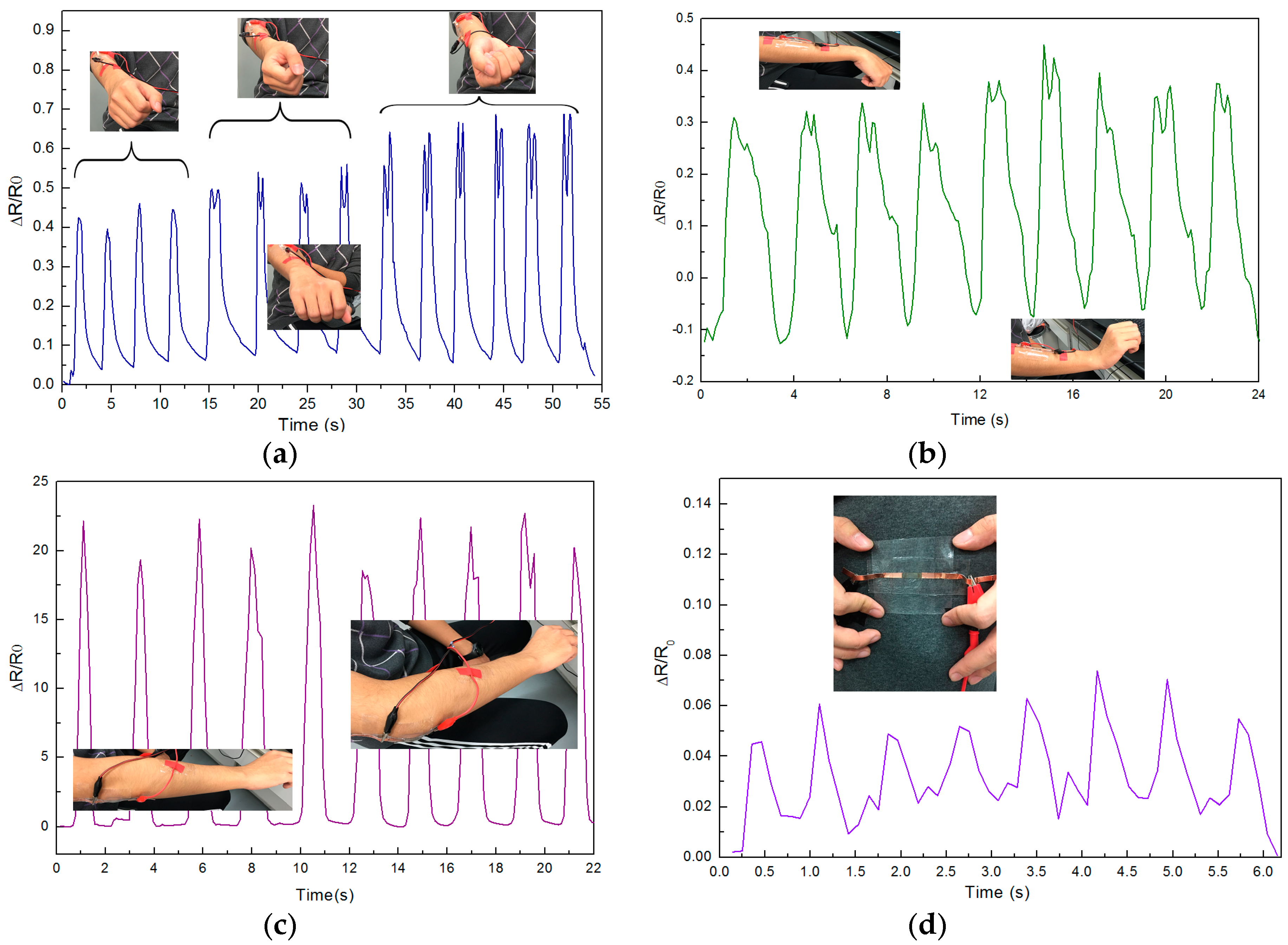
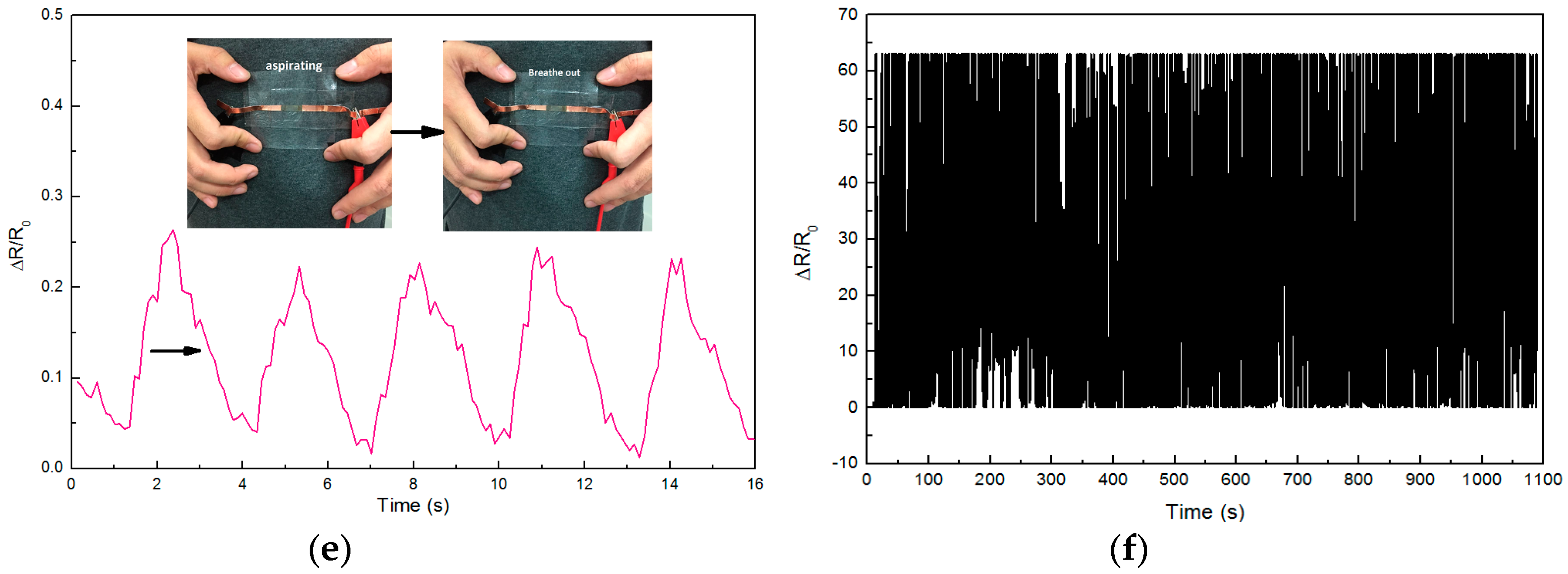
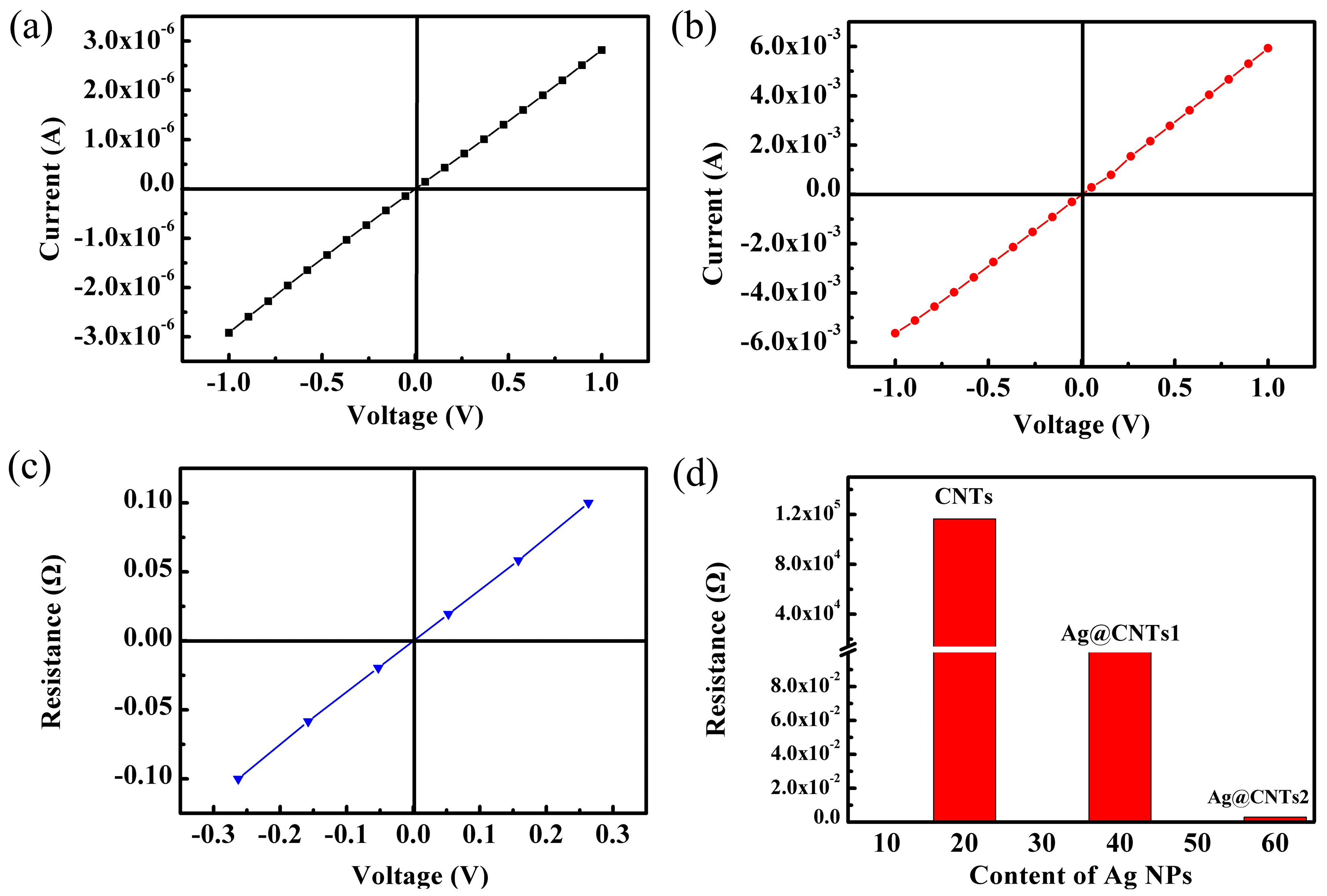
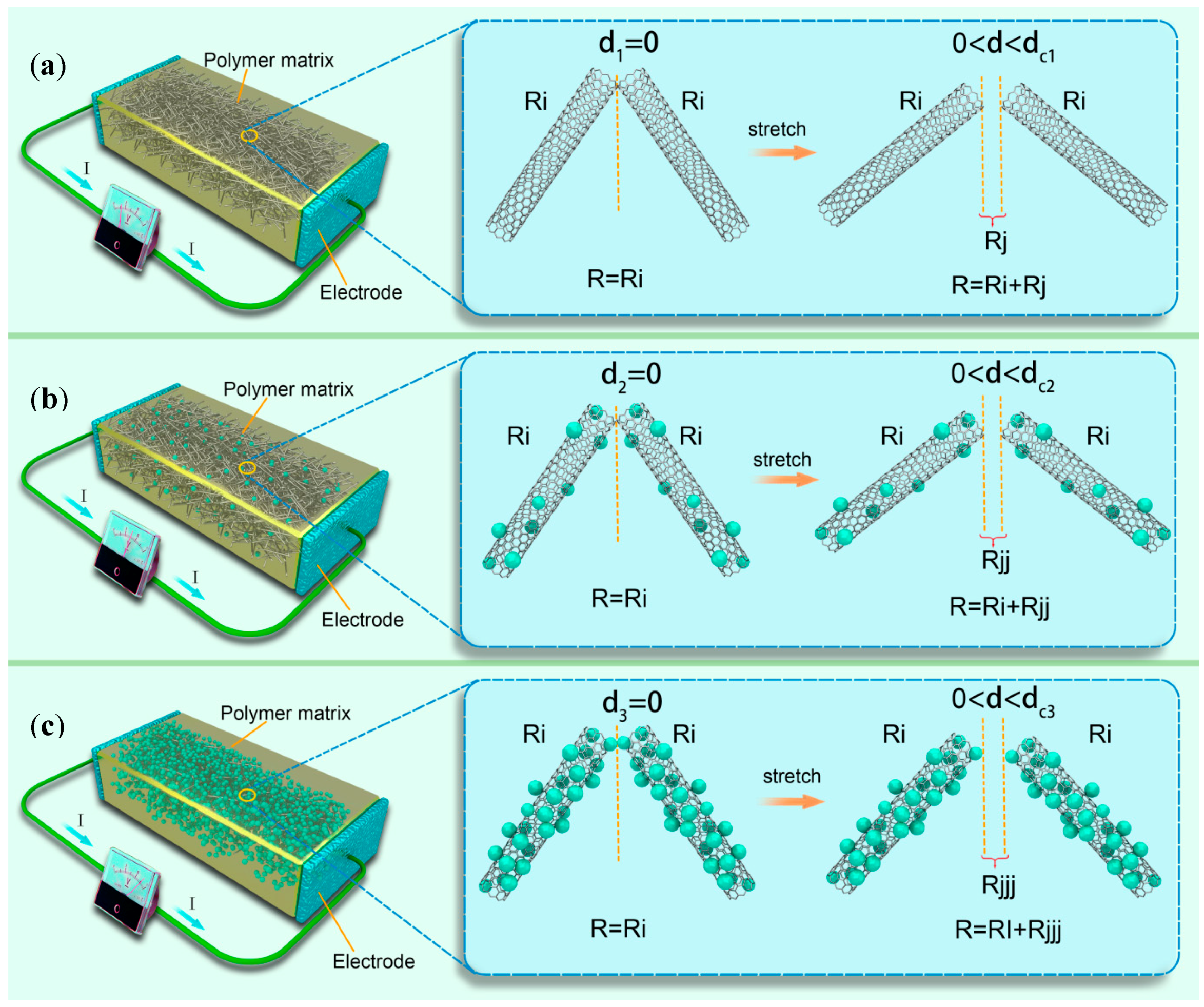
3. Results and Discussion
4. Conclusions
Acknowledgments
Author Contributions
Conflicts of Interest
References
- Matsuzaki, R.; Tabayashi, K. Highly stretchable, global, and distributed local strain sensing line using GaInSn electrodes for wearable electronics. Adv. Funct. Mater. 2015, 25, 3806–3813. [Google Scholar] [CrossRef]
- Hempel, M.; Nezich, D.; Kong, J.; Hofmann, M. A novel class of strain gauges based on layered percolative films of 2D materials. Nano Lett. 2012, 12, 5714–5718. [Google Scholar] [CrossRef] [PubMed]
- Park, M.; Park, J.; Jeong, U. Design of conductive composite elastomers for stretchable electronics. Nano Today 2014, 9, 244–260. [Google Scholar] [CrossRef]
- Liu, C.; Teng, J.; Wu, N. A Wireless Strain Sensor Network for Structural Health Monitoring. Shock Vib. 2015, 2015, 740471. [Google Scholar] [CrossRef]
- Trichias, K.; Pijpers, R.; Meeuwissen, E. A new approach for structural health monitoring by applying anomaly detection on strain sensor data. In Proceedings of the SPIE Smart Structures and Materials+ Nondestructive Evaluation and Health Monitoring, San Diego, CA, USA, 10–14 March2014. [Google Scholar]
- Lim, G.H.; Lee, N.E.; Lim, B. Highly sensitive, tunable, and durable gold nanosheet strain sensors for human motion detection. J. Mater. Chem. C 2016, 4, 5642–5647. [Google Scholar] [CrossRef]
- Cai, L.; Song, L.; Luan, P.; Zhang, Q.; Zhang, N.; Gao, Q.; Zhao, D.; Zhang, X.; Tu, M.; Yang, F.; et al. Super-stretchable, transparent carbon nanotube-based capacitive strain sensors for human motion detection. Sci. Rep. 2013, 3, 3048. [Google Scholar] [CrossRef] [PubMed]
- Yamada, T.; Hayamizu, Y.; Yamamoto, Y.; Yomogida, Y.; Izadi-Najafabadi, A.; Futaba, D.N.; Hata, K. A stretchable carbon nanotube strain sensor for human-motion detection. Nat. Nanotechnol. 2011, 6, 296–301. [Google Scholar] [CrossRef] [PubMed]
- Shi, J.; Li, X.; Cheng, H.; Liu, Z.; Zhao, L.; Yang, T.; Dai, Z.; Cheng, Z.; Shi, E.; Yang, L.; et al. Graphene Reinforced Carbon Nanotube Networks for Wearable Strain Sensors. Adv. Funct. Mater. 2016, 26, 2078–2084. [Google Scholar] [CrossRef]
- Windmiller, J.R.; Wang, J. Wearable electrochemical sensors and biosensors: A review. Electroanalysis 2013, 25, 29–46. [Google Scholar] [CrossRef]
- Webb, R.C.; Bonifas, A.P.; Behnaz, A.; Zhang, Y.; Yu, K.J.; Cheng, H.; Shi, M.; Bian, Z.; Liu, Z.; Kim, Y.S.; et al. Ultrathin conformal devices for precise and continuous thermal characterization of human skin. Nat. Mater. 2013, 12, 938–944. [Google Scholar] [CrossRef] [PubMed]
- Wang, X.; Gu, Y.; Xiong, Z.; Cui, Z.; Zhang, T. Silk-molded flexible, ultrasensitive, and highly stable electronic skin for monitoring human physiological signals. Adv. Mater. 2014, 26, 1336–1342. [Google Scholar] [CrossRef] [PubMed]
- Zeng, W.; Shu, L.; Li, Q.; Chen, S.; Wang, F.; Tao, X. Fiber-based wearable electronics: a review of materials, fabrication, devices, and applications. Adv. Mater. 2014, 26, 5310–5336. [Google Scholar] [CrossRef] [PubMed]
- Amjadi, M.; Pichitpajongkit, A.; Lee, S.; Ryu, S.; Park, I. Highly stretchable and sensitive strain sensor based on silver nanowire-elastomer nanocomposite. ACS Nano 2014, 8, 5154–5163. [Google Scholar] [CrossRef] [PubMed]
- Choi, G.R.; Park, H.K.; Huh, H.; Kim, Y.; Ham, H.; Kim, H.W.; Lim, K.T.; Kim, S.Y.; Kang, I. Strain Sensing Characteristics of Rubbery Carbon Nanotube Composite for Flexible Sensors. J. Nanosci. Nanotechnol. 2014, 16, 1607–1611. [Google Scholar] [CrossRef]
- Zhang, S.; Zhang, H.; Yao, G.; Liao, F.; Gao, M.; Huang, Z.; Li, K.; Lin, Y. Highly stretchable, sensitive, and flexible strain sensors based on silver nanoparticles/carbon nanotubes composites. J. Alloys Compd. 2015, 652, 48–54. [Google Scholar] [CrossRef]
- Sun, P.; Bachilo, S.M.; Weisman, R.B.; Nagarajaiah, S. Carbon nanotubes as non-contact optical strain sensors in smart skins. J. Strain Anal. Eng. 2015, 50, 505–512. [Google Scholar] [CrossRef]
- Li, A.; Bogdanovich, A.E.; Bradford, P.D. Aligned carbon nanotube sheet piezoresistive strain sensors. Smart Mater. Struct. 2015, 24, 095004. [Google Scholar] [CrossRef]
- Dai, H.; Thostenson, E.T.; Schumacher, T. Processing and Characterization of a novel distributed strain sensor using carbon nanotube-based nonwoven composites. Sensors 2015, 15, 17728–17747. [Google Scholar] [CrossRef] [PubMed]
- Seo, J.; Lee, T.J.; Lim, C.; Lee, S.; Rui, C.; Ann, D.; Lee, S.; Lee, H. A Highly Sensitive and Reliable Strain Sensor Using a Hierarchical 3D and Ordered Network of Carbon Nanotubes. Small 2015, 11, 2990–2994. [Google Scholar] [CrossRef] [PubMed]
- Abot, J.L.; Kiyono, C.Y.; Thomas, G.P.; Silva, E.C. Strain gauge sensors comprised of carbon nanotube yarn: Parametric numerical analysis of their piezoresistive response. Smart Mater. Struct. 2015, 24, 075018. [Google Scholar] [CrossRef]
- Zhao, S.; Gao, Y.; Zhang, G.; Deng, L.; Li, J.; Sun, R.; Wong, C.P. Covalently bonded nitrogen-doped carbon-nanotube-supported Ag hybrid sponges: Synthesis, structure manipulation, and its application for flexible conductors and strain-gauge sensors. Carbon 2015, 86, 225–234. [Google Scholar] [CrossRef]
- Lee, B.M.; Wang, L.; Loh, K.J. Characterization of Carbon Nanotube Strain Sensors Using Experimental Tests and Percolation Modeling. In Proceedings of the Tenth International Workshop on Structural Health Monitoring, Stanford, CA, USA, 1–3 September 2015. [Google Scholar]
- Zhao, S.; Zhang, G.; Gao, Y.; Deng, L.; Li, J.; Sun, R.; Wong, C.P. Strain-driven and ultrasensitive resistive sensor/switch based on conductive alginate/nitrogen-doped carbon-nanotube-supported Ag hybrid aerogels with pyramid design. ACS Appl. Mater. Interfaces 2014, 6, 22823–22829. [Google Scholar] [CrossRef] [PubMed]
- Takei, K.; Yu, Z.; Zheng, M.; Ota, H.; Takahashi, T.; Javey, A. Highly sensitive electronic whiskers based on patterned carbon nanotube and silver nanoparticle composite films. Proc. Natl. Acad. Sci. USA 2014, 111, 1703–1707. [Google Scholar] [CrossRef] [PubMed]
- Tran, H.P.; Salazar, N.; Porkka, T.N.; Joshi, K.; Liu, T.; Dickens, T.J.; Yu, Z. Engineering Crack Formation in Carbon Nanotube-Silver Nanoparticle Composite Films for Sensitive and Durable Piezoresistive Sensors. Nanoscale Res. Lett. 2016, 11, 422. [Google Scholar] [CrossRef] [PubMed]
- Zhu, Y.; Qin, Q.; Xu, F.; Fan, F.; Ding, Y.; Zhang, T.; Benjamin, J.W.; Zhong, L.W. Size effects on elasticity, yielding, and fracture of silver nanowires: In situ experiments. Phys. Rev. B 2012, 85, 045443. [Google Scholar] [CrossRef]
- Xu, S.; Rezvanian, O.; Peters, K.; Zikry, M.A. The viability and limitations of percolation theory in modeling the electrical behavior of carbon nanotube-polymer composites. Nanotechnology 2013, 24, 155706. [Google Scholar] [CrossRef] [PubMed]
- Lubineau, G.; Mora, A.; Han, F.; Odeh, I.N.; Yaldiz, R. A morphological investigation of conductive networks in polymers loaded with carbon nanotubes. Comput. Mater. Sci. 2017, 130, 21–38. [Google Scholar] [CrossRef]


| Reference | Materials | Highest GF | Strain Range |
|---|---|---|---|
| [14] | Silver/PDMS | 4.5 | 0–55% |
| [9] | CNTs& Graphene/PDMS | 11.4 | 0–9% |
| [19] | CNTs/Nonwoven | 5.34 | 0–1.8% |
| [22] | N-CNT/Ag sponges | 1.5 | 40% |
| [24] | N-CNTs/Agaerogel monoliths | 15 | 0–60% |
| [25] | Ag&CNTs/PDMS | 20 | 0–2% |
| This work | Ag@CNTs/PDMS | 137.6 | 0–54.8% |
© 2017 by the authors. Licensee MDPI, Basel, Switzerland. This article is an open access article distributed under the terms and conditions of the Creative Commons Attribution (CC BY) license (http://creativecommons.org/licenses/by/4.0/).
Share and Cite
Zhang, Q.; Liu, L.; Zhao, D.; Duan, Q.; Ji, J.; Jian, A.; Zhang, W.; Sang, S. Highly Sensitive and Stretchable Strain Sensor Based on Ag@CNTs. Nanomaterials 2017, 7, 424. https://doi.org/10.3390/nano7120424
Zhang Q, Liu L, Zhao D, Duan Q, Ji J, Jian A, Zhang W, Sang S. Highly Sensitive and Stretchable Strain Sensor Based on Ag@CNTs. Nanomaterials. 2017; 7(12):424. https://doi.org/10.3390/nano7120424
Chicago/Turabian StyleZhang, Qiang, Lihua Liu, Dong Zhao, Qianqian Duan, Jianlong Ji, Aoqun Jian, Wendong Zhang, and Shengbo Sang. 2017. "Highly Sensitive and Stretchable Strain Sensor Based on Ag@CNTs" Nanomaterials 7, no. 12: 424. https://doi.org/10.3390/nano7120424
APA StyleZhang, Q., Liu, L., Zhao, D., Duan, Q., Ji, J., Jian, A., Zhang, W., & Sang, S. (2017). Highly Sensitive and Stretchable Strain Sensor Based on Ag@CNTs. Nanomaterials, 7(12), 424. https://doi.org/10.3390/nano7120424