
A Bifunctional Nanostructured RuPt/C Electrocatalyst for Energy Storage Based on the Chlor-Alkali Process

 , ,
, ,  ,
,  and
and 
Abstract
1. Introduction
2. Materials and Methods
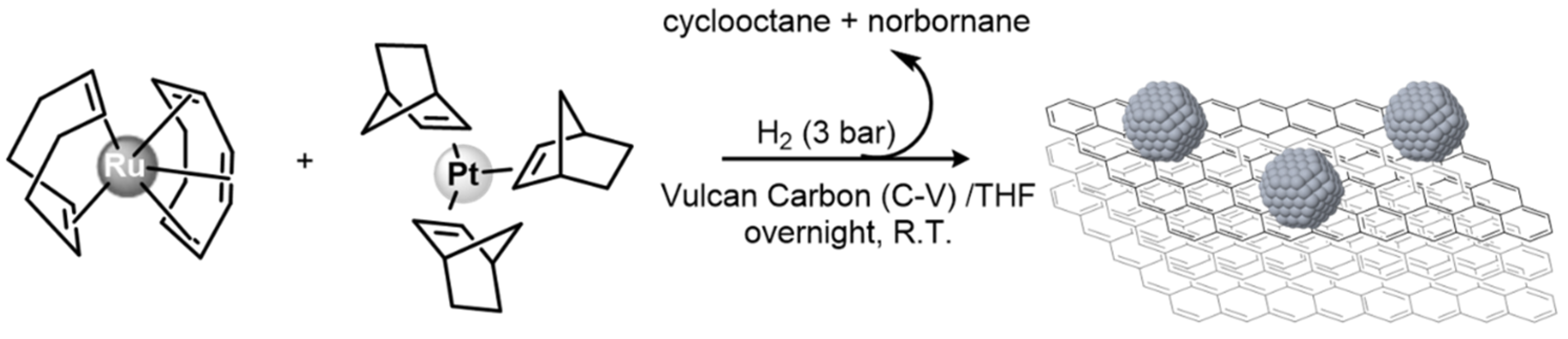
2.1. Synthetic Procedure
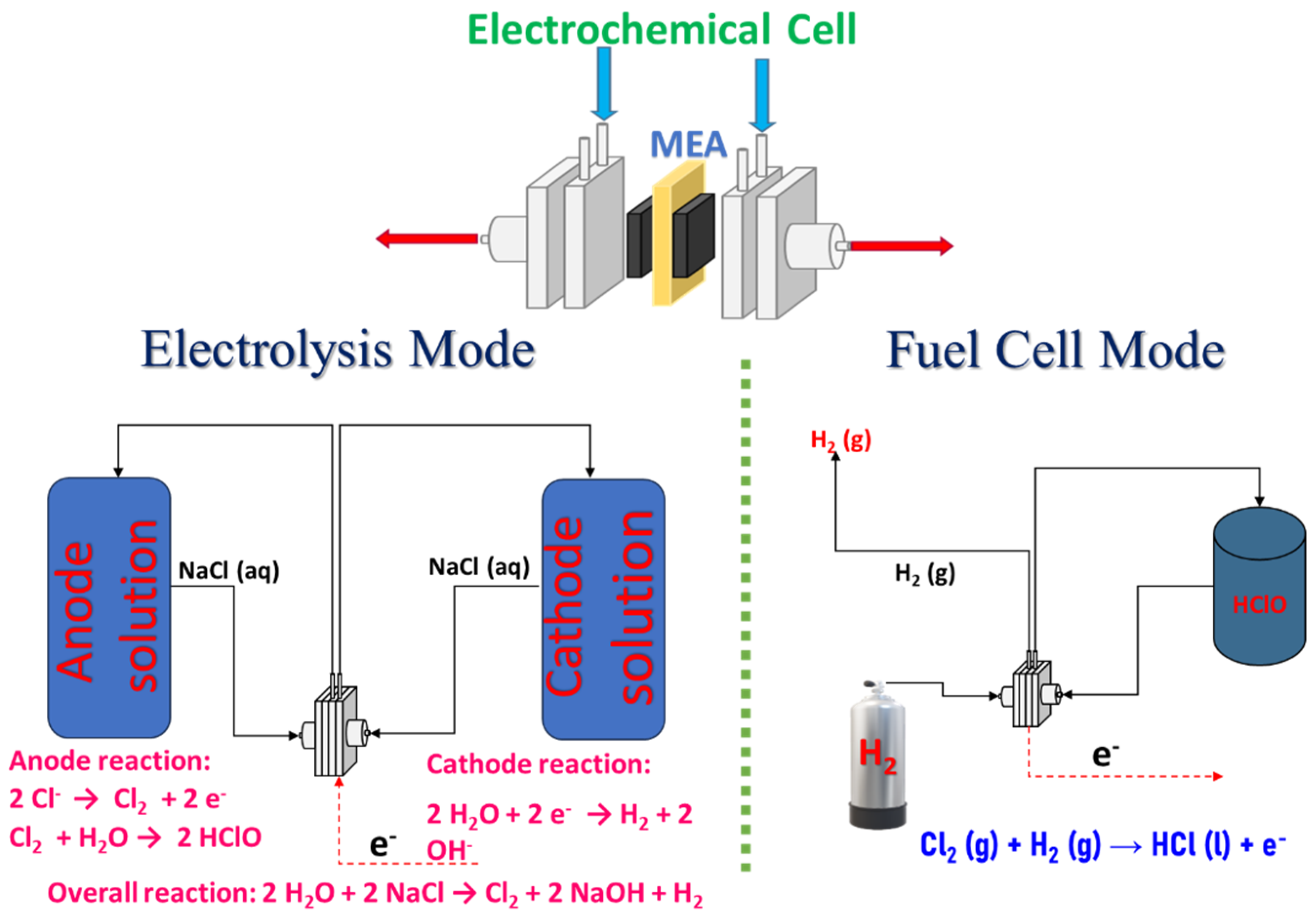
2.2. Electrochemical Cell Design
2.3. Characterization
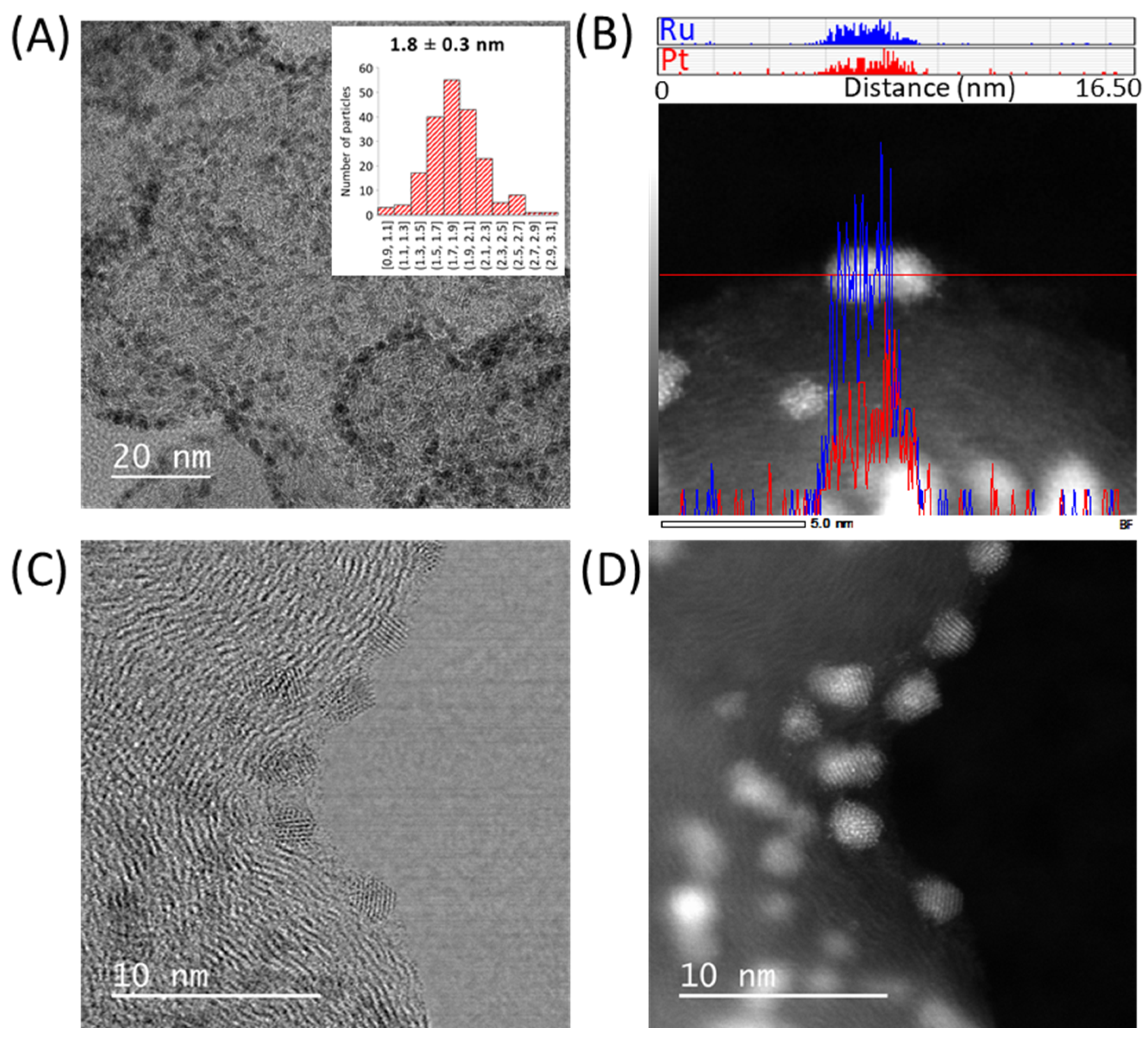
2.3.1. Electron Microscopy Analysis
2.3.2. ICP-OES
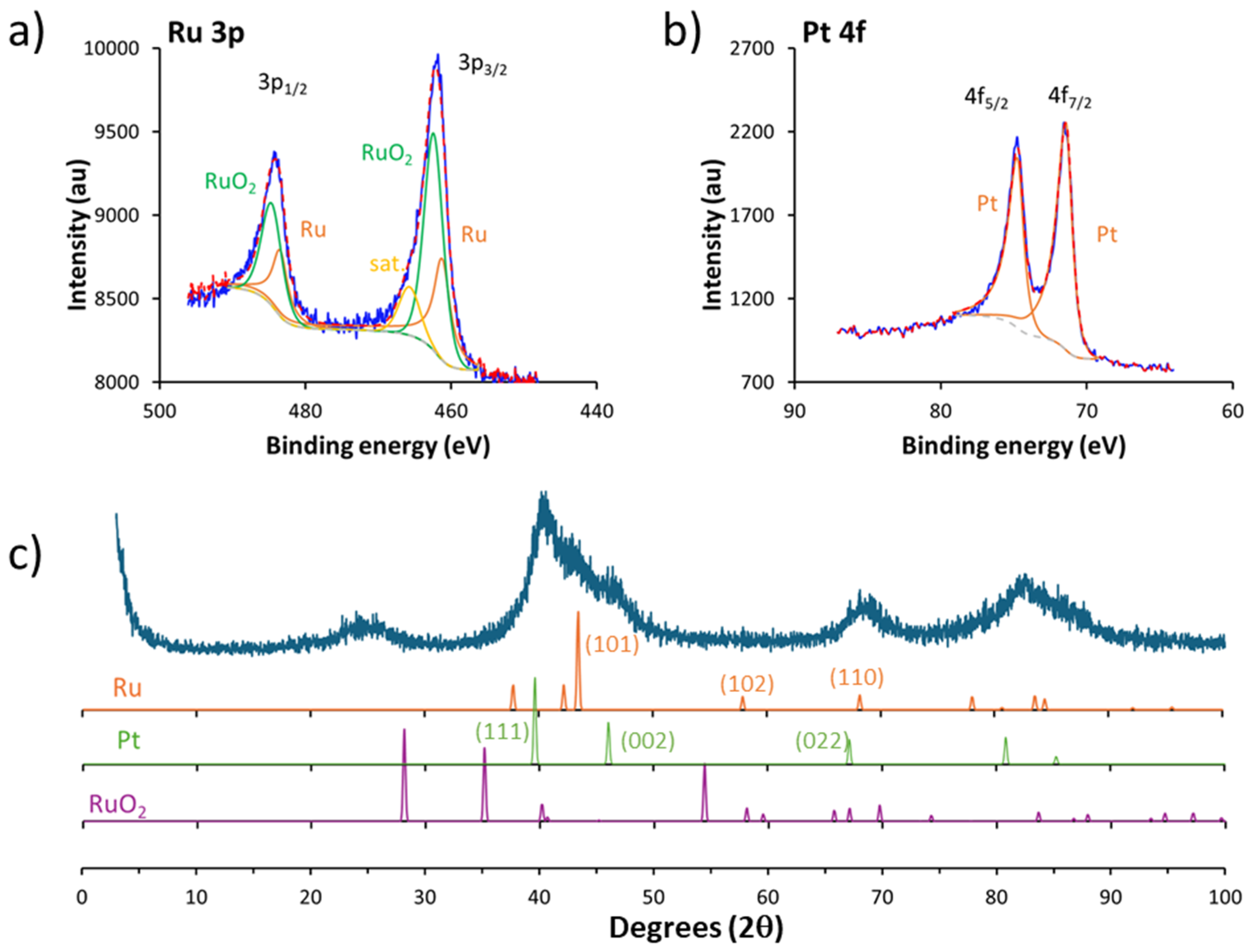
2.3.3. XPS
2.3.4. XRD
3. Results and Discussion
3.1. Synthesis and Characterization of the Materials
3.2. Electrochemical Performance
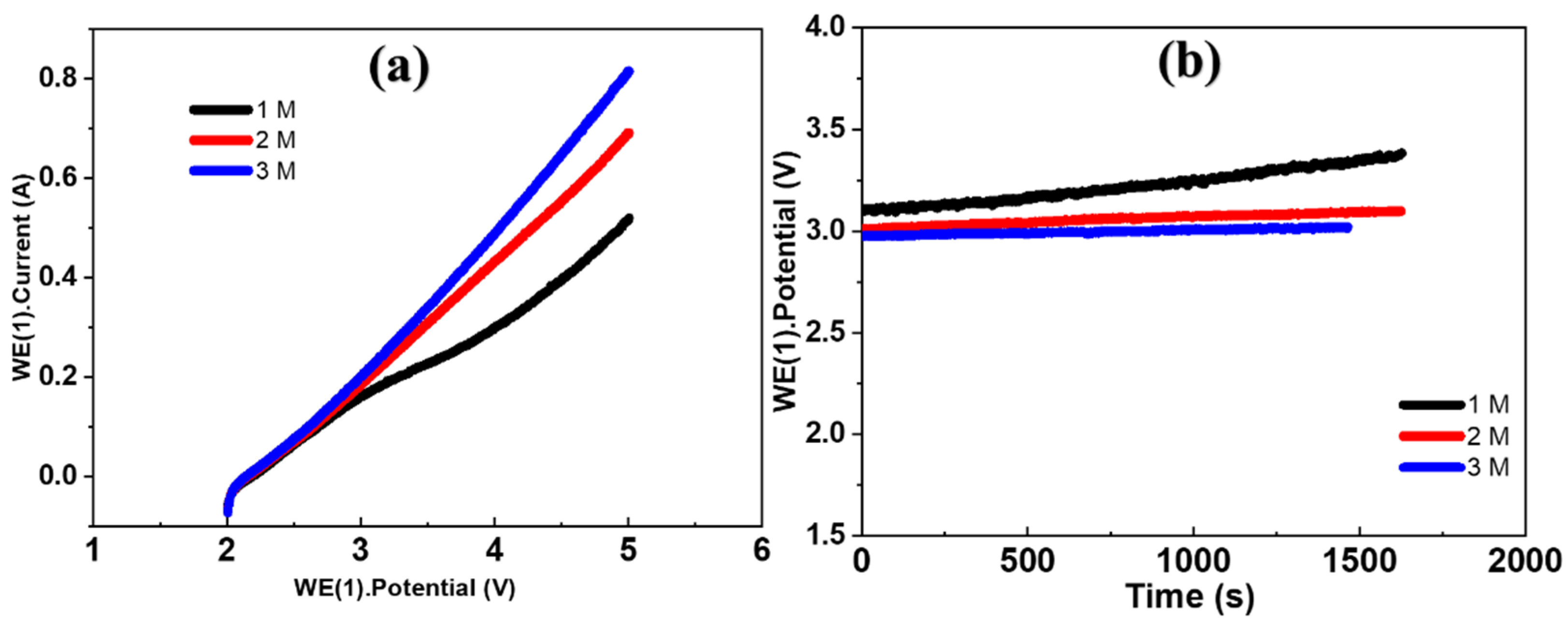
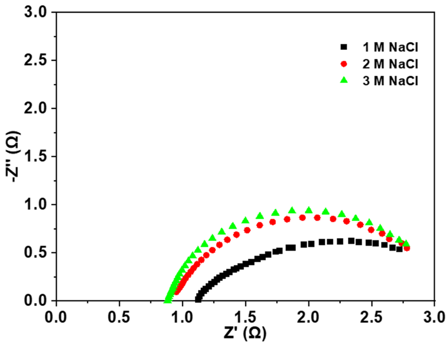
3.2.1. Electrolysis Mode
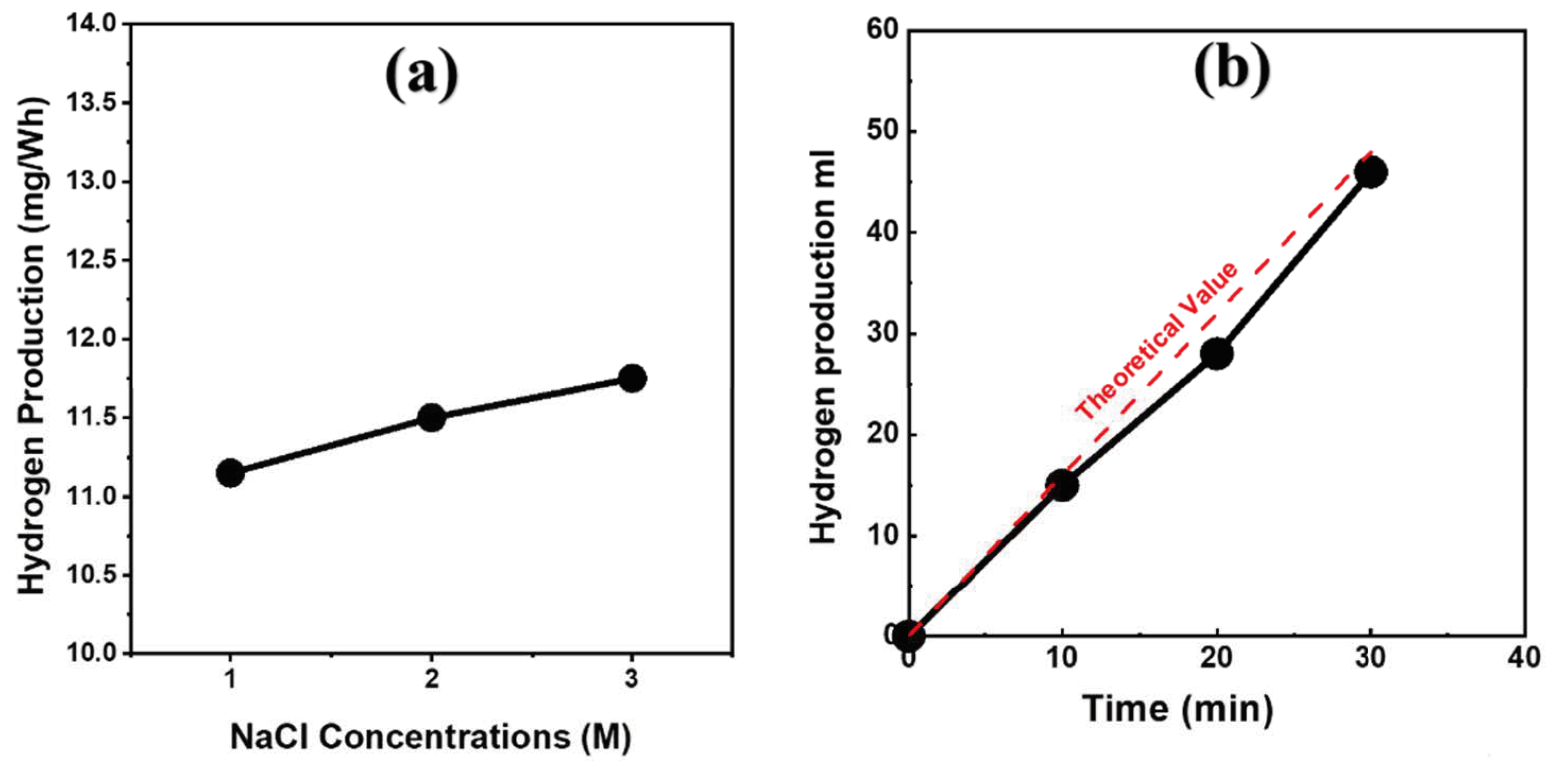
3.2.2. Hydrogen Production
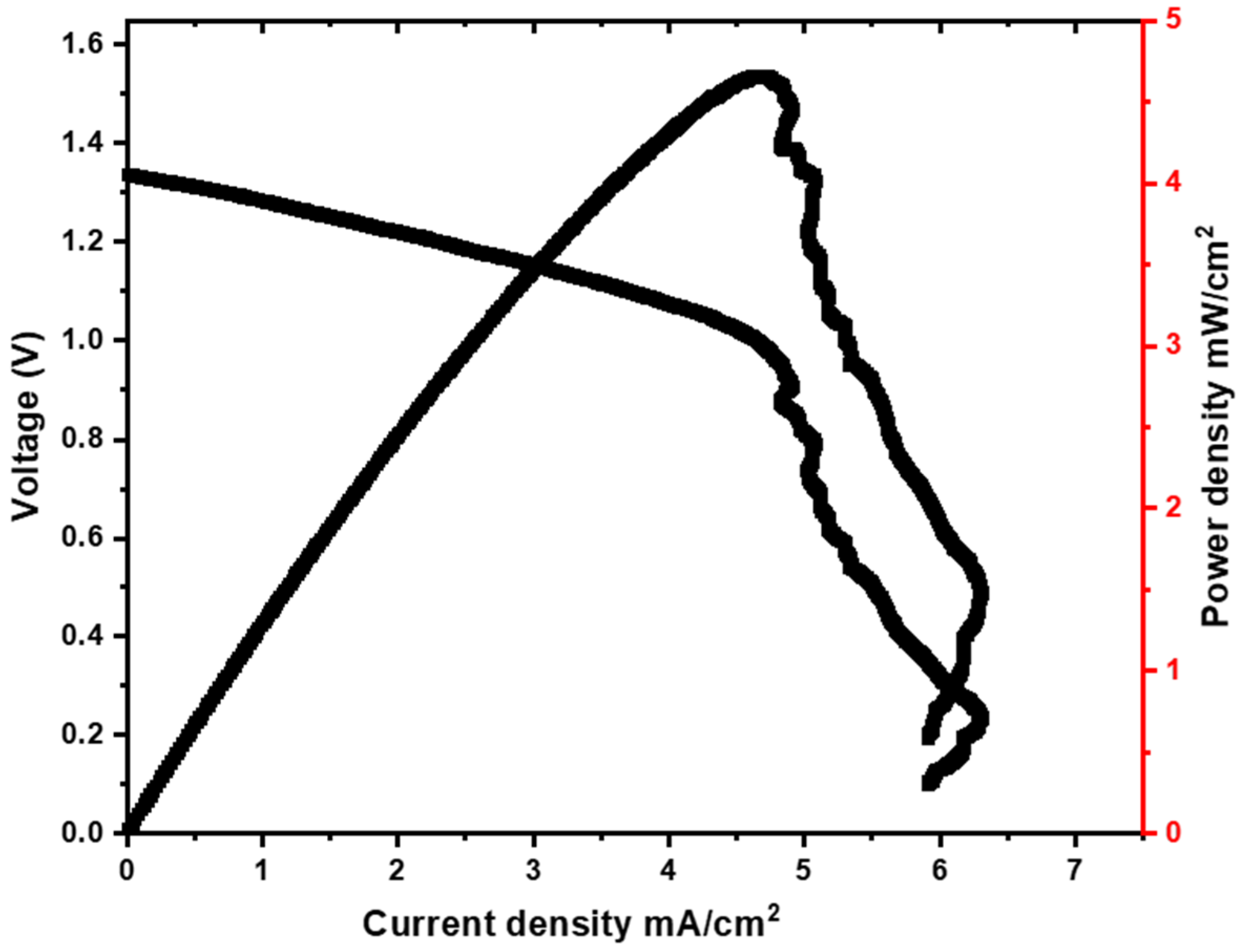
3.2.3. Fuel-Cell Mode
4. Conclusions
Supplementary Materials
Author Contributions
Funding
Data Availability Statement
Acknowledgments
Conflicts of Interest
References
- World Energy Outlook 2024—Analysis. Available online: https://www.iea.org/reports/world-energy-outlook-2024 (accessed on 20 January 2025).
- Detz, R.J.; Reek, J.N.H.; Zwaan, B.C.C. van der The Future of Solar Fuels: When Could They Become Competitive? Energy Environ. Sci. 2018, 11, 1653–1669. [Google Scholar] [CrossRef]
- Hota, P.; Das, A.; Maiti, D.K. A Short Review on Generation of Green Fuel Hydrogen Through Water Splitting. Int. J. Hydrogen Energy 2023, 48, 523–541. [Google Scholar] [CrossRef]
- Abdin, Z.; Khafaf, N.A.; McGrath, B.; Catchpole, K.; Gray, E. A Review of Renewable Hydrogen Hybrid Energy Systems Towards a Sustainable Energy Value Chain. Sustain. Energy Fuels 2023, 7, 2042–2062. [Google Scholar] [CrossRef]
- Yu, J.; Li, Z.; Liu, T.; Zhao, S.; Guan, D.; Chen, D.; Shao, Z.; Ni, M. Morphology Control and Electronic Tailoring of CoxAy (A = P, S, Se) Electrocatalysts for Water Splitting. Chem. Eng. J. 2023, 460, 141674. [Google Scholar] [CrossRef]
- Sapountzi, F.M.; Gracia, J.M.; Fredriksson, H.O.; Niemantsverdriet, J.H. Electrocatalysts for the Generation of Hydrogen, Oxygen and Synthesis Gas. Prog. Energy Combust. Sci. 2017, 58, 1–35. [Google Scholar] [CrossRef]
- Astruc, D. Transition-Metal Nanoparticles in Catalysis: From Historical Background to the State-of-the Art. In Nanoparticles and Catalysis; John Wiley & Sons, Ltd.: Hoboken, NJ, USA, 2007; pp. 1–48. ISBN 978-3-527-62132-3. [Google Scholar]
- Jin, R.; Zeng, C.; Zhou, M.; Chen, Y. Atomically Precise Colloidal Metal Nanoclusters and Nanoparticles: Fundamentals and Opportunities. Chem. Rev. 2016, 116, 10346–10413. [Google Scholar] [CrossRef]
- Eker, F.; Duman, H.; Akdaşçi, E.; Bolat, E.; Sarıtaş, S.; Karav, S.; Witkowska, A.M. A Comprehensive Review of Nanoparticles: From Classification to Application and Toxicity. Molecules 2024, 29, 3482. [Google Scholar] [CrossRef] [PubMed]
- Paras; Yadav, K.; Kumar, P.; Teja, D.R.; Chakraborty, S.; Chakraborty, M.; Mohapatra, S.S.; Sahoo, A.; Chou, M.M.C.; Liang, C.-T.; et al. A Review on Low-Dimensional Nanomaterials: Nanofabrication, Characterization and Applications. Nanomaterials 2023, 13, 160. [Google Scholar] [CrossRef]
- Jin, R.; Pei, Y.; Tsukuda, T. Controlling Nanoparticles with Atomic Precision. Acc. Chem. Res. 2019, 52, 1. [Google Scholar] [CrossRef]
- Core/Shell Nanoparticles: Classes, Properties, Synthesis Mechanisms, Characterization, and Applications | Chemical Reviews. Available online: https://pubs-acs-org.gorgone.univ-toulouse.fr/doi/10.1021/cr100449n (accessed on 20 February 2025).
- Ferrando, R.; Jellinek, J.; Johnston, R.L. Nanoalloys: From Theory to Applications of Alloy Clusters and Nanoparticles. Chem. Rev. 2008, 108, 845–910. [Google Scholar] [CrossRef]
- Li, L.; Zhang, G.; Wang, B.; Yang, T.; Yang, S. Electrochemical Formation of PtRu Bimetallic Nanoparticles for Highly Efficient and pH-Universal Hydrogen Evolution Reaction. J. Mater. Chem. A 2020, 8, 2090–2098. [Google Scholar] [CrossRef]
- Pu, Z.; Amiinu, I.S.; Kou, Z.; Li, W.; Mu, S. RuP2-Based Catalysts with Platinum-like Activity and Higher Durability for the Hydrogen Evolution Reaction at All pH Values. Angew. Chem. Int. Ed. 2017, 56, 11559–11564. [Google Scholar] [CrossRef]
- Mallón, L.; Navarro-Ruiz, J.; Cerezo-Navarrete, C.; Romero, N.; del Rosal, I.; García-Antón, J.; Bofill, R.; Martínez-Prieto, L.M.; Philippot, K.; Poteau, R.; et al. Effect of Nitrogen and Phosphorus Doping of Reduced Graphene Oxide in the Hydrogen Evolution Catalytic Activity of Supported Ru Nanoparticles. ACS Appl. Mater. Interfaces 2025, 17, 6198–6210. [Google Scholar] [CrossRef]
- Li, W.; Zhang, H.; Zhang, K.; Hu, W.; Cheng, Z.; Chen, H.; Feng, X.; Peng, T.; Kou, Z. Monodispersed Ruthenium Nanoparticles Interfacially Bonded with Defective Nitrogen-and-Phosphorus-Doped Carbon Nanosheets Enable pH-Universal Hydrogen Evolution Reaction. Appl. Catal. B Environ. 2022, 306, 121095. [Google Scholar] [CrossRef]
- Zhang, Q.; Wu, M.; Fang, Y.; Deng, C.; Shen, H.-H.; Tang, Y.; Wang, Y. One-Pot Synthesis of Ultra-Small Pt Nanoparticles-Loaded Nitrogen-Doped Mesoporous Carbon Nanotube for Efficient Catalytic Reaction. Nanomaterials 2023, 13, 2633. [Google Scholar] [CrossRef]
- Sun, X.; Gao, X.; Chen, J.; Wang, X.; Chang, H.; Li, B.; Song, D.; Li, J.; Li, H.; Wang, N. Ultrasmall Ru Nanoparticles Highly Dispersed on Sulfur-Doped Graphene for HER with High Electrocatalytic Performance. ACS Appl. Mater. Interfaces 2020, 12, 48591–48597. [Google Scholar] [CrossRef] [PubMed]
- Xu, S.; Niu, M.; Zhao, G.; Ming, S.; Li, X.; Zhu, Q.; Ding, L.-X.; Kim, M.; Alothman, A.A.; Mushab, M.S.S.; et al. Size Control and Electronic Manipulation of Ru Catalyst over B, N Co-Doped Carbon Network for High-Performance Hydrogen Evolution Reaction. Nano Res. 2023, 16, 6212–6219. [Google Scholar] [CrossRef]
- Pang, L.; Miao, Y.; Bhange, S.N.; Barras, A.; Addad, A.; Roussel, P.; Amin, M.A.; Kurungot, S.; Szunerits, S.; Boukherroub, R. Enhanced Electrocatalytic Activity of PtRu/Nitrogen and Sulphur Co-Doped Crumbled Graphene in Acid and Alkaline Media. J. Colloid Interface Sci. 2021, 590, 154–163. [Google Scholar] [CrossRef] [PubMed]
- Yang, J.; Feng, J.; Cao, Y.; Xiao, Y.; Qiao, L.; An, K.; Yang, J.; Peng, J.; Pan, H.; Cheng, H.-M. Highly Dispersed Ru-Pt Heterogeneous Nanoparticles on Reduced Graphene Oxide for Efficient pH-Universal Hydrogen Evolution. Adv. Funct. Mater. 2024, 34, 2411081. [Google Scholar] [CrossRef]
- Gomaa, M.M.; Requena-Leal, I.; Elsharkawy, M.R.M.; Rodrigo, M.A.; Lobato, J. Eco-Friendly Non-Fluorinated Membranes for Renewable Energy Storage. Int. J. Hydrogen Energy 2024, 90, 328–341. [Google Scholar] [CrossRef]
- Requena-Leal, I.; Carvela, M.; Fernández-Marchante, C.M.; Lobato, J.; Rodrigo, M.A. On the Use of Chlor-Alkali Technology to Power Environmental Electrochemical Treatment Technologies. Curr. Opin. Electrochem. 2024, 45, 101461. [Google Scholar] [CrossRef]
- Li, K.; Li, Y.; Wang, Y.; Ge, J.; Liu, C.; Xing, W. Enhanced Electrocatalytic Performance for the Hydrogen Evolution Reaction Through Surface Enrichment of Platinum Nanoclusters Alloying with Ruthenium in Situ Embedded in Carbon. Energy Environ. Sci. 2018, 11, 1232–1239. [Google Scholar] [CrossRef]
- Wang, Y.; Zhu, B.; Cheng, B.; Macyk, W.; Kuang, P.; Yu, J. Hollow Carbon Sphere-Supported Pt/CoOx Hybrid with Excellent Hydrogen Evolution Activity and Stability in Acidic Environment. Appl. Catal. B Environ. 2022, 314, 121503. [Google Scholar] [CrossRef]
- Fang, W.; Ding, C.; Chen, L.; Zhou, W.; Wang, J.; Huang, K.; Zhu, R.; Wu, J.; Liu, B.; Fang, Q.; et al. Review of Hydrogen Storage Technologies and the Crucial Role of Environmentally Friendly Carriers. Energy Fuels 2024, 38, 13539–13564. [Google Scholar] [CrossRef]
- Bacabe, R.; Dupont, M.; Lecoeur, F.; Donzel, N.; Jones, D.J.; Rozière, J.; Jarrosson, T.; Serein-Spirau, F.; Cavaliere, S.; Niebel, C.; et al. Mitigation Strategy of Organic Redox Mediator Crossover in Chemically Regenerative Redox Fuel Cells. Int. J. Hydrogen Energy 2024, 79, 657–665. [Google Scholar] [CrossRef]
- Forner-Cuenca, A.; Brushett, F.R. Engineering Porous Electrodes for Next-Generation Redox Flow Batteries: Recent Progress and Opportunities. Curr. Opin. Electrochem. 2019, 18, 113–122. [Google Scholar] [CrossRef]
- Lourenssen, K.; Williams, J.; Ahmadpour, F.; Clemmer, R.; Tasnim, S. Vanadium Redox Flow Batteries: A Comprehensive Review. J. Energy Storage 2019, 25, 100844. [Google Scholar] [CrossRef]
- Karlsson, R.K.B.; Cornell, A. Selectivity Between Oxygen and Chlorine Evolution in the Chlor-Alkali and Chlorate Processes. Chem. Rev. 2016, 116, 2982–3028. [Google Scholar] [CrossRef]
- Amiens, C.; Chaudret, B.; Ciuculescu-Pradines, D.; Collière, V.; Fajerwerg, K.; Fau, P.; Kahn, M.; Maisonnat, A.; Soulantica, K.; Philippot, K. Organometallic Approach for the Synthesis of Nanostructures. New J. Chem. 2013, 37, 3374–3401. [Google Scholar] [CrossRef]
- Ribeiro, J.Y.C.; Santos, G.O.S.; Dória, A.R.; Requena, I.; Lanza, M.R.V.; Eguiluz, K.I.B.; Salazar-Banda, G.R.; Lobato, J.; Rodrigo, M.A. Platinum-Modified Mixed Metal Oxide Electrodes for Efficient Chloralkaline-Based Energy Storage. Catalysts 2024, 14, 152. [Google Scholar] [CrossRef]
- Carvela, M.; Lobato, J.; Rodrigo, M.A. Chloralkali Low Temperature PEM Reversible Electrochemical Cells. Electrochim. Acta 2021, 387, 138542. [Google Scholar] [CrossRef]
- Creus, J.; Drouet, S.; Suriñach, S.; Lecante, P.; Collière, V.; Poteau, R.; Philippot, K.; García-Antón, J.; Sala, X. Ligand-Capped Ru Nanoparticles as Efficient Electrocatalyst for the Hydrogen Evolution Reaction. ACS Catal. 2018, 8, 11094–11102. [Google Scholar] [CrossRef]
- Pan, C.; Dassenoy, F.; Casanove, M.-J.; Philippot, K.; Amiens, C.; Lecante, P.; Mosset, A.; Chaudret, B. A New Synthetic Method Toward Bimetallic Ruthenium Platinum Nanoparticles; Composition Induced Structural Changes. J. Phys. Chem. B 1999, 103, 10098–10101. [Google Scholar] [CrossRef]
- Qi, X.; Axet, M.R.; Philippot, K.; Lecante, P.; Serp, P. Seed-Mediated Synthesis of Bimetallic Ruthenium–Platinum Nanoparticles Efficient in Cinnamaldehyde Selective Hydrogenation. Dalton Trans. 2014, 43, 9283–9295. [Google Scholar] [CrossRef]
- Bouzouita, D.; Lippens, G.; Baquero, E.A.; Fazzini, P.F.; Pieters, G.; Coppel, Y.; Lecante, P.; Tricard, S.; Martínez-Prieto, L.M.; Chaudret, B. Tuning the Catalytic Activity and Selectivity of Water-Soluble Bimetallic RuPt Nanoparticles by Modifying Their Surface Metal Distribution. Nanoscale 2019, 11, 16544–16552. [Google Scholar] [CrossRef]
- Cerezo-Navarrete, C.; Mathieu, Y.; Puche, M.; Morales, C.; Concepción, P.; Martínez-Prieto, L.M.; Corma, A. Controlling the Selectivity of Bimetallic Platinum–Ruthenium Nanoparticles Supported on N-Doped Graphene by Adjusting Their Metal Composition. Catal. Sci. Technol. 2021, 11, 494–505. [Google Scholar] [CrossRef]
- Carvela, M.; Conti, J.; Lobato, J.; Scialdone, O.; Rodrigo, M.A. Effect of the Anode Composition on the Performance of Reversible Chlor-Alkali Electro-Absorption Cells. Sep. Purif. Technol. 2020, 248, 117017. [Google Scholar] [CrossRef]
- Morgan, D.J. Resolving Ruthenium: XPS Studies of Common Ruthenium Materials. Surf. Interface Anal. 2015, 47, 1072–1079. [Google Scholar] [CrossRef]
- Kibis, L.S.; Svintsitskiy, D.A.; Stadnichenko, A.I.; Slavinskaya, E.M.; Romanenko, A.V.; Fedorova, E.A.; Stonkus, O.A.; Svetlichnyi, V.A.; Fakhrutdinova, E.D.; Vorokhta, M.; et al. In Situ Probing of Pt/TiO2 Activity in Low-Temperature Ammonia Oxidation. Catal. Sci. Technol. 2021, 11, 250–263. [Google Scholar] [CrossRef]
- Lobato, J.; Cañizares, P.; Ubeda, D.; Pinar, F.J.; Rodrigo, M.A. Testing PtRu/CNF Catalysts for a High Temperature Polybenzimidazole-Based Direct Ethanol Fuel Cell. Effect of Metal Content. Appl. Catal. B Environ. 2011, 106, 174–180. [Google Scholar] [CrossRef]
- Li, J.; Liang, Y.; Liao, Q.; Zhu, X.; Tian, X. Comparison of the Electrocatalytic Performance of PtRu Nanoparticles Supported on Multi-Walled Carbon Nanotubes with Different Lengths and Diameters. Electrochim. Acta 2009, 54, 1277–1285. [Google Scholar] [CrossRef]
- Hsu, S.-Y. Effects of Flow Rate, Temperature and Salt Concentration on Chemical and Physical Properties of Electrolyzed Oxidizing Water. J. Food Eng. 2005, 66, 171–176. [Google Scholar] [CrossRef]
- Zhang, W.; Ma, J.; Wang, P.; Wang, Z.; Shi, F.; Liu, H. Investigations on the Interfacial Capacitance and the Diffusion Boundary Layer Thickness of Ion Exchange Membrane Using Electrochemical Impedance Spectroscopy. J. Membr. Sci. 2016, 502, 37–47. [Google Scholar] [CrossRef]
- Rashidi, M.; Blokhus, A.M.; Skauge, A. Viscosity Study of Salt Tolerant Polymers. J. Appl. Polym. Sci. 2010, 117, 1551–1557. [Google Scholar] [CrossRef]
- Garcia-Herrero, I.; Margallo, M.; Onandía, R.; Aldaco, R.; Irabien, A. Life Cycle Assessment Model for the Chlor-Alkali Process: A Comprehensive Review of Resources and Available Technologies. Sustain. Prod. Consum. 2017, 12, 44–58. [Google Scholar] [CrossRef]
- Garcia-Herrero, I.; Margallo, M.; Onandía, R.; Aldaco, R.; Irabien, Á. Connecting Wastes to Resources for Clean Technologies in the Chlor-Alkali Industry: A Life Cycle Approach. Clean Technol. Environ. Policy 2018, 20, 229–242. [Google Scholar] [CrossRef]
- Selyari, T.; Ghoreyshi, A.A.; Shakeri, M.; Najafpour, G.D.; Jafary, T. Measurement of Polarization Curve and Development of a Unique Semi Empirical Model for Description of PEMFC and DMFC Performances. Chem. Ind. Chem. Eng. Q. 2011, 17, 207–214. [Google Scholar] [CrossRef]
- Bockris, J.O.; Shamshul Huq, A.K.M.; Taylor, H.S. The Mechanism of the Electrolytic Evolution of Oxygen on Platinum. Proc. R. Soc. London. Ser. A. Math. Phys. Sci. 1997, 237, 277–296. [Google Scholar] [CrossRef]
- Xu, Y.; Zhao, Y.; Yuan, Z.; Sun, Y.; Peng, S.; Zhong, Y.; Sun, M.; Yu, L. Balancing the Relationship Between the Activity and Stability of Anode Oxide-Based Electrocatalysts in Acid for PEMWE Electrolyzers. J. Mater. Chem. A 2024, 12, 18751–18773. [Google Scholar] [CrossRef]
- Goryachev, A.; Etzi Coller Pascuzzi, M.; Carlà, F.; Weber, T.; Over, H.; Hensen, E.J.M.; Hofmann, J.P. Electrochemical Stability of RuO2(110)/Ru(0001) Model Electrodes in the Oxygen and Chlorine Evolution Reactions. Electrochim. Acta 2020, 336, 135713. [Google Scholar] [CrossRef]
- Chen, J.; Qi, M.; Yang, Y.; Xiao, X.; Li, Y.; Jin, H.; Wang, Y. Chloride Residues in RuO2 Catalysts Enhance Its Stability and Efficiency for Acidic Oxygen Evolution Reaction. Angew. Chem. 2025, 137, e202420860. [Google Scholar] [CrossRef]
Disclaimer/Publisher’s Note: The statements, opinions and data contained in all publications are solely those of the individual author(s) and contributor(s) and not of MDPI and/or the editor(s). MDPI and/or the editor(s) disclaim responsibility for any injury to people or property resulting from any ideas, methods, instructions or products referred to in the content. |
© 2025 by the authors. Licensee MDPI, Basel, Switzerland. This article is an open access article distributed under the terms and conditions of the Creative Commons Attribution (CC BY) license (https://creativecommons.org/licenses/by/4.0/).
Share and Cite
Romero, N.; Gomaa, M.M.; Esvan, J.; Rodrigo, M.A.; Philippot, K.; Lobato, J. A Bifunctional Nanostructured RuPt/C Electrocatalyst for Energy Storage Based on the Chlor-Alkali Process. Nanomaterials 2025, 15, 506. https://doi.org/10.3390/nano15070506
Romero N, Gomaa MM, Esvan J, Rodrigo MA, Philippot K, Lobato J. A Bifunctional Nanostructured RuPt/C Electrocatalyst for Energy Storage Based on the Chlor-Alkali Process. Nanomaterials. 2025; 15(7):506. https://doi.org/10.3390/nano15070506
Chicago/Turabian StyleRomero, Nuria, Mahmoud M. Gomaa, Jérôme Esvan, Manuel A. Rodrigo, Karine Philippot, and Justo Lobato. 2025. "A Bifunctional Nanostructured RuPt/C Electrocatalyst for Energy Storage Based on the Chlor-Alkali Process" Nanomaterials 15, no. 7: 506. https://doi.org/10.3390/nano15070506
APA StyleRomero, N., Gomaa, M. M., Esvan, J., Rodrigo, M. A., Philippot, K., & Lobato, J. (2025). A Bifunctional Nanostructured RuPt/C Electrocatalyst for Energy Storage Based on the Chlor-Alkali Process. Nanomaterials, 15(7), 506. https://doi.org/10.3390/nano15070506