Abstract
A novel low-carbon 9Cr-ODS steel was exposed to corrosion in lead–bismuth eutectic saturated with oxygen at 500 °C for 1000 h, leading to the formation of three distinct layers of oxide film. From the outermost to the innermost layer, these included a Fe3O4 layer infiltrated with Pb, a FeCr2O4 layer, and an inner oxide zone. The inner oxide zone was primarily composed of an unoxidized matrix and Cr2O3. The formation of the inner oxide zone was primarily attributed to the preferential oxidation of Cr following the infiltration of insufficient O content. Two distinct morphologies of the inner oxide zone were identified: one is porous, while the other is non-porous. The porous morphology is characterized by low Fe content and Pb infiltration. The loss of Fe is the main factor contributing to the development of the porous inner oxide zone and the infiltration of Pb, while the short-range diffusion of Cr promotes the growth of Cr2O3, resulting in a needle-like morphology.
1. Introduction
Energy is a fundamental issue confronting human development. As a form of clean energy, nuclear energy is considered to be one of the key potential solutions to address the energy crisis [1]. Lead-cooled fast reactors (LFRs), a type of fourth-generation nuclear reactor, have garnered significant attention [2]. This interest is primarily attributable to the use of Pb or lead–bismuth eutectic (LBE) as a coolant. The excellent neutron properties of LBE enable an increase in the reactor’s energy density, facilitating its miniaturization and modular design. Furthermore, Pb or LBE could also be used as heavy metal targets for the Accelerator Driven Subcritical System (ADS), which represents an advanced technology for the treatment of nuclear waste within the current nuclear energy sector [3]. Pb and LBE are extensively utilized in nuclear science; thus, issues associated with LBE have been a prominent topic of research in recent years [4]. However, LBE exhibits high solubility with metallic elements, making it highly corrosive to structural materials [5,6]. The structural materials utilized in an LBE environment must withstand a harsh combination of long-term high temperatures, significant radiation damage, strong corrosion, and mechanical stress, all of which pose substantial challenges to the long-term stable operation of the reactor.
Oxide Dispersion Strengthened (ODS) steel is a type of steel known for its excellent radiation resistance [7,8,9,10]. It mitigates radiation-induced defects in the material by dispersing nano-scale Y2O3 particles throughout the steel. Recently, the Institute of Metal Research at the Chinese Academy of Sciences developed a novel low-carbon 9Cr-ODS steel [11,12]. This new material circumvents the formation of the M23C6 phase—a precipitated phase that tends to grow at elevated temperatures and adversely affects the material’s properties—by reducing the carbon content [13,14,15,16]. V and N elements are added to form VN precipitates to compensate for the loss of material strength in reducing M23C6. After a 3000 h, 700 °C high-temperature test, it was found that the comprehensive mechanical properties and microstructure of low-carbon 9Cr-ODS steel remained stable [12]. Xu et al. [17] used 3Mev Fe ion to conduct an experiment at 550 °C under the condition that the irradiation damage reached 70 dpa, and found that the micro-precipitated phase remained stable as a whole. Therefore, low-carbon 9Cr-ODS steel is expected to solve the problem of irradiation and high temperature at the same time. However, its corrosion performance requires further in-depth study.
Currently, one of the primary solutions to the issue of LBE corrosion involves the formation of a protective oxide film [18,19,20]. It is generally observed that when the oxygen partial pressure exceeds 10–6 wt.%, steel containing Fe and Cr will develop a double-layer oxide film [21,22,23]. The inner oxide layer (IOL) typically consists of dense, protective FeCr2O4, while the outer oxide layer (OOL) is usually Fe3O4. Du et al. [24] investigated the corrosion of 9Cr-ODS steel after heat treatment in oxygen-saturated LBE at 600 °C for 500 h, and found that a double-layer oxide film was formed, with the inner oxide layer providing effective protection and showing no infiltration of LBE. Zhu et al. [25] investigated the corrosion of ODS-FeCrAl steel in oxygen-saturated LBE at 550 °C for over 8000 h. They found that a double-layer oxide film was formed, with the IOL playing a significant protective role. In general, IOLs are crucial for enhancing corrosion resistance. Currently, the predominant theory regarding the growth mechanism of the double-layer oxide film formed during LBE corrosion is the available space model [26,27,28]. This model posits that Fe is the primary factor driving the growth of the oxide film. The expansion of the outer Fe3O4 oxide layer results from the outward diffusion of Fe, while the formation of FeCr2O4 in the IOL is attributed to vacancies created by Fe diffusion, which facilitates the inward diffusion of O. However, some experiments have demonstrated that, during the LBE corrosion process, a chromium-rich region, referred to as the internal oxide zone (IOZ), often forms beneath the IOL [29,30,31]. Zhao et al. [32] corroded 9Cr ferritic–martensitic steel in LBE with an oxygen content of 10–6 wt.% at 550 °C for 1750 h, and they discovered the presence of an IOZ in addition to the double-layer oxide film. Yeliseyeva et al. [33] conducted corrosion tests on 316L steel using oxygen-saturated LBE at temperatures exceeding 500 °C for a duration of 1000 h, which formed an obvious IOZ below the oxide film. The formation of an IOZ is commonly observed in long-term corrosion experiments [34]. This phenomenon can be attributed to the fact that, with sufficient corrosion time, the IOL will thicken, effectively reducing the rate of oxygen diffusion into the matrix. At this stage, from a thermodynamic perspective, the O content at the interface between the oxide film and the matrix (O/M) is insufficient to oxidize the iron in the matrix to form FeCr2O4. Instead, it leads to the formation of Cr2O3, which contributes to the development of an IOZ. In this study, we identified two distinct morphologies of IOZs: porous and non-porous, with a particular interest in the former. According to the available space model, the IOZ region is expected to gradually transition into an IOL. The presence of a porous IOZ may ultimately lead to a reduction in the density of the IOL or even to the detachment of the oxide film, thereby compromising the material’s corrosion resistance. Additionally, from the perspective of elemental uniformity, this may result in localized depletion of chromium, adversely affecting the uniformity of the matrix properties. Therefore, we contend that the impact of IOZs on corrosion performance should not be overlooked. In the literature reviewed by the authors, the porous morphology of IOZs resulting from LBE corrosion has not been previously studied; therefore, it is essential to advance the investigation of IOZs further.
In this study, we investigated the corrosion of the oxide film on low-carbon 9Cr-ODS steel in oxygen-saturated LBE at 500 °C for 1000 h. Our findings revealed the presence of an IOZ below the IOL, which was categorized into porous and non-porous morphologies. Both morphologies of the IOZ were meticulously characterized using scanning electron microscopy (SEM) and transmission electron microscopy (TEM), and the mechanisms underlying IOZ formation were elucidated. This research aims to enhance our understanding of the corrosion mechanisms affecting steel in LBE environments.
2. Materials and Methods
2.1. Materials
The low-carbon 9Cr-ODS steel utilized in this experiment was supplied by the Institute of Metal Research, Chinese Academy of Sciences, with the specific production process detailed in previous work [17]. Upon receipt, the sample weighed approximately 1 kg and was in the form of a cuboid block. After being polished to a smooth finish with 400 mesh SiC sandpaper, the dimensions of the cuboid sample were reduced to approximately 3 × 2 × 0.2 cm via wire cutting. Subsequently, all six surfaces were polished to a glossy finish using 400, 600, 1000, and 2000 mesh SiC sandpaper, followed by 1 µm and 0.5 µm alumina polishing liquids. The chemical composition of the matrix elements is presented in Table 1.

Table 1.
Nominal composition of 9Cr-ODS steel used in this study (wt.%).
2.2. Corrosion Test
The corrosion tests were conducted in a tubular furnace under an argon atmosphere with a flow rate of approximately 50 mL/min. The composition of the LBE consisted of 44.5 wt.% Pb and 55.5 wt.% Bi. During the preparation process, 0.013 wt.% PbO and 0.016 wt.% Bi2O3 were added to inhibit the reaction between dissolved oxygen and LBE [17]. Prior to the corrosion test, 400 g of solid LBE was placed in an alumina crucible and heated to 200 °C in a muffle furnace to facilitate melting. The sample was secured on 316L steel wire and subsequently introduced into the crucible. The crucible was then positioned in a tubular furnace, and the LBE was heated to 500 °C for the corrosion experiments. At the conclusion of the experiment, solid yellow oxides (PbO and Bi2O3) were observed floating on the surface of the crucible, while the crucible’s interior contained molten LBE. This phenomenon can be attributed to the lower density and higher melting points of PbO (888 °C) and Bi2O3 (860 °C) when compared to LBE. The formation of PbO and Bi2O3 at 500 °C necessitates high oxygen concentrations of 10−4 wt.% and 10−3 wt.%, respectively, which exceed the oxygen saturation level of LBE (approximately 10−3 wt.%). Thus, it can be inferred that the experiment achieved oxygen-saturated conditions. After the corrosion test, the sample was removed and allowed to cool to room temperature. The sample was then cold-set using epoxy resin and coagulant. The corroded section was polished using 400, 600, 1000, and 2000 mesh SiC sandpaper, followed by 1 µm and 0.5 µm alumina polishing liquid, until a smooth, mirror-like finish was achieved.
2.3. Microstructure Characterization
After the corrosion experiments, we employed SEM and TEM to analyze the oxide film resulting from corrosion. A gold coating was applied to the cross-section of the sample to enhance its electrical conductivity. MC1000 gold spraying equipment from Hitachi, Tokyo, Japan, was utilized, which includes the MC1000 main unit, an HHTNT-CT-2000 transformer, a gold target material, and a Hitachi vacuum pump. Subsequently, microstructural and elemental analyses were conducted using a scanning electron microscope (SEM, Gemini 500, ZEISS Sigma, Cambridge, UK) and an energy dispersive spectrometer (EDS). The TEM specimen was prepared by the SEM microscope equipped with a Ga-focused ion beam (FIB, 30 kV, Thermo Scientific Scios 2, Thermo Fisher Scientific, Waltham, MA, USA) and an Omniprobe manipulator. The pieces were initially pre-cut from the bulk samples by using a current of 7 nA, and then ion beam currents from 0.5, 0.3, and 0.1 nA to 10 pA were used in sequence to further mill the piece into electron-transparent slices with a thickness of 70 nm [24]. The microstructure of the samples was characterized by TEM (Talos 200 kv, Thermo Fisher Scientific, Waltham, MA, USA and JL-F200, JEOL, Tokyo, Japan).
3. Results
Figure 1 shows the cross-sectional morphology of the oxide film and the EDS results obtained via SEM following corrosion. The image was captured using the BSE mode, where the brighter areas correspond to regions rich in heavy elements, particularly LBE. As depicted in Figure 1a, a uniform oxide film approximately 25 μm thick formed on the substrate surface after corrosion. The magnified view of the yellow region is presented in Figure 1b. Integrating the EDS results from Figure 1c,d, we observe that the oxide film is stratified into three distinct layers. The OOL appears porous, exhibiting numerous gray spots, and energy spectrum analysis indicates it is infiltrated with LBE and primarily composed of Fe and O. The inner oxide layer (IOL) demonstrates robust overall protection, with energy spectrum results showing it mainly contains Cr, Mn, O, and Fe, while fluctuations in the Pb peak within the IOL are also noted. Notably, we identified an inner oxidation zone (IOZ) rich in Cr and O located beneath the IOL. The IOZ exhibits two predominant morphologies: one is porous, and the other is non-porous. Figure 1d reveals that the IOZ region is enriched with Cr, Mn, and O but poor in Fe, with a corresponding increase in Pb. We are particularly interested in the morphology variations within the IOZ region.
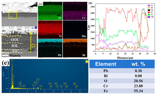
Figure 1.
Cross-sectional SEM results of the sample after 1000 h of corrosion at 500 °C: (a) morphology in backscattered electron (BSE) mode; (b) magnification corresponding to the yellow box in (a); (c) EDS mappings of Fe, Cr, Mn, O, Pb, and Bi corresponding to (b); (d) EDS line scan of Fe, Cr, Mn, O, Pb, and Bi along the yellow arrow in (b); (e) Point energy spectrum analysis corresponding to the yellow circle position in Figure 2a.
To further investigate the IOZ region, we selected both porous and non-porous IOZ samples, which were prepared using a focused ion beam (FIB). Figure 2 illustrates the specific locations from which the FIB samples were extracted. As shown in Figure 2a, under BSE-SEM observation, the IOZ exhibits two distinct morphologies: one is porous, represented by the deep black region, and the other is non-porous. We prepared FIB samples from IOZs with different morphologies, as depicted in Figure 2b,d. Figure 2c,e displays the morphologies observed in secondary electron mode (SE2) by SEM during the extraction of the FIB samples. It is evident that FIB1 originates from the non-porous area of the IOZ, while FIB2 is derived from the porous area.
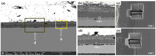
Figure 2.
Cross section of the oxide film observed under a SEM using a focused ion beam. (a) shows the topography in BSE mode; (b,d) correspond to the magnified images in (a), while (c,e) indicate the specific locations of the FIB cutouts, observed in SE2 mode.
Figure 3 presents the BF model morphology, SAED pattern images, and EDS mappings of FIB1 under TEM observation. As shown in Figure 3a, even the FIB1 sample extracted from the non-porous area contains a small number of pores, which is also reflected in the morphology depicted in Figure 2c. SAED analysis was conducted at various locations on the sample, as illustrated in Figure 3b–d. Combining these results with the element mappings in Figure 3e, we can identify Fe with a bcc structure at location b (PDF#50-1275), Cr2O3 with Mn at location c (PDF#38-1479), and FeCr2O4 at location d (PDF#24-0511). Notably, Cr2O3 forms a coherent layer approximately 0.3 μm thick along the junction of the IOZ and the matrix, with negligible O element present beneath this layer, while there is a partial enrichment of O and Cr on it. Given that the signals for Pb and Bi are weak and the rightmost position corresponds to noise during energy spectrum acquisition, this indicates that there is essentially no Pb infiltration in the non-porous IOZ region.
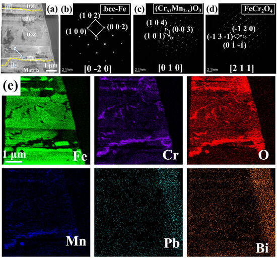
Figure 3.
FIB1 images observed under TEM: (a) morphology in BF mode; (b–d) correspond to SAED pattern images from different positions marked in (a); (e) displays the EDS mappings of Fe, Cr, O, Mn, Pb, and Bi.
Figure 4 presents the BF model morphology and EDS mappings of FIB2 under TEM observation. Figure 2b illustrates that the porous regions contain minimal Fe elements, yet are abundant in Cr, Mn, and O elements, along with some Pb infiltration. Additionally, a region rich in Cr, Mn, and O is observed at the junction of the matrix and the IOZ, which aligns with the findings presented in Figure 3e. The further amplification of various regions depicted in panel a is shown in Figure 4c–h, utilizing BF and DF image comparisons to assess the presence of precipitated phases. Numerous acicular precipitates are identified within both the matrix and porous regions, along with many fine grains in the porous area. A more detailed examination of the O/M junction, as illustrated in Figure 5, corresponds to the yellow box area in Figure 4a, revealing the presence of numerous pores and fine grains at the junction. Additionally, SAED analysis was conducted on region b, with the results presented in Figure 5b. The calibration results, combined with the energy spectrum data in Figure 5c, indicate that the phase present is Cr2O3 and bcc-Fe. It is evident that the Fe content in the porous region is low, primarily enriched with Cr, Mn, and O, along with evidence of Pb and Bi infiltration.
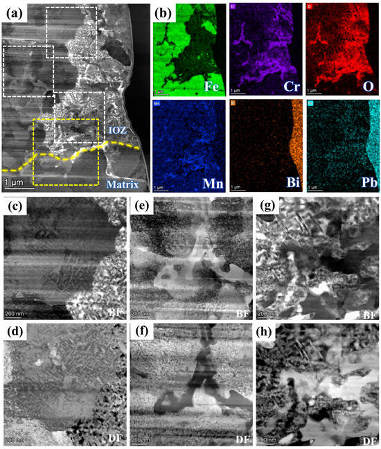
Figure 4.
FIB2 images observed under TEM: (a) morphology in HAADF mode; (b) shows the EDS mappings of Fe, Cr, O, Mn, Pb, and Bi; (c,e,g) and (d,f,h) are bright and dark field images corresponding to different positions in (a), respectively. The white dotted box area from top to bottom corresponds to (c,d), (e,f), (g,h) respectively. The yellow dotted box corresponds to Figure 5.
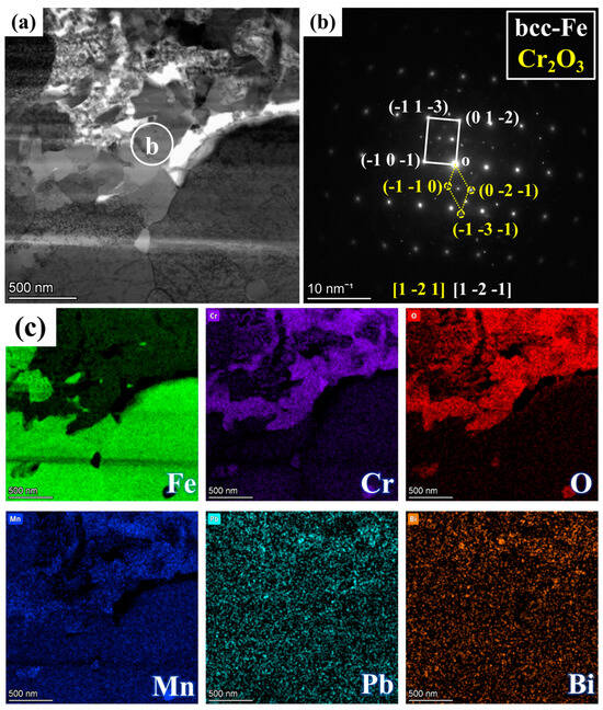
Figure 5.
Magnified image of the yellow box area in Figure 4a: (a) BF image, (b) SAED pattern corresponding to region b in (a), and (c) mappings of Fe, Cr, O, Mn, Pb, and Bi.
Figure 6 further illustrates the morphology, SAED analysis, and EDS mapping analysis of different elements in the region of Figure 4e under magnified HAADF mode. At the boundary between the porous and non-porous regions, a zone rich in light elements is observed, with the grains identified as Cr2O3 through SAED analysis, corroborated by the energy spectrum results in Figure 6c. Notably, in these acicular oxides, the Cr depletion zone alternates with the Fe depletion zone. Generally, areas rich in Cr oxides exhibit very low Fe content, while regions containing Fe show significantly reduced Cr levels. Mn is present between these two regions. To further investigate this phenomenon, the non-porous and porous regions of the IOZ are analyzed in Figure 7. The results in Figure 7a,b clearly indicate substantial Pb infiltration near these voids. Given the absence of hole positions in this area, it can be concluded that this is not due to noise interference. Moreover, the presence of Pb is consistent with the line scan results in Figure 1d. Figure 7d further magnifies the porous IOZ region, revealing that Pb infiltration primarily occurs near the voids. Additional HRTEM analysis of the needle-like region shows that Fe and Cr2O3 appear alternately throughout all non-porous IOZ regions, with numerous voids present. In porous regions, Fe and Cr2O3 also exhibit an alternating pattern. Specifically, Figure 7g,i demonstrates a clear orientation relationship between the areas of Cr2O3 and Fe ([1-21] Fe//[1-2-1]Cr2O3), indicating a close correlation between the oxidation of Cr and the matrix.
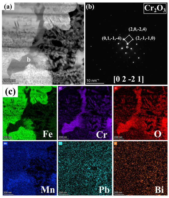
Figure 6.
Magnified image of Figure 4e: (a) BF image, (b) SAED pattern corresponding to region b in (a), and (c) mappings of Fe, Cr, O, Mn, Pb, and Bi.
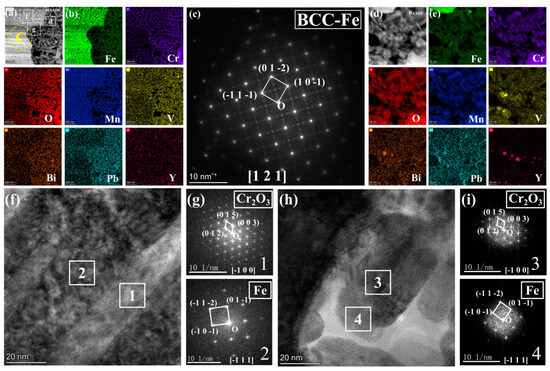
Figure 7.
(a) corresponds to the magnified HAADF image shown in Figure 4c; (b) EDS mappings of Fe, O, Mn, Cr, and Pb for (a); (c) presents the SAED pattern image for region b of a; (d) illustrates the enlarged HAADF image of region d of a; (e) EDS mappings of Fe, O, Mn, Cr, and Pb for (d); (f) includes the HRTEM image corresponding to region f in a; (g) provides the FFT pattern images for regions 1 and 2 in f; (h) displays the HRTEM image corresponding to region g in a; (i) presents the FFT pattern images for regions 3 and 4 in h.
4. Discussion
4.1. Oxidation Mechanism of the OOL and IOL
After 1000 h of exposure to low-carbon 9Cr-ODS steel in LBE saturated with oxygen at 500 °C, three layers of oxide film were formed: the outer layer, the inner layer, and the IOZ layer (see Figure 1, Figure 3 and Figure 4). The inner layer is a relatively dense FeCr2O4, while the outer layer is Fe3O4 that has been infiltrated by LBE. The characteristics of the IOZ layer are discussed in Section 4.2. In our previous experiments, corrosion tests were conducted on steel samples for durations of 1 h, 100 h, and 200 h under identical conditions [35]. The results indicated that the IOL consisted of FeCr2O4, while the outer layer was identified as Fe3O4. Therefore, considering that the EDS results presented in Figure 1c are consistent with previous findings, it is reasonable to conclude that the outer layer is indeed Fe3O4.
The mechanism underlying the formation of a double-layer oxide film during lead–bismuth corrosion can be elucidated using a widely accepted usable space model [26,27,28]. This model posits that the diffusion of Fe is critical to the growth of the oxide film. Figure 8 illustrates the thermodynamic Ellingham diagram, which indicates that for different oxides, the lower the Gibbs free energy, and the more readily they tend to form preferentially [36]. As Fe diffuses outward, it reacts with O in LBE, leading to the deposition of an Fe3O4 layer. Concurrently, as Fe moves outward and creates vacant sites, O infiltrates the matrix and reacts with Cr to form Cr2O3. As illustrated in Figure 8, when the O content is adequate, Fe will further react with Cr2O3 to produce FeCr2O4. The oxygen concentration in molten LBE can be calculated using the following formula [6,36]:
where C represents the mass percentage concentration of dissolved oxygen, A and B are constants, and T denotes the temperature in Kelvin. According to the literature, at approximately 500 °C, the concentration of dissolved oxygen in LBE ranges from 10−2 to 10−3 wt.%. This level of oxygen is sufficient for Cr2O3 to react with Fe, resulting in the formation of FeCr2O4. Therefore, the substrate surface will gradually develop a double-layer oxide film. The relatively dense nature of FeCr2O4 in the inner layer, which provides effective protection, can be attributed to two factors. First, FeCr2O4 becomes denser upon expansion due to its high Pb ratio [37,38,39]. Second, in the spinel structure, Cr3+ occupies the tetrahedral sites, while Fe2+ occupies the octahedral sites. Consequently, Fe has limited diffusion through the tetrahedral gaps but can diffuse through the octahedral gaps [26,27,28]. This mechanism effectively reduces the diffusion rate of Fe, thereby slowing down the corrosion rate. In contrast, the outer layer is directly exposed to LBE, leading to the dissolution of Fe into LBE and the formation of a porous Fe3O4 structure. This allows LBE to penetrate the vacancies created by the loss of Fe, resulting in the observed phenomenon of LBE ingress into the outer layer, as illustrated in Figure 1c. Moreover, it is evident that the infiltration of Pb is significantly more pronounced than that of Bi, as demonstrated by numerous studies. One possible explanation is that Pb absorption is stronger than that of Bi, making it easier to penetrate [36].
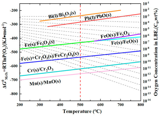
Figure 8.
Ellingham diagrams of the standard Gibbs free energy of the concentration of dissolved oxygen in liquid LBE [37].
4.2. Oxidation Mechanism of IOZ
The IOZ primarily consists of Cr2O3 and an unoxidized Fe matrix. In many regions, the oxidized Cr exhibits a needle-like morphology, while relatively coherent Cr2O3 is present in the OM (see Figure 3, Figure 4 and Figure 5). The following discussion explores the relationship between the IOZ and corrosion time as well as the factors contributing to the formation of porous and non-porous IOZs.
We conducted corrosion tests on this steel for 1 h, 100 h, and 200 h, and no significant IOZ formation was observed. However, when the corrosion time was extended to 1000 h in this experiment, IOZ formation was detected. This occurs because, with prolonged corrosion time, the oxide film thickness increases, enhancing the protective layer, which slows down oxygen infiltration and leads to the preferential oxidation of Cr. In summary, the protection provided by the IOL is the primary reason for the formation of the IOZ. Cr2O3 exhibits the lowest Gibbs free energy, indicating that Cr has the highest oxidation priority [36]. When the oxygen content is sufficient, Cr2O3 can continue to react with Fe to form FeCr2O4. However, as the IOL becomes progressively thicker, the oxygen concentration at the interface between the matrix and the IOL decreases. Consequently, Cr can only be preferentially oxidized under these conditions. Due to the grain boundary serving as a fast diffusion channel, oxygen preferentially penetrates along the grain boundaries and oxidizes them, which accounts for the tree-like morphology observed in the IOZ. As O approaches the depleted position, Cr and Mn are preferentially oxidized, resulting in the formation of a coherent layer of Cr2O3 interspersed with Mn (see Figure 3, Figure 4 and Figure 5). Chen et al. [40] investigated the corrosion of T91 steel in supercritical water for 1500 h and identified four distinct oxidation types. The outer layer was composed of Fe3O4, while the inner layer consisted of FeCr2O4. The primary component of the IOZ was preferentially oxidized chromium, and coherent Cr2O3 was also detected at the outer margin. The authors propose that when the Cr/O ratio reaches a certain critical threshold, Cr2O3 is generated concurrently with the depletion at the edge, which aligns with the observations from our experiment.
There are two primary morphologies of the IOZ: non-porous and porous. As shown in Figure 2c,e, the SE2 mode of TEM reveals that the observed IOZ already exhibits distinct porous regions. Therefore, these voids are not a result of FIB excisions but are pre-existing. Both the porous and non-porous IOZs contain acicular Cr2O3 (see Figure 7). The most significant difference is that the porous IOZ is markedly Fe-deficient (Figure 3 and Figure 4). For these needle-like Cr2O3 structures, the uneven distribution of Cr within the matrix can be ruled out based on previous characterizations [17]. Therefore, the formation of acicular oxides is likely due to the selective oxidation of O after it infiltrates the matrix. With the increase of O infiltration and Cr diffusion in the short range, the Cr-rich oxide will grow and appear with a needle-like morphology, and create a Cr-poor zone around it. Ye et al. [41] investigated the corrosion of T91 steel in oxygen-saturated liquid LBE at 550 °C for 2000 h. They observed that the chromium oxides in the IOZ exhibited a needle-like distribution, with chromium-poor regions forming around them. Similarly, Zhang et al. [42] found that after SIMP steel was corroded in oxygen-saturated LBE at 600 °C for 2000 h, needle-like Cr2O3 and FeCr2O4 phases emerged in the IOZ, demonstrating a significant orientation relationship with the matrix. The formation of this acicular Cr2O3 is attributed to the short-range diffusion of Cr in the matrix and its oxidation growth at grain boundaries or within the crystal. As mentioned earlier, O infiltration preferentially oxidizes along grain boundaries. However, the primary grain boundaries are mainly VN. Although previous characterizations showed a few precipitates coupled with VN and Cr, most grain boundaries do not contain Cr. This implies that, in addition to the diffusion of Cr to the grain boundaries, O will gradually infiltrate the grain interior, leading to internal oxidation and the formation of Cr-depleted regions. These regions create a concentration gradient, facilitating the diffusion of surrounding Cr to these depleted areas. The nucleation and growth of Cr2O3 then result in the needle-like structure observed. Figure 7g,i illustrates a clear orientation relationship between Cr2O3 and Fe areas, indicating that Cr oxides initially form in the matrix and subsequently grow into a needle-like morphology (Figure 6 and Figure 7).
The diffusion of Fe primarily depends on the concentration gradient of Fe and the concentration of O [43,44,45]. The presence of O promotes the outward diffusion and oxidation of Fe. The Fe-deficient phenomenon in the porous IOZ suggests significant Fe diffusion. In some areas, a minor amount of LBE might have infiltrated the IOL, likely due to prolonged corrosion time. In Figure 1d, Pb peaks are observed in both the IOL and IOZ regions, and point scan results corroborate Pb infiltration in these areas. The slow infiltration of Pb can serve as a nanochannel for Fe and O diffusion, thereby increasing the Fe diffusion rate. Figure 4, Figure 5, Figure 6 and Figure 7 show a low Fe content in the porous regions, supporting our hypothesis. Additionally, O can enter the IOZ via infiltrated Pb and extensively oxidize the residual Cr, explaining the high Cr oxidation near the porous IOZ (see Figure 4). Some studies have proposed that an IOZ will gradually transform into an IOL as the corrosion process progresses [4,34]. Therefore, over time, the porous IOZ may affect the densification of a subsequently grown IOL, negatively impacting the material’s long-term corrosion resistance.
5. Conclusions
In this study, we corroded low-carbon 9Cr-ODS steel in oxygen-saturated liquid LBE at 500 °C for 1000 h. SEM and TEM were employed to characterize the cross section of the oxide film that formed after corrosion in detail. The conclusions are as follows:
- After 1000 h of corrosion at 500 °C, three distinct layers of oxide film were formed on the substrate’s surface: an Fe3O4 layer infiltrating the LBE, a dense FeCr2O4 layer, and an IOZ layer arranged from outside to inside.
- The formation of the Fe3O4 and FeCr2O4 layers is attributed to the diffusion of Fe. The outward diffusion of Fe leads to the growth of the Fe3O4 layer, while the inward diffusion of O results in the formation of the FeCr2O4 layer.
- The IOZ primarily consists of unoxidized matrix and Cr2O3, exhibiting two morphologies: one porous, and the other non-porous.
- The predominant oxide in the IOZ is Cr2O3. This is attributed to the dense oxide film, which reduces the O content near the substrate and preferentially facilitates the formation of Gibbs free energy associated with low Cr2O3.
Author Contributions
C.Y.: Conceptualization, Methodology, Software, Investigation, Formal Analysis, and Writing—Original Draft; T.L.: Data Curation and Writing—Original Draft; Y.Y.: Visualization and Investigation; Y.W.: Resources and Supervision; Y.X.: Software and Validation; D.Y.: Visualization and Writing—Review and Editing; P.L.: Software, Validation, Supervision, and Writing—Review and Editing. J.Q.: Conceptualization, Funding Acquisition, and Resources. All authors have read and agreed to the published version of the manuscript.
Funding
This work was financially supported by the Research Project of Shanxi Province (Grant No. 2023SYJ18), and the National Natural Science Foundation of China (Grant No. 12475267).
Data Availability Statement
The raw data required to reproduce these findings cannot be shared at this time as the data also forms part of an ongoing study.
Acknowledgments
We thank Jinyu Zheng of China University of Geosciences (Wuhan) for his help in TEM analysis.
Conflicts of Interest
The authors declare no conflict of interest.
References
- Buckthorpe, D. Introduction to Generation IV nuclear reactors. In Structural Materials for Generation IV Nuclear Reactors; Woodhead Publishing: Sawston, UK, 2017; pp. 1–22. [Google Scholar]
- Aitkaliyeva, A.; He, L.; Wen, H.; Miller, B.; Bai, X.M.; Allen, T. 7—Irradiation effects in Generation IV nuclear reactor materials. In Structural Materials for Generation IV Nuclear Reactors; Yvon, P., Ed.; Woodhead Publishing: Sawston, UK, 2017; pp. 253–283. [Google Scholar]
- Abram, T.; Ion, S. Generation-IV nuclear power: A review of the state of the science. Energy Policy 2008, 36, 4323–4330. [Google Scholar] [CrossRef]
- Zhang, J. A review of steel corrosion by liquid lead and lead–bismuth. Corros. Sci. 2009, 51, 1207–1227. [Google Scholar] [CrossRef]
- Ballinger, R.G.; Lim, J. An overview of corrosion issues for the design and operation of high-temperature lead- and lead-bismuth-cooled reactor systems. Nucl. Technol. 2004, 147, 418–435. [Google Scholar] [CrossRef]
- Zhang, J.; Li, N. Review of the studies on fundamental issues in LBE corrosion. J. Nucl. Mater. 2008, 373, 351–377. [Google Scholar] [CrossRef]
- Lu, C.; Lu, Z.; Wang, X.; Xie, R.; Li, Z.; Higgins, M.; Liu, C.; Gao, F.; Wang, L. Enhanced Radiation-tolerant Oxide Dispersion Strengthened Steel and its Microstructure Evolution under Helium-implantation and Heavy-ion Irradiation. Sci. Rep. 2017, 7, 40343. [Google Scholar] [CrossRef]
- Ukai, S.; Ohtsuka, S.; Kaito, T.; de Carlan, Y.; Ribis, J.; Malaplate, J. 10—Oxide dispersion-strengthened/ferrite-martensite steels as core materials for Generation IV nuclear reactors. In Structural Materials for Generation IV Nuclear Reactors; Yvon, P., Ed.; Woodhead Publishing: Sawston, UK, 2017; pp. 357–414. [Google Scholar]
- Xu, H.; Lu, Z.; Wang, D.; Liu, C. Microstructure Refinement and Strengthening Mechanisms of a 9Cr Oxide Dispersion Strengthened Steel by Zirconium Addition. Nucl. Eng. Technol. 2017, 49, 178–188. [Google Scholar] [CrossRef]
- Fazio, C.; Balbaud, F. 2—Corrosion phenomena induced by liquid metals in Generation IV reactors. In Structural Materials for Generation IV Nuclear Reactors; Yvon, P., Ed.; Woodhead Publishing: Sawston, UK, 2017; pp. 23–74. [Google Scholar]
- Zhang, J.; Li, Y.; Wang, G.; Bao, F.; Rui, X.; Shi, Q.; Yan, W.; Shan, Y.; Yang, K. Effects of Heat Treatment on Microstructure and Mechanical Properties of a Bimodal Grain Ultra-Low Carbon 9Cr-ODS Steel. Acta Metall. Sin. 2022, 58, 623–636. [Google Scholar]
- Zhang, J.; Li, Y.; Rui, X.; Yan, W.; Silver, A.; Yang, K. Study on microstructure and mechanical properties of 9Cr-ODS steel prepared by powder hot forging. J. Iron Steel Res. 2021, 33, 8. [Google Scholar]
- Grybėnas, A.; Makarevičius, V.; Baltušnikas, A.; Lukošiūtė, I.; Kriūkienė, R. Correlation between structural changes of M23C6 carbide and mechanical behaviour of P91 steel after thermal aging. Mater. Sci. Eng. A 2017, 696, 453–460. [Google Scholar] [CrossRef]
- Aghajani, A.; Somsen, C.; Eggeler, G. On the effect of long-term creep on the microstructure of a 12% chromium tempered martensite ferritic steel. Acta Mater. 2009, 57, 5093–5106. [Google Scholar] [CrossRef]
- Abe, F. Precipitate design for creep strengthening of 9% Cr tempered martensitic steel for ultra-supercritical power plants. Technol. Adv. Mater. 2008, 9, 013002. [Google Scholar] [CrossRef]
- Kimura, K.; Toda, Y.; Kushima, H.; Sawada, K. Creep strength of high chromium steel with ferrite matrix. Int. J. Press. Vessels Pip. 2010, 87, 282–288. [Google Scholar] [CrossRef]
- Xu, Y.; Yun, D.; Yan, X.; Zhang, P.; Yan, W.; Li, Y.; Li, C.; Li, J.; Zhang, T.; Li, J.; et al. Effects of Fe self-ion irradiation on a low carbon MX-ODS steel at 550 °C. Front. Energy Res. 2023, 10, 988745. [Google Scholar] [CrossRef]
- Tsisar, V.; Schroer, C.; Wedemeyer, O.; Skrypnik, A.; Konys, J. Long-term corrosion of austenitic steels in flowing LBE at 400 °C and 10−7 mass% dissolved oxygen in comparison with 450 and 550 °C. J. Nucl. Mater. 2016, 468, 305–312. [Google Scholar] [CrossRef]
- Müller, G.; Heinzel, A.; Konys, J.; Schumacher, G.; Weisenburger, A.; Zimmermann, F.; Engelko, V.; Rusanov, A.; Markov, V. Results of steel corrosion tests in flowing liquid Pb/Bi at 420–600 °C after 2000 h. J. Nucl. Mater. 2002, 301, 40–46. [Google Scholar] [CrossRef]
- Müller, G.; Heinzel, A.; Konys, J.; Schumacher, G.; Weisenburger, A.; Zimmermann, F.; Engelko, V.; Rusanov, A.; Markov, V. Behavior of steels in flowing liquid PbBi eutectic alloy at 420–600 °C after 4000–7200 h. J. Nucl. Mater. 2004, 335, 163–168. [Google Scholar] [CrossRef]
- Schroer, C.; Wedemeyer, O.; Novotny, J.; Skrypnik, A.; Konys, J. Selective leaching of nickel and chromium from Type 316 austenitic steel in oxygen-containing lead–bismuth eutectic (LBE). Corros. Sci. 2014, 84, 113–124. [Google Scholar] [CrossRef]
- Tian, S.J. Growth and Exfoliation Behavior of the Oxide Scale on 316L and T91 in Flowing Liquid Lead-Bismuth Eutectic at 480 °C. Oxid. Met. 2020, 93, 183–194. [Google Scholar] [CrossRef]
- Tsisar, V.; Schroer, C.; Wedemeyer, O.; Skrypnik, A.; Konys, J. Corrosion behavior of austenitic steels 1.4970, 316L and 1.4571 in flowing LBE at 450 and 550 °C with 10−7 mass% dissolved oxygen. J. Nucl. Mater. 2014, 454, 332–342. [Google Scholar] [CrossRef]
- Du, Q.; Chen, J.; Yun, D.; Gu, L.; Long, B.; Lu, C.; Li, Y.; Guo, S. Effect of post-annealing on the oxidation behavior of hot rolled ODS-FeCrAl steel in liquid lead. Corros. Sci. 2024, 228, 111815. [Google Scholar] [CrossRef]
- Zhu, Z.; Tan, J.; Zhang, Z.; Wu, X.; Li, J.; Wang, X.; Han, E.-H.; Ke, W. Corrosion behaviors of ODS-FeCrAl in oxygen-saturated lead-bismuth eutectic at 550 °C: Effects of grain boundaries and minor elements. J. Nucl. Mater. 2023, 587, 154710. [Google Scholar] [CrossRef]
- Martinelli, L.; Balbaud-Célérier, F.; Picard, G.; Santarini, G. Oxidation mechanism of a Fe-9Cr-1Mo steel by liquid Pb–Bi eutectic alloy (Part III). Corros. Sci. 2008, 50, 2549–2559. [Google Scholar] [CrossRef]
- Martinelli, L.; Balbaud-Célérier, F.; Terlain, A.; Bosonnet, S.; Picard, G.; Santarini, G. Oxidation mechanism of an Fe-9Cr-1Mo steel by liquid Pb–Bi eutectic alloy at 470 °C (Part II). Corros. Sci. 2008, 50, 2537–2548. [Google Scholar] [CrossRef]
- Martinelli, L.; Balbaud-Célérier, F.; Terlain, A.; Delpech, S.; Santarini, G.; Favergeon, J.; Moulin, G.; Tabarant, M.; Picard, G. Oxidation mechanism of a Fe–9Cr–1Mo steel by liquid Pb–Bi eutectic alloy (Part I). Corros. Sci. 2008, 50, 2523–2536. [Google Scholar] [CrossRef]
- Shi, Q.; Yan, W.; Li, Y.; Zhang, N.; Shan, Y.; Yang, K.; Abe, H. Oxidation behavior of ferritic/martensitic steels in flowing supercritical water. J. Mater. Sci. Technol. 2021, 64, 114–125. [Google Scholar] [CrossRef]
- Schroer, C.; Konys, J. Quantification of the Long-Term Performance of Steels T91 and 316L in Oxygen-Containing Flowing Lead-Bismuth Eutectic at 550 °C. J. Eng. Gas Turbines Power 2010, 132, 082901. [Google Scholar] [CrossRef]
- Xiao, J.; Gong, X.; Xiang, C.; Yu, Z.; Wang, H.; Zhao, K.; Liu, C.; Zhuo, H.; Qiu, S.; Yin, Y. A refined oxidation mechanism proposed for ferritic-martensitic steels exposed to oxygen-saturated liquid lead-bismuth eutectic at 400 °C for 500 h. J. Nucl. Mater. 2021, 549, 152852. [Google Scholar] [CrossRef]
- Zhao, Y.; Ding, S.; Du, Y.; Yang, K.; Liu, S. Effect of long-term thermal aging on lead-bismuth eutectic corrosion behavior of 9Cr ferritic/martensitic steel. J. Mater. Sci. Technol. 2025, 210, 299–311. [Google Scholar] [CrossRef]
- Yeliseyeva, O.; Tsisar, V.; Benamati, G. Influence of temperature on the interaction mode of T91 and AISI 316L steels with Pb–Bi melt saturated by oxygen. Corros. Sci. 2008, 50, 1672–1683. [Google Scholar] [CrossRef]
- Gong, X.; Short, M.P.; Auger, T.; Charalampopoulou, E.; Lambrinou, K. Environmental degradation of structural materials in liquid lead- and lead-bismuth eutectic-cooled reactors. Prog. Mater. Sci. 2022, 126, 100920. [Google Scholar] [CrossRef]
- Yang, C.; Xu, Y.; Yun, D.; Zhao, B.; Liu, W.; Gao, R.; Xie, S.; Qiu, J. Early corrosion behavior of low carbon 9Cr-ODS steel in high temperature oxygen-saturated lead-bismuth eutectic. Corros. Sci. 2024, 236, 112285. [Google Scholar] [CrossRef]
- Schroer, C.; Konys, J. Physical Chemistry of Corrosion and Oxygen Control in Liquid Lead and Lead-Bismuth Eutectic; Forschungszentrum Karlsruhe: Karlsruhe, Germany, 2007. [Google Scholar]
- Yamamoto, J.; Yoshino, T.; Yamazaki, D.; Higo, Y.; Tange, Y.; Torimoto, J. Thermal expansion of natural mantle spinel using in situ synchrotron X-ray powder diffraction. J. Mater. Sci. 2019, 54, 139–148. [Google Scholar] [CrossRef]
- Pilling, N.; Bedworth, R. The oxidation of metals at high temperatures. J. Inst. Met. 1923, 29, 529–582. [Google Scholar]
- Kubaschewski, O.; Hopkins, B.E. Oxidation of Metals and Alloys; Butterworths: Washington, DC, USA, 1962. [Google Scholar]
- Chen, K.; Zhang, L.; Shen, Z. Understanding the surface oxide evolution of T91 ferritic-martensitic steel in supercritical water through advanced characterization. Acta Mater. 2020, 194, 156–167. [Google Scholar] [CrossRef]
- Ye, Z.; Wang, P.; Dong, H.; Li, D.; Zhang, Y.; Li, Y. Oxidation mechanism of T91 steel in liquid lead-bismuth eutectic: With consideration of internal oxidation. Sci. Rep. 2016, 6, 35268. [Google Scholar] [CrossRef]
- Zhang, L.; Yan, W.; Shi, X.; Li, Y.; Shi, Q.; Shan, Y.; Yang, K.; Zheng, S. On oxidation film structure of SIMP steel exposed in stagnant oxygen-saturated LBE at 600 °C. Corros. Sci. 2024, 230, 111927. [Google Scholar] [CrossRef]
- Aerts, A.; Gavrilov, S.; Manfredi, G.; Marino, A.; Rosseel, K.; Lim, J. Oxygen-iron interaction in liquid lead-bismuth eutectic alloy. Phys. Chem. Chem. Phys. 2016, 18, 19526–19530. [Google Scholar] [CrossRef]
- Kolotinskii, D.; Nikolaev, V. Formation and Dissolution of Porous Magnetite Layer in Contact with Lead-Bismuth Eutectic: Locally Equilibrium Thermodynamic Model. Corros. Sci. 2023, preprint. [Google Scholar] [CrossRef]
- Müller, G.; Heinzel, A.; Schumacher, G.; Weisenburger, A. Control of oxygen concentration in liquid lead and lead–bismuth. J. Nucl. Mater. 2003, 321, 256–262. [Google Scholar] [CrossRef]
Disclaimer/Publisher’s Note: The statements, opinions and data contained in all publications are solely those of the individual author(s) and contributor(s) and not of MDPI and/or the editor(s). MDPI and/or the editor(s) disclaim responsibility for any injury to people or property resulting from any ideas, methods, instructions or products referred to in the content. |
© 2025 by the authors. Licensee MDPI, Basel, Switzerland. This article is an open access article distributed under the terms and conditions of the Creative Commons Attribution (CC BY) license (https://creativecommons.org/licenses/by/4.0/).