1. Introduction
Anaerobic digestion (AD) is the bacterial conversion of an organic feedstock by microorganisms in the absence of oxygen into biogas and digestate. In order to achieve its potential as a renewable fuel the biomethane generated from AD must be purified to “fossil grid” specification with a purification of >98%, e.g., for EN-16723 grid-injection standards [
1]. The primary constituents of biogas from AD consists of methane 50–70 v%, CO
2 30–50%, and H
2S < 1%). The contaminants are very corrosive, especially H
2S, and also inhibit combustion; therefore, its maximum available energy value as a ‘renewable national-grid gas’ or ‘renewable transport gas’ can only be achieved by purifying methane to 98 v%. Biomethane purification has been achieved by various competing technologies, such as pressure-swing adsorption (PSA), cryogenic separation, chemical washing (water, amines, alkaline solutions) and membrane technology; unfortunately, these all have high capital and operating costs (CAPX & OPEX). These are optimal at greater than 500 m
3/h (STP) of biogas, escalating significantly at throughputs of less than 200 m
3/h.
The trend throughout Europe is for smaller (20–200 m3/h) biomethane-purification capacities. It will enable a very wide range of potential small anaerobic-digester users, such as dairy farmers with 50–80 cows, and late-cut silage and beet, to become self-sufficient in producing enough bio-methane to support processes (home/dairying operations) and transport (car/tractor, etc.), as well as AD operations at wastewater-treatment plants.
Small-scale AD has enormous potential globally to conveniently supply renewable energy locally (secure from global energy supply volatility). It is only in Scandinavia and New Zealand where sophisticated, but very capital- and labour-intensive, AD-aggregation models are used, and where they make significant contributions to national-energy inventories. Moreover, the initial goal of this project is to develop this technology in the small-scale market and demonstrate that the technology is scalable linearly; from this initial experience, it has the potential to work equally well for larger-throughput facilities, generating substantial CAPEX and OPEX savings in wastewater treatment.
NBs are gas bubbles that are defined by their diameter, which is typically in the nanometre range. This very small size gives NBs characteristics that are very different from larger micron-sized bubbles. NBs typically exhibit greater metastability when compared to their micron-sized counterparts, and they exhibit several unique physical and mechanical characteristics. These include an enhanced solubility of a gas in water, an extremely high surface area/volume ratio, reduced or virtually eliminated buoyancy, greater zeta potentials, and the generation of free radicals [
2,
3,
4], sometimes due to electrostatic effects from dipolar alignment [
5]. In contrast, micron-sized bubbles decrease in size and eventually disappear underwater because of the rapid dissolution of the interior gas. This patented, innovative nanobubble (NB) technology has potential to reduce at least several-fold the CAPEX and OPEX of AD [
1], and it is for small-scale operations where the NB technology offers a competitive and key advantage, despite using NB-enhanced water-washing operations for biogas upgrade as an inherently scalable technology. The bench-scale results for gas-in-liquid accommodation have shown that several-fold increases for gases, above achievable according to Henry’s Law solubility level, have been realised by using this new technology; the NBs in the liquid are highly metastable.
Surveying some advances of nanobubble applications in the important wastewater field, by using mechanisms like collisions, attachment, and detachment [
6] in the flotation process, NB-enhanced floatation operations in seawater desalination have demonstrated promise in more recent studies on NBs in water treatment and flotation. Optimising NB-mediated flotation phenomena in mineral recovery and flotation kinetics in general has been investigated in terms of the best way to generate and detect NBs (e.g., optimal surfactant deployment strategy), such as electrolysis, hydrodynamic cavitation, and ultrasonication) [
7]. Due to their increased mass-transfer rates and collision efficiency, among other benefits, micro-nanobubbles have also recently been more thoroughly studied and appreciated, making them particularly promising for water treatment applications like flotation and disinfection [
8]. These more recent studies of NBs and their potential to enhance flotation and water treatment processes provide more economical and efficient alternatives to the current state-of-the-art aeration bubbling methods [
6,
7,
8].
A key application area where nanobubble generation is expected to have a large impact is differential CO
2-stripping from biogas, or biogas ‘upgrade’—originating from anaerobic digestion (AD)—with the European biogas market set to reach USD 10–11 billion by 2026 (
vide infra) [
1,
9].
In terms of previous exploration for the role of nanobubble sin improving the efficiency and performance of AD unit operations, let us consider some foundational previous work. Considering methanogenesis and hydrolysis per se, it has been found that nanobubbles improve these rate-limiting AD processes: NBs boost substrate accessibility and enzyme activity because of their small size and large surface area per unit volume [
10]. In an AD context, nanobubbles can also serve to boost facultative bacteria, enhance the electron transport system, and lower the level of sulpides and volatile fatty acids [
10,
11]. Increased microbial activity in AD processes has also been found by NBs, with enhanced capacity of microorganisms to withstand stressors such as high salinity and harmful substances, which enhances their overall performance [
11,
12]. The generation of reactive species by certain nanobubbles has the ability to alter microbial communities and accelerate degradation pathways [
10]. Tests of NBs in two-stage AD systems revealed increases in yields of both hydrogen and methane, as well as improved acidity and hydrolysis [
11,
12].
However, to date, the NB research efforts in the AD sector, as summarised in refs. [
10,
11,
12], has been based on mechanically generated NBs—which have drawbacks compared to the novel, electric-field-based approach described in the present study. Some key features of the highly novel and exciting electric-field nanobubble-generation approach for biogas upgrade are as follows:
very energy-efficient;
able to retrofit and increase the capacity of the existing footprint-constrained plant;
readily amenable to scale-up and continuous-flow operation;
portable, with easy shipping of nanobubble-generation equipment (e.g., skid-mounted);
additive-free;
removal of H2S in our single-step—nanobubble-formation process is also a unique approach;
low methane slippage (~1.3 v%);
no obvious regulatory difficulties.
These features distinguish this approach [
13] quite dramatically from what is currently commercialised on the market, or even available in concept from fundamental knowledge of gas–liquid phenomena. In particular, the ability of the current NB-centric approach as applied to enhanced “water washing” as a CO
2- (and H
2S) removal technology is inherently more scalable than other CO
2-stripping (or “biogas-upgrade”) approaches, owing,
inter alia, to the lack of any need for a membrane or elevated pressures—meaning that gas compressor operations are not particularly needed for exit-stream pressure management emanating from the AD reactor itself. Added to these competitive NB-enhanced “water-washing” operations is the lower operating and capital costs of such membrane-free, lower-pressure operation—with the electric-field
modus operandi obviating the need for moving parts and much in the way of maintenance (owing to no biofouling of non-existent membranes, as is sadly not the case with corrosion-prone impeller blades failing in compressors due to H
2S attack, and fouled membranes of the status quo). The fact that essentially arbitrarily low or high capacity of biogas upgrade can be obtained means both upward and downward scalability in terms of biogas upgrade capacity—i.e., dramatically above and below the typical biomethane purification levels of 200–500 m
3/h typically used in current biogas-stripping operations.
The overall goal of this study is to consider NB-generation applications in the AD sector—not just enhanced water washing per se to absorb preferentially CO2, but also for the attendant and important up- and down-stream water/sludge-treatment processes.
2. Methodology
Prior to discussing the results of the electric-field approach for generating NBs, it is perhaps useful to consider other approaches for NB generation and compare them to the electric-field method.
In the “porous-membrane” approach to generating nanobubbles, fluid flow through porous media is the foundation of the first primary mechanical NB-generation technique [
14,
15,
16,
17]. In order to create bubbles, particularly in water, pressurised injection gas is introduced through the medium membrane. Metastable bubble sizes of less than 1 μm can be attained by shrinking the medium’s pore sizes. Various nanobubble-generator companies, for instance, all employ systems that involve injecting a pressurised gas into a passageway followed by a fine-carbon-based porous medium with pore diameters ranging from several nm to several tens of nm. The porous medium should adhere to a specified shortest-to-longest distance ratio between the medium and the flow passage, whether it is oriented horizontally or tilted downward. Other crucial elements in this system are the gas pressure and fluid flowrate. Some suggest passing the liquid–gas mixture through a filter or porous medium to reduce the size of the bubbles and only allow bubbles smaller than a threshold to pass through, although the majority of methods involve injecting the gas through a fine porous medium to create nanobubbles. Sang, for example, is providing a system that draws raw water through a Venturi section and uses water flow to generate a relative pressure that permits the drawing of gas [
18]. The gas–water mixture undergoes three filtering stages following pressurisation. Using a sponge, non-woven filter, or ceramic porous material, large bubble sizes and foreign particles are filtered in the first step. The second stage, which has beads stacked on top of one another, produces finer bubbles. The third stage, which has the same structural design as the first stage, filters the bubbles to create bubbles with almost the same size and nanoscale order.
In the “pressure-difference” category for generating NBs, a fluid may flow as a result of a mechanical crack between two points; the amount of turbidity in the flow depends on the crack’s size and other fluid characteristics. One of the basic principles utilised in certain techniques for the creation of nanobubbles is the mechanical pressure differential between two points in the flow of a liquid–gas mixture. In order to pressurise the gas–water mixture inside a tank, Toshihiko developed a pump that draws in gas and water [
19]. The pressurised mixture is connected to the site of nanobubble production via a pressure-regulating valve, which regulates the mixture’s pressure at the generating location. The discharge section of the system has an orifice that helps control the pressure at which nanobubbles are produced. For this system to generate nanobubbles of the proper size and population, the ratio of P2/P1, where P2 is the pressure before the orifice and P1 is the mixture pressure before the pressure-regulating valve, must be controlled. Static mixers can also be used sparingly to create pressure differences. The cavitation principle of nanobubble generation—featuring in a number of industrial-generator designs—also exploits the creation of pressure difference, and thence nanoscale bubbles [
17].
In the “shear-stress” method, a commonly used technique uses friction forces and shear stress to cause bubbles to gradually break into smaller ones until they are fine- and nano-sized. A few submersible NB-generator designs also use flow-rotational techniques, which are based on these frictional forces. Ho and others showed how a gas–water mixture passes through a chamber with a revolving shaft and various protruding units [
20,
21]. These units have the ability to rub the gas–water mixture and its surrounding surface, which could lead to smaller bubbles. The system is composed of several stages that first create microbubbles, which are subsequently reduced to create nanobubbles. Boundary-layer mixing is an optional feature that can be achieved by running a gas–water mixture through a lengthy hose. “Hammermill-rotation” and other submersible NB generators have a design with a “rotating-shaft” (and a porous membrane for bubble-size reduction towards the nanoscale range) [
22] both use the general idea of rotational-swirl flow arrangements based on the idea of shear-stress/friction-induced progressive bubble-size reduction.
Nanobubbles and/or nanodroplets can be created in gas–water systems by applying an external static electric field [
13] and exploiting dipole-orientation effects [
5]. It is possible to create nanobubbles or nanodroplets by electrostrictively capturing a subpopulation of nanobubbles (or -droplets) from the outer reaches of the upstream/incipient population of macro-, meso-, or microbubbles when this external electric field is present close to a volume of liquid containing a medium. This external-field-induced method works well for converting a significant percentage of upward-rising macro- and/or mesobubbles, as well as bubbles that flow vertically or horizontally, into ultra-dense, long-lived NBs. This low-maintenance, solar-powered, energy-efficient “sheathed-electrode” approach, which lacks moving parts, is ideal for off-grid operations [
13].
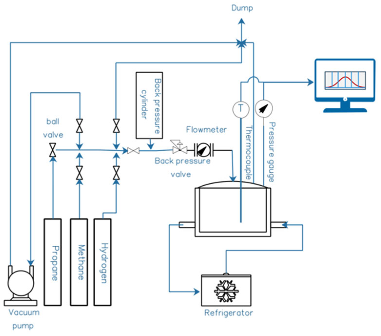
The novel method of NB formation was developed using an existing, state-of-the-art pressure-vessel rig—composed of a 0.3 L, 200 bar-rated stainless-steel pressure vessel linked up to a refrigerated temperature control system, with mechanical agitation on a rocking device. The details of the reactor are illustrated below in
Figure 1.
In short, one purifes biogas by generating NBs using this additive-free and energy-efficient patented technology [
7]. This is performed with the biogas in contact with liquid water (whether batch, continuous mode, fed batch, etc.). The reason for differential take-up of gas in nanobubble (NB) form into the water is that, even though de facto methane solubility is around 30 times higher than its Henry’s Law level in nanobubble form, this is still very small in terms of mass per volume in water (mg/L) in absolute terms. With conventional (standard molecular solvation) Henry’s Law solubility levels of CO
2 and H
2S’s being at least 40–50 times higher than CH
4 in terms of absolute mass-per-volume in water (i.e., in mg/L), the increase in CO
2 solubility due to NB creation though this breakthrough method results in much higher absolute f CO
2 and H
2S uptake into water. Quantitatively, mass-balance considerations show that CO
2 and H
2S levels transferred from the raw-biogas phase to the liquid (including in NB form) are approximately 16: and 25:1 compared to methane slippage into the water. So, we significantly purify methane, achieving ~95%-purity methane in a single-pass design). Microbes convert corrosive H
2S, precipitating sulphur, with iron addition, to useful FeSO
4.
At present, in proof-of-concept trials in a sub-litre pressure-vessel system (cf.
Figure 1), enrichment of 60:40%
v/
v methane–CO
2-biogas-mimicking gas mixture was up to ~96%
v/
v CH
4.
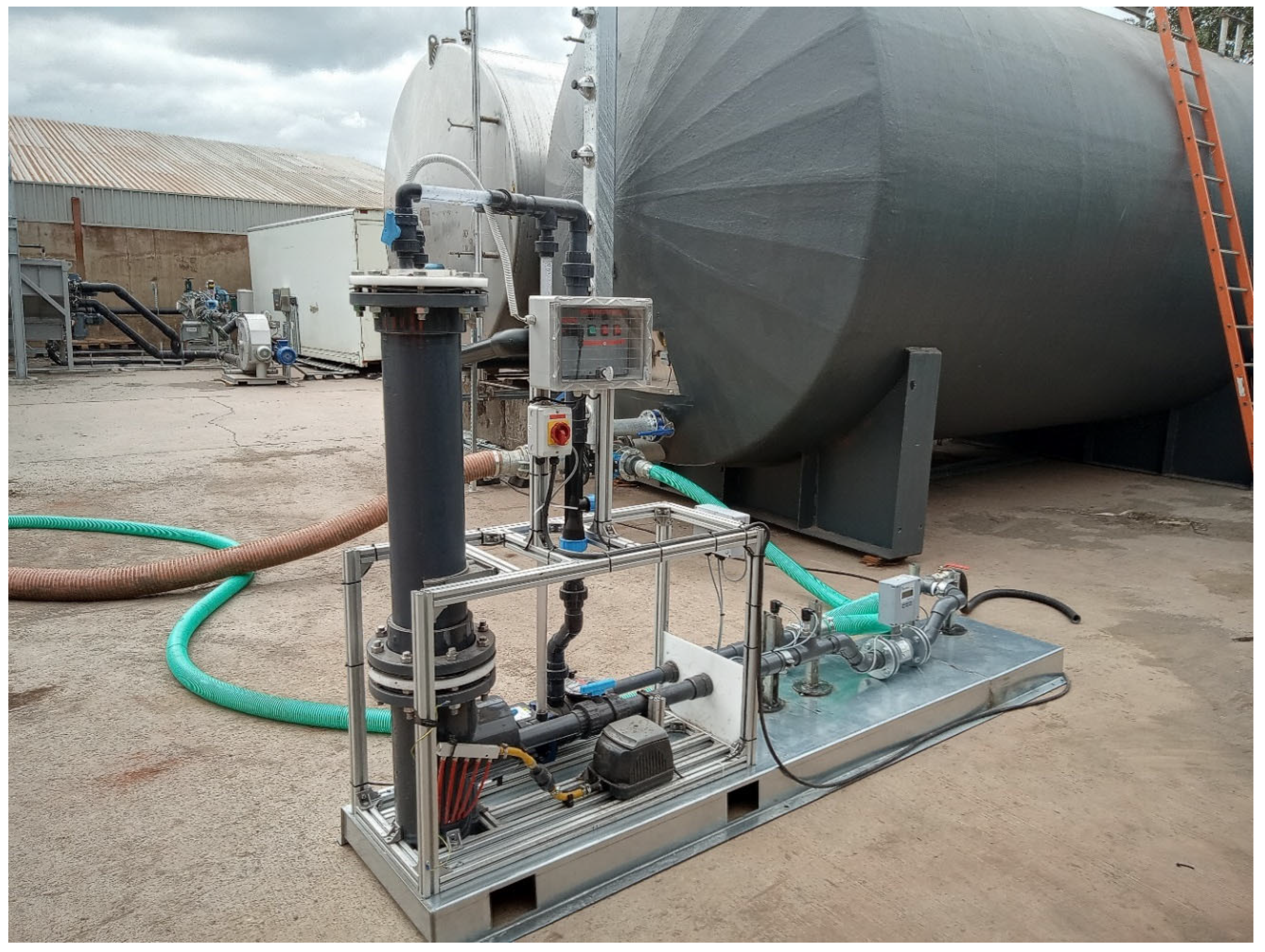
Following laboratory proof-of-concept validation, a circa 120–180 L/min water flow was put through a sidestream on a continuous-flow AquaB (Naas, Ireland) wastewater-processing nanobubble-generation unit at a biogas/AD plant—albeit using municipal water as the CO
2-capture agent. Gas flow was about 80 L/min at 6 bar g to a gas delivery manifold at the bottom of the electrostriction chamber using a compressor—in other words, a “driving force” of about 4 bar above the circa 2 bar g operating pressure of the unit. There is vortex-enhanced electrostriction, from upstream Venturi-screw microbubble generation from 40 L/min of atmospheric air drawn therethrough, and this converts the “mother” microbubbles into a sub-population of nanobubbles. This may be achieved by various gases. The already mentioned compressed gas supplied through a manifold connection at the bottom of the electrostriction column went upwards as a countercurrent gas supply line of generated microbubbles—followed by their conversion to nanobubbles on the internal electrode bank (cf.
Figure 2). The power draw of the electrostriction itself from mains AC is only about 8 W, and the bulk of that is AC-to-DC conversion overhead. Additional power is needed for pumping and air compressors, although this is very low indeed considering the impressive levels of aeration that may be achieved very rapidly (cf.
Section 3)—certainly a good deal less than a kiloWatt—so we may reasonably neglect much of the pumping costs in power-draw budgets. Although, to be fair, we perhaps allow a typical, industry guideline Venturi-draw power equivalence allowance of about 100–150 W. The compressor power was about 200 W up to ~1.5–2 bar g pressure inside the nanobubble generator.
The gases used were raw biogas, CO2, H2, and air for three different sets of runs. Multiple passes on (waste)water were performed with ~2 and 8 wt% non-dissolved solids in the case of air NBs for post-processing digestate wastewater aiming to oxygenate it with air NBs, e.g., for oxidation of H2S, nitrite, and ammonia, and other odorous and highly reactive forms of sulphur and nitrogen—thus affording this post-AD wastewater important treatment (thus removing more toxic elements from residual sludge to make it more useful as an organic fertiliser). Another goal was to impart either CO2 or H2 NBs into thick post-pyrolysis water/sludge mixture (with a solids content of the order of ~35–40%) to be fed into the AD system, with the goal of boosting the yield of methane and enriching the methane content of the biogas above the typical level of ~60% v/v. Finally, municipal water was passed a number of times through the NB generator in contact with raw biogas being supplied, with about 60% v/v methane content, in an effort to remove preferentially CO2 and H2S in the form of NBs, whilst minimising methane slippage.
The incoming raw biogas was roughly 61 ± 1.5% wt. methane, with about 0.08% wt. H
2S and the remainder as CO
2. The temperature range of operation was 17 to 23 deg C, with an upstream pressure of 6 bar g and at 80 L/min for the gas flow supply. In terms of the internals of the NB generator pictured in
Figure 1, the vertical section on the left housed the internal sheathed electrodes with 300 V DC applied, while a flow pattern was established across the bank of electrodes from vertically downward liquid flow pumped in from above this vertical section, from the right, as shown in
Figure 1. Inside the vertical electrostriction section, the densification of the liquid (which entrains macrobubbles, with such bubbles “fed” upstream by a Venturi section) took place, and this allowed the fragmentation of this original population of macrobubbles into smaller nanobubbles when in contact with the electric field of the electrodes. In short, the densification of the water around the larger upstream bubbles mediated by the static field leads to a partial vacuum around these bubbles, which serves to suck fluid “pockets” of gas into a population of “satellite” nanoscale bubbles surrounding the periphery of the original macro-/mesobubbles.
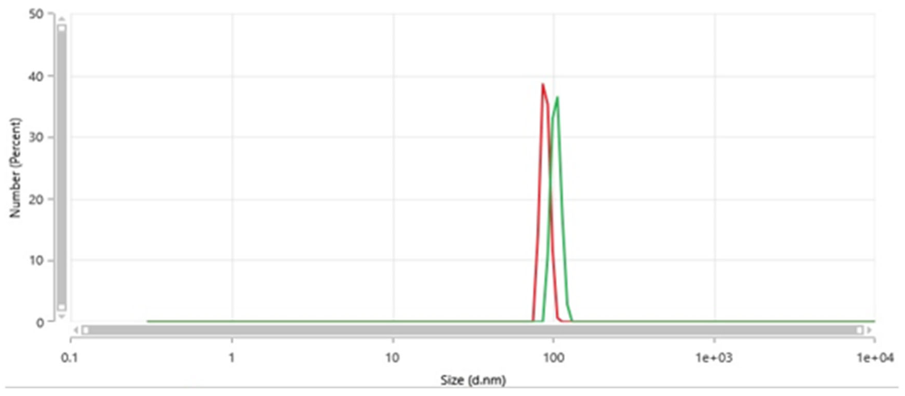
Figure 3 shows a couple of typical size distributions from Dynamic Light Scattering via a Malvern Zetasizer Pro (Malvern, UK) of filtered water passed through the nanobubble generator (such that the derived count rate is less than 100 k.c.p.s. [
13]); in any event, this water source shows no such nanoscale light-scattering features prior to passage therethrough (i.e., well below any instrument detection limits). In these examples, the typical diameter range is around 85–105 nm. The scale is up to 10 microns, and only these nanobubble features are present (with no detectable level of microbubbles); as such, light-scattering does not detect larger meso- and macrobubbles.
It should be noted that the industrial equipment produces NBs in this size range—although the electric-field approach, in general, tends to lead to NB sizes in this typical range, which are favourably lower compared to other methods [
13].
4. Conclusions
The present study has witnessed exciting applications of nanobubble gasification for various important applications in the anaerobic-digestion sector. The energy for biogas upgrade was about 0.48–0.95 kWhr per Nm
3 on a single-pass basis, with up to 95–96% purity and about 1.35% methane slippage—making this an ideal, lower-cost/lower-energy preliminary-treatment option—effectively, a superior water-washing technology. This can be deployed prior to more effective “latter-stage” treatment by membrane technologies for CO
2 (and H
2S) removal. The highly scalable version of this NB-empowered “water-washing” technology makes it highly economic at lower throughput levels and flowrates of AD-based biogas production [
9], although it can be deployed to substantially higher levels of biomethane production as well. Working hand in glove as an effective pre-treatment step ahead of less intensive downstream membrane treatment (if Grid-injection or food/beverage methane-purity levels are desired), this approach reduces both the capital and operating costs of membrane treatments, with a much lower downstream membrane treatment capacity needed—also prolonging the useful operating life of biogas upgrade membranes with less intensive maintenance schedules needed. Given that this differential—and, indeed, preferential—CO
2 and H
2S capture takes place essentially at ambient pressure, e.g., of the order of 0.5–1.5 bar g (as opposed to ~12–18 bar g in conventional amine scrubbing or membrane capture approaches to remove CO
2), then very little (to no) gas compressor capacity is needed—which reduces both operational and capital cost, and associated maintenance schedules, a very great deal; indeed, this is especially important, given that H
2S poisoning of compressor blades upstream of raw-biogas upgrade itself is an often-disabling and crippling problem in industrial biogas production, which is often ignored and afforded too little engineering operational attention in comparative technological analyses [
1]. However, if simple methane purity levels of the order of 94–95% are desired for gas engine and gas turbine usage, then the present NB-enabled water-washing technology may be contemplated directly, without the need for downstream membrane installation, and with little threat of H
2S poisoning to gas turbine/engine operation (e.g., minimisation of sulphide-related corrosion attack after the inlet-manifold section or in the combustion cylinders themselves).
The prospect of a simple course of nano-carbonation or –hydrogenation upstream of AD itself, in the post-pyrolysis sludge water stream, is also of much interest, and is operationally relatively simple. The finding of improved biomethane yield is encouraging, as the excellent surface-area-to-volume ratio afforded by the nanobubbles allows for a greater thermodynamic incentive towards biomethane production reactions in the AD chamber to push more towards the product: the boost in mass-transfer coefficient of the CO
2 and H
2 allows for Fick’s Law-driven diffusion of these from NB form into a higher regularly solvated liquid-phase concentration to “push” AD reactions more towards thermodynamic completion [
1,
9]. If anything, this may be an even more operationally facile and nearer-term scope for the deployment of NB technology for water treatment in the renewable-gas sector.
Turning to nano-aeration (or even oxygenation) of the downstream digestate sludge-water in that substantial water treatment challenge (with opportunities for prime organic-fertiliser production), there are substantial gains to be made from low-pressure aeration of this water stream, with the remarkable oxidative capacity of air nanobubbles on display at lower capital and operating expense. This is an advance similar in performance to Advanced Oxidation Processes at far lower operating cost, and with membrane-free and low-maintenance operation [
13].
Taken together, the findings of the present study indicate ample scope for electric-field nanobubbles technology to make substantial contributions to water treatment in the renewable-gas sector. However, although the present study acts as an important “proof-of-concept”, one also needs to consider the challenges of the wider industrialisation of this process. Although the operational cost in applying nanobubbles for “water washing” applied to biogas upgrade is very competitive (with beneficial H2S removal in the water also for lowering corrosive damage to compressor blades), as well as the low energy cost for downstream, post-AD digestate-water treatment, it must also considered that there are other operational and process barriers to be overcome in advance of widespread renewable-gas-industry uptake of this innovative technology. The main among them are the following: (i) the need for larger water flow in biogas upgrade per se, together with make-up and recycle-line engineering, (ii) feedforward ratio control loops for dissolved CO2 levels in the make-up and recycle water-flow lines, (iii) implementation of strict DC-voltage electrical safety standards with CE- and UL-certification (or equivalent), and (iv) IP- and ATEX ratings for efficient outdoor and all-weather usage, as well as (v) ISO Environmental Technology certification. In addition to these engineering and certification standards, including for operational control, the near-real-time measurement of water quality from downstream sludge treatment needs to be considered for incorporation into a feedback control loop for digestate-water flow, as well as potential voltage and DC duty-cycle variation using Model-Based Control strategies. Naturally, these control- and quality-engineering strategies are complex and involved and offer challenges to the scale-up of this technology, despite the prognosis for scalability being quite positive.


