Article

Effects of the ZrO2 Crystalline Phase and Morphology on the Thermocatalytic Decomposition of Dimethyl Methylphosphonate

1
Key Laboratory of Superlight Materials and Surface Technology, Ministry of Education, College of Material Sciences and Chemical Engineering, Harbin Engineering University, Harbin 150001, China
2
State Key Laboratory of NBC Protection for Civilian, Beijing 102205, China
*
Authors to whom correspondence should be addressed.
Nanomaterials 2024, 14(7), 611; https://doi.org/10.3390/nano14070611
Submission received: 8 February 2024 / Revised: 25 March 2024 / Accepted: 27 March 2024 / Published: 30 March 2024

Abstract

:
Thermocatalytic decomposition is an efficient purification technology that is potentially applicable to degrading chemical warfare agents and industrial toxic gases. In particular, ZrO2 has attracted attention as a catalyst for the thermocatalytic decomposition of dimethyl methylphosphonate (DMMP), which is a simulant of the nerve gas sarin. However, the influence of the crystal phase and morphology on the catalytic performance of ZrO2 requires further exploration. In this study, monoclinic- and tetragonal-phase ZrO2 (m- and t-ZrO2, respectively) with nanoparticle, flower-like shape and hollow microsphere morphologies were prepared via hydrothermal and solvothermal methods, and their thermocatalytic decomposition of DMMP was systematically investigated. For a given morphology, m-ZrO2 performed better than t-ZrO2. For a given crystalline phase, the morphology of hollow microspheres resulted in the longest protection time. The exhaust gases generated by the thermocatalytic decomposition of DMMP mainly comprised H2, CO2, H2O and CH3OH, and the by-products were phosphorus oxide species. Thus, the deactivation of ZrO2 was attributed to the deposition of these phosphorous oxide species on the catalyst surface. These results are expected to help guide the development of catalysts for the safe disposal of chemical warfare agents.

1. Introduction

Sarin (i.e., isopropyl methylphosphonofluoridate) is a nerve agent in vapour form with military applications [1] that enters the human body through respiration or via the skin and eyes to bind to acetylcholinesterase within the body. Just a small amount of short-term inhalation can damage the nervous system, and long-term excessive inhalation can have lethal effects [2]. The primary method for removing sarin is chromium-free impregnated carbon adsorption [3], but this technology only transfers sarin into the pores of the adsorption material, which can easily result in secondary pollution. Therefore, the adsorption material requires additional treatment to fully eliminate sarin. This had led to extensive efforts both domestically and internationally to develop innovative purification technologies against nerve agents. Owing to the extreme toxicity of sarin, dimethyl methylphosphonate (DMMP) has usually been used in experiments as a simulant because it is less toxic while having a similar structure.
Thermocatalytic decomposition involves using catalysts to reduce the activation energy and carrying out flameless combustion at lower ignition temperatures. The toxic molecules in the contaminated air adsorb onto the active sites of the catalysts, which results in a series of chemical decomposition effects that generate small molecular compounds such as CO2 and H2O. Thermocatalytic decomposition is widely applicable and efficient, and this purification technology is expected to replace conventional adsorption technologies [4,5,6,7,8,9,10]. Most studies on the thermocatalytic decomposition of DMMP have focused on using multivalent metal oxides [11,12,13,14]. Walenta et al. [14] investigated the DMMP decomposition performance of iron oxide and found that DMMP dissociates to form methoxy and methylphosphonic acid methyl ester (CH3O)P(O)2(CH3) at room temperature. At elevated temperatures, DMMP decomposes to form dimethyl ether, which reacts with lattice oxygen to generate reaction products such as H2 and CO2, and phosphorus oxide species accumulate as by-products on the catalyst surface. Gao et al. [12] prepared a loaded Cu–Ce catalyst using the equal-volume impregnation method. Their results indicated a strong interaction between Cu and Ce on CuO-5%CeO2/γ-Al2O3 and the promotion of surface-adsorbed oxygen, which improved the thermocatalytic decomposition of DMMP.
Zirconia (ZrO2) is a high-temperature-resistant metal oxide with acidic, alkaline, oxidative and reductive properties that has attracted tremendous attention in the fields of alkane conversion and catalytic cracking of gasoline [15,16,17]. Several studies have considered applying zirconium oxides as catalysts for the adsorption of DMMP [18,19]. Long et al. [19] synthesised zirconium oxide aerogels (ZrOxHy) using propylene oxide and aqueous ZrCl4 as raw materials and used in situ infrared spectroscopy to investigate their performance as an active adsorbent for DMMP. Their results indicated that DMMP rapidly decomposed when it reacted with hydroxyl-rich aerogels, which generated surface-bound Zr–OCH3 and bridged O–P–O species. Meanwhile, amorphous zirconium hydroxide has emerged as a material for degrading nerve agents and toxic industrial chemicals [20,21]. Jeon et al. [20] prepared nanoscale amorphous zirconium hydroxide films on a metal substrate by cathodic electrodeposition of ZrO2 in an aqueous solution and used in situ atomic absorption spectroscopy to investigate the atmospheric pressure adsorption and decomposition kinetics of DMMP. Based on the characteristics of the vibration spectrum, they identified reaction products, including bridged, chelated and monodentate methyl phosphonate along with bridged monodentate methoxy.
Although some progress has been made in research on using ZrO2 as a catalyst and adsorbent of DMMP at room temperature, studies on its application to the thermocatalytic decomposition of DMMP are still lacking. In particular, the influence of the ZrO2 morphology and crystalline phase should be considered. In this study, six types of ZrO2 were prepared with different morphologies (i.e., nanoparticle, flower-like shape and hollow microsphere) and crystalline phases (i.e., monoclinic and tetragonal), and the effects on the thermocatalytic decomposition of DMMP were evaluated. The experimental results were used to analyse the reaction mechanism and reasons for catalytic deactivation.

2. Materials and Methods

2.1. Preparation of Catalysts

The hydrothermal and solvothermal methods were used to prepare monoclinic- and tetragonal-phase ZrO2 (m-ZrO2 and t-ZrO2, respectively) with different morphologies.

2.1.1. Nanoparticles

To prepare m- and t-ZrO2 nanoparticles, a modified version of Li et al.’s [22] method was used. For the m-ZrO2 nanoparticles, 7.728 g of ZrOCl2·8H2O was dissolved in 60 mL of CH3OH solution and stirred. Then, 14.4 g of CO(NH2)2 was added and stirred until a transparent solution was obtained. This solution was transferred to a 100 mL Teflon-lined autoclave, which was placed in an oven at 160 °C for 20 h. The reaction product was washed with water and ethanol and centrifuged until no white precipitate formed when AgNO3 solution was added. The centrifuged product was then dried at 60 °C for 10 h and was calcined in air at a heating rate of 10 °C/min to 400 °C, where it was kept for 4 h to obtain the m-ZrO2 nanoparticles. For the t-ZrO2 nanoparticles, the same procedure as for the m-ZrO2 nanoparticles was used except that calcining took place in a N2 atmosphere rather than in air.

2.1.2. Flower-like Shape

To prepare m- and t-ZrO2 with a flower-like shape, a modified version of Shu et al.’s [23] method was used. For m-ZrO2 with a flower-like shape, 1.755 g of Zr(SO4)2 was dissolved in 60 mL of deionised water and stirred. Then, 0.3 g of CH3COONa was added and stirred until a transparent solution was obtained. The solution was transferred to a 100 mL Teflon-lined autoclave, which was placed in an oven at 200 °C for 6 h. The reaction product was washed with water and ethanol, centrifuged three times, dried at 60 °C for 8 h and calcined in air at a heating rate of 5 °C/min to 800 °C, where it was kept for 4 h to obtain m-ZrO2 with a flower-like shape. For t-ZrO2 with a flower-like shape, the same procedure was used except that calcining took place in air at a heating rate of 10 °C/min to 600 °C, which was then kept for 4 h.

2.1.3. Hollow Microspheres

To prepare m-ZrO2 hollow microspheres [24], 1.5 g of ZrOCl2·8H2O was dissolved in 60 mL of anhydrous ethanol and stirred. Then, 0.9 g of CO(NH2)2 was added and mixed. Next, 15 mL of 36.5% HCl was added dropwise to form a transparent mixed solution. The solution was transferred to a 100 mL Teflon-lined autoclave, which was placed in an oven at 160 °C for 24 h. The reaction product was washed with water and ethanol, and centrifuged until no white precipitate formed when AgNO3 solution was added. The centrifuged product was dried at 60 °C for 6 h and calcined in air at a heating rate of 10 °C/min to 450 °C, where it was kept for 4 h to obtain m-ZrO2 hollow microspheres.
To prepare t-ZrO2 hollow microspheres [25], 0.966 g of ZrOCl2·8H2O and 0.099 g of Y(NO3)3·6H2O were dissolved in 60 mL of a mixed solution of n-butanol and acetylacetone (1:1 volume ratio) and stirred until a transparent solution was obtained. The solution was transferred to a 100 mL Teflon-lined autoclave, which was placed in an oven at 65 °C for 4 h and then reacted at 200 °C for 12 h. The reaction product was washed with water and centrifuged until no white precipitate formed when the AgNO3 solution was added. The centrifuged product was then vacuum dried at 80 °C for 5 h to obtain t-ZrO2 hollow microspheres.

2.2. Characterization

The following methods were used to characterize the prepared catalysts. To analyse the crystalline structure, X-ray diffraction (XRD) (Rigaku SmartLab SE, Saitama, Japan) was performed at a scanning speed of 2°/min and scanning range of 5–90°. To observe the particle size and morphology, scanning electron microscopy (SEM) (TESCAN MIRA LM, Brno, Czechia) with a gold sputter coating and high-resolution transmission electron microscopy (TEM) (JEOL JEM F200, Tokyo, Japan) were used. Brunauer–Emmett–Teller (BET) analysis was performed by using an automatic surface area analyser (Quantachrome Autosorb IQ, Boynton Beach, FL, USA) to obtain the specific surface area. Before testing, all samples were degassed at 300 °C for 6 h. Tests were then performed in a liquid nitrogen environment, and the corresponding specific surface area was calculated by using the BET method. The redox properties were evaluated by using the hydrogen temperature-programmed reduction (H2-TPR) technique with a chemical adsorption instrument (Micromeritics AutoChem II 2920, Norcross, GA, USA). In each test, 50 mg of a sample was dried at 300 °C under a He flow at a flow rate of 50 mL/min for 2 h. The sample was then cooled to 50 °C and treated with a 10% H2/Ar gas mixture at a flow rate of 50 mL/min for 0.5 h. When the baseline became stable, the sample was desorbed in a 10% H2/Ar flow at a heating rate of 10 °C/min up to 900 °C. The reduction gas was detected by using a thermal conductivity detector. X-ray photoelectron spectroscopy (XPS) (Thermo Scientific K-Alpha, Waltham, MA, USA) was used to study the valence states of catalyst elements. The binding energy was calibrated using the C1s peak of 284.8 eV, and the XPS data was fitted using advanced software.

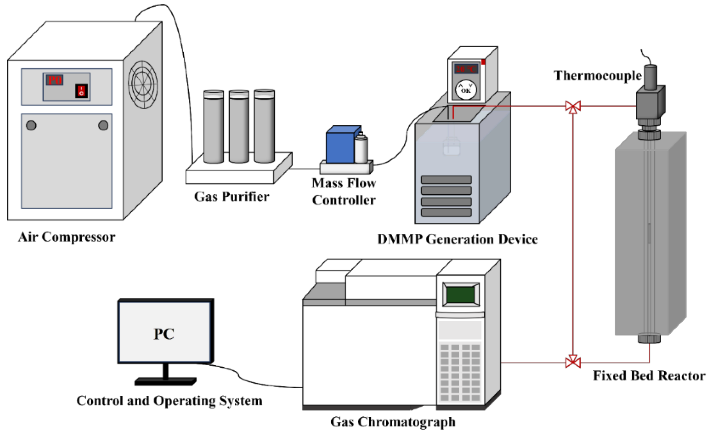
2.3. Performance Evaluation

Figure 1 shows the custom-built apparatus used to evaluate the thermocatalytic decomposition performance of the prepared catalysts. The apparatus comprised a DMMP generation device, fixed-bed reactor for the catalytic reaction and device for exhaust gas analysis. DMMP vapour was generated by the bubbling method, which introduced 50 mL/min of purified air into a DMMP generation bottle. The bottle was placed in a water bath at a constant temperature of 30 °C, and the DMMP concentration was controlled at 5.3 g/m3. A quartz tube with an inner diameter of 4 mm was placed in a vertical tubular resistance furnace with a programmable temperature control to act as the fixed-bed reactor. Each catalyst sample was pressed, crushed and sieved (20–40 mesh), after which it was used to fill the quartz tube. Both ends of the catalyst sample were fixed with quartz cotton, and the temperature of the fixed-bed reactor was set to 400 °C. The filling height was 2.4 cm, and the gas hourly space velocity was 9952 h−1. The loading amounts of m-ZrO2 nanoparticles, t-ZrO2 nanoparticles, m-ZrO2 flower-like shapes, t-ZrO2 flower-like shapes, m-ZrO2 hollow microspheres, and t-ZrO2 hollow microspheres were 0.4105, 0.4005, 0.4392, 0.4265, 0.3753, and 0.3762 g, respectively. The exhaust gas analysis device comprised a gas chromatograph (Agilent 6890N, Santa Clara, CA, USA) equipped with a flame ionisation detector and a DB-1701 column connected to a computer control terminal so that the changes in the DMMP concentration before and after the thermocatalytic decomposition could be monitored online. The generation bottles, fixed-bed reactor, and gas chromatograph were connected by pipelines kept at a constant temperature of 80 °C to prevent the DMMP vapour from condensing. To verify the thermal stability of DMMP at 400 °C, a blank experiment was conducted by introducing DMMP into an empty quartz tube without any catalyst. To minimise potential errors, complete DMMP conversion was defined as a conversion rate of ≥99%, and the protection time was defined as the amount time for complete DMMP conversion. The protection time is widely used to evaluate the thermocatalytic decomposition performance of a catalyst [26]. The conversion rate ( C V R D M M P ) is expressed as follows:
C V R D M M P = ( 1 C o u t C i n ) × 100 %
where Cout is the DMMP concentration in the exhaust gases after thermocatalytic decomposition, and Cin is the initial DMMP concentration generated by the bubbling.

2.4. Qualitative Analysis of the Exhaust Gases

After the thermocatalytic decomposition, the gaseous products were qualitatively analysed by using a microreactor (CATLAB) equipped with a mass spectrometer (HPR-20, Hiden Ltd., Warrington, UK). First, pure He was vented at a rate of 80 mL/min into the microreactor, which was loaded with 100 mg of a catalyst at room temperature (25 °C). The microreactor was then heated to 300 °C and kept for 2 h. When the temperature decreased to room temperature, a heating programme was started where an Ar/O2 mixture (80%/20%) was introduced at a flow rate of 50 mL/min into the DMMP generation bottle, which was kept at 10 °C. While maintaining the continuous flow of Ar/O2/DMMP mixture into the microreactor, the temperature was increased from room temperature to 400 °C at a rate of 10 °C/min. The exhaust gases were qualitatively analysed online by using the mass spectrometer (HPR-20).

3. Results

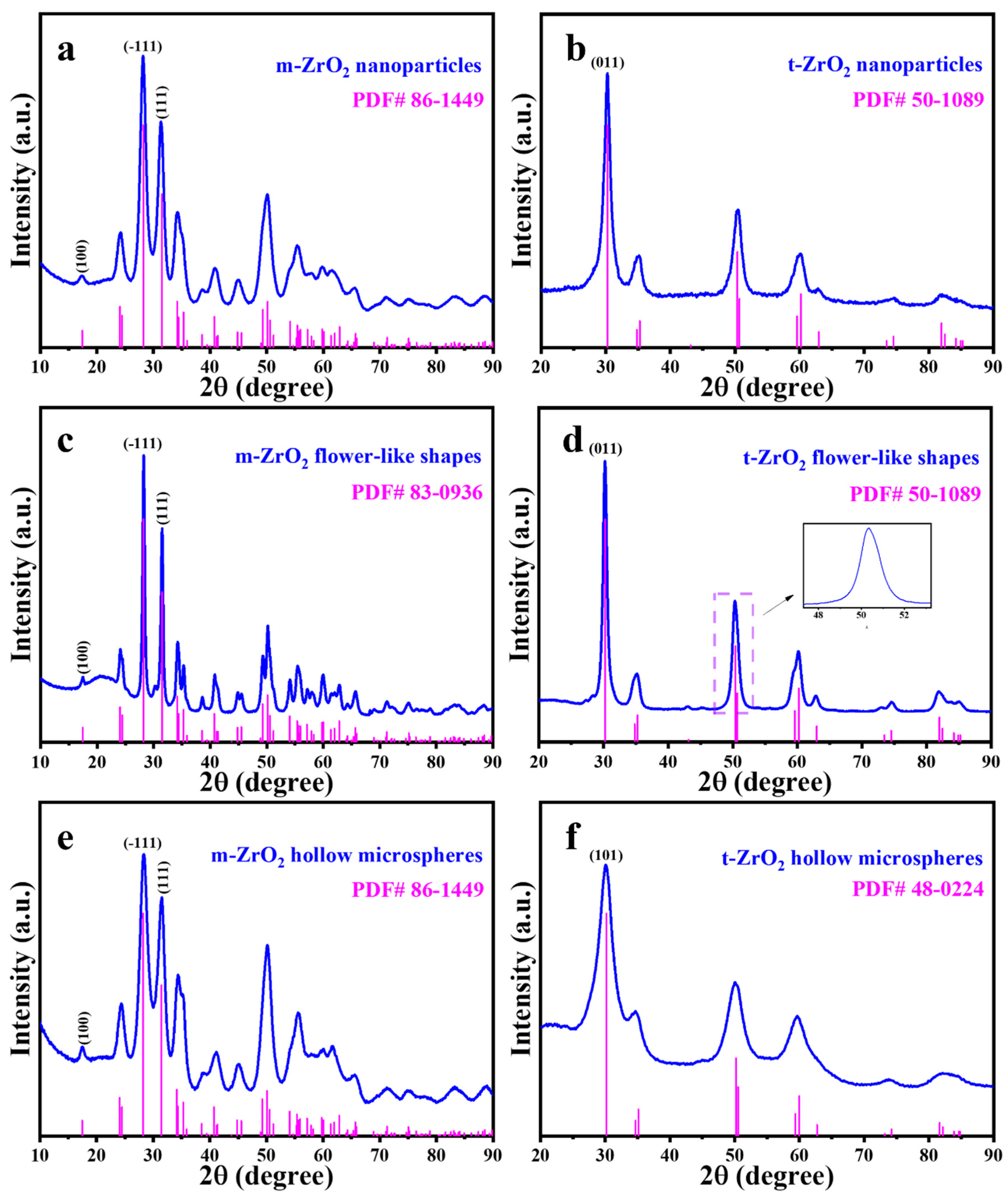
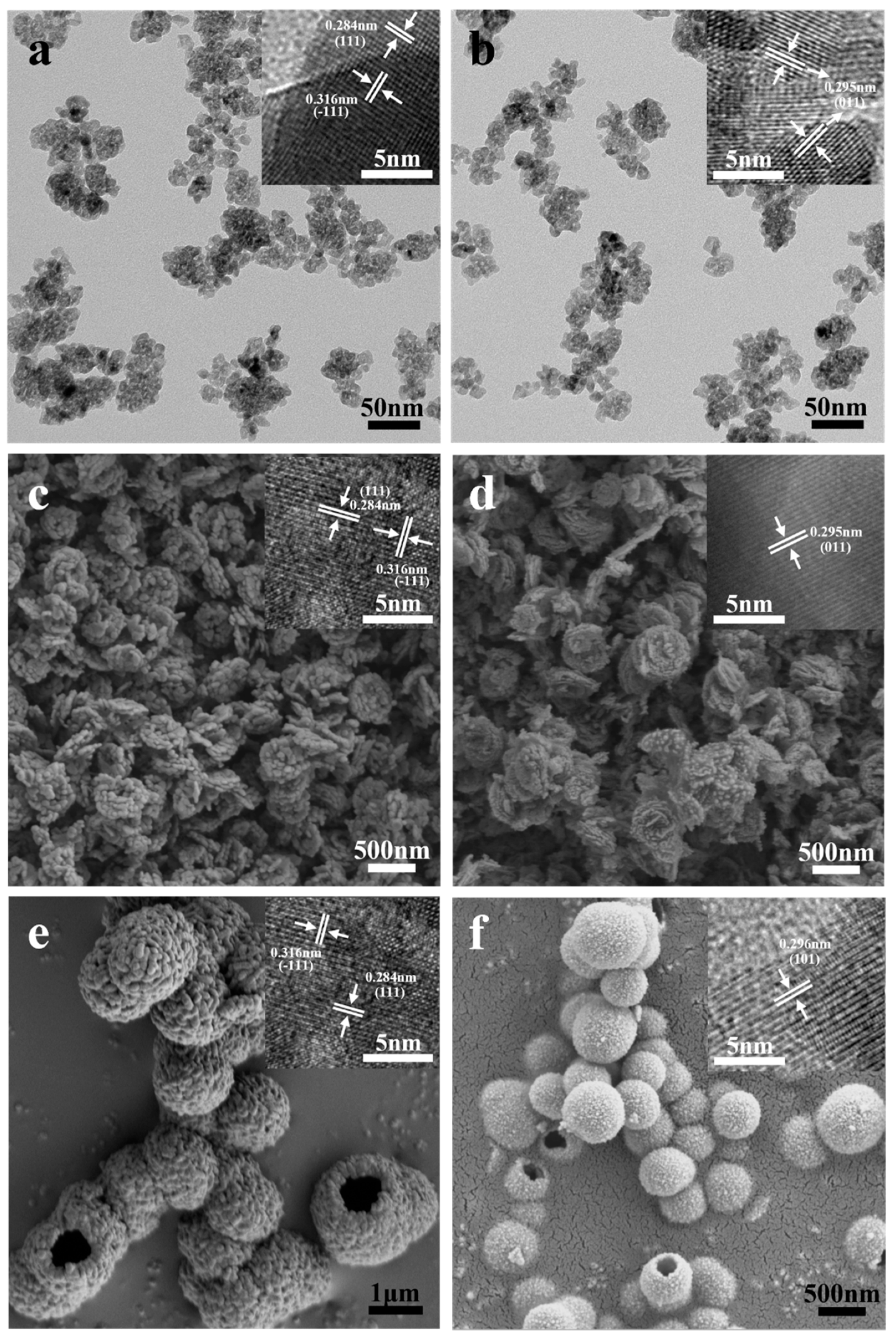
3.1. Crystalline Structures

Figure 2 presents the XRD patterns of the six prepared catalysts, and Figure 3 shows the HRTEM images. The characteristic peaks of the m-ZrO2 nanoparticles (Figure 2a) and hollow microspheres (Figure 2e) showed good agreement with the XRD spectrum of JCPDS No. 86-1449. The HRTEM images of the m-ZrO2 nanoparticles (Figure 3a) and hollow microspheres (Figure 3e) showed clear lattice stripes with spacings of 0.316 and 0.284 nm corresponding to the (−111) and (111) crystal planes, respectively. The characteristic peaks of the m-ZrO2 flower-like shapes (Figure 2c) showed good agreement with the XRD spectrum of JCPDS No. 83-0936. The lattice stripes had spacings of 0.316 and 0.284 nm, corresponding to the (−111) and (111) crystal planes, respectively. The characteristic peaks of the t-ZrO2 nanoparticles (Figure 2b) and flower-like shapes (Figure 2d) showed good agreement with the XRD spectrum of JCPDS No. 50-1089. The t-ZrO2 flower-like shapes had an asymmetric peak near 2θ = 50°, which is consistent with the results of Shu et al. [23] and which confirms that t-ZrO2 was synthesised. The HRTEM images of the t-ZrO2 nanoparticles (Figure 3b) and flower-like shapes (Figure 3d) showed a lattice spacing of 0.295 nm corresponding to the (011) crystal plane. Meanwhile, the characteristic peaks of the t-ZrO2 hollow microspheres (Figure 2f) showed good agreement with the XRD spectrum of JCPDS No. 48-0224, and the HRTEM image (Figure 3f) showed a lattice spacing of 0.296 nm, which corresponds to the (101) crystal plane. These results indicate that pure m- and t-ZrO2 were successfully synthesised.
Figure 3 also shows the SEM and TEM images of the six prepared catalysts. The particle size distribution of these six ZrO2 catalysts has been calculated using Nano Measure software and fitted with the Gaussian function (Figures S1–S6). The m- and t-ZrO2 nanoparticles (Figure 3a,b, respectively) had similar particle sizes of approximately 5 nm (Figures S1 and S2). The m- and t-ZrO2 flower-like shapes (Figure 3c,d, respectively) had a layered structure where each layer comprised rough nanoparticles. Each layer had the size of approximately 350 nm (Figures S3 and S4) and thickness of approximately 50 nm. The m- and t-ZrO2 hollow microspheres (Figure 3e,f, respectively) were formed by the aggregation of small nanoparticles. Moreover, the m-ZrO2 hollow microspheres were of various sizes with a range of 0.5–2.5 µm (Figure S5), while the t-ZrO2 hollow microspheres had a uniform size distribution of 200–800 nm (Figure S5). While the hollow microspheres were often individual, and some were twinned, so these catalysts often had a rough and notched surface.

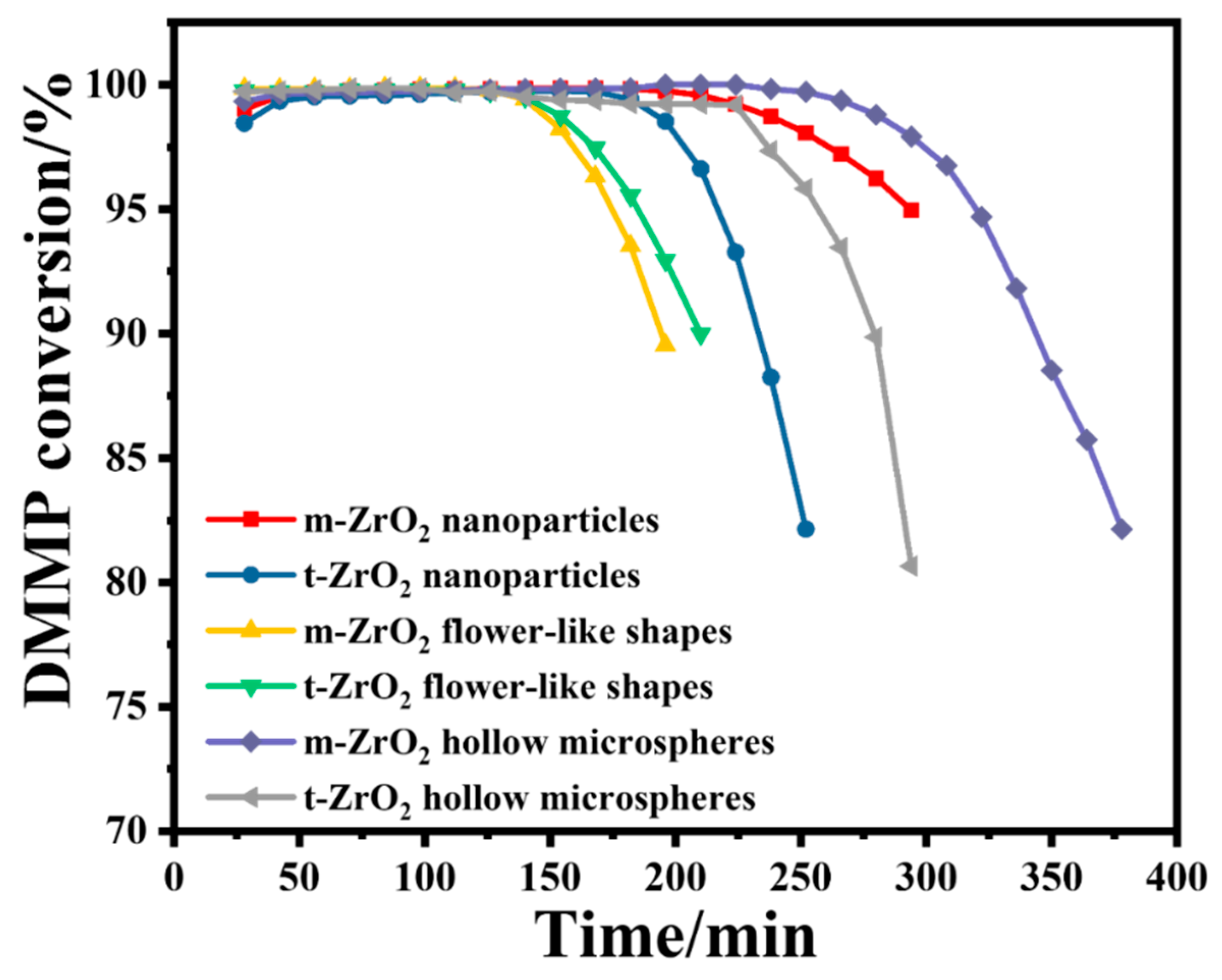
3.2. Catalytic Performance

Figure 4 shows the DMMP conversion rates of the six prepared catalysts over time, and Table 1 summarises the corresponding protection times. In terms of morphology, the ZrO2 hollow microspheres had the longest protection time, followed by the ZrO2 nanoparticles and ZrO2 flower-like shapes. In terms of the crystalline phase, the m-ZrO2 nanoparticles and hollow microspheres exhibited longer protection times than their t-ZrO2 counterparts. In contrast, the m-ZrO2 and t-ZrO2 flower-like shapes had the same protection time. Table 2 provides a comparison of protection time on various catalysts reported in the literature.
In the initial stage of thermocatalytic decomposition, DMMP micro-penetration appeared, and the activity of the ZrO2 catalysts gradually increased to a normal level. This phenomenon is common in fixed-bed reactors, which can be attributed to a slight deactivation of ZrO2 during storage. However, ZrO2 can be reactivated when the catalytic temperature increases to a certain threshold. As the reaction progressed, when the catalytic time exceeded the maximum protection time, DMMP began to break through, and the DMMP conversion rate sharply decreased, which indicates that the catalyst rapidly deactivated. Table 1 lists the specific surface areas of the prepared catalysts. The protection times of the catalysts appear to be associated with their specific surface areas. This may be because catalysts with a larger specific surface area have a stronger DMMP adsorption capacity, which promotes the catalytic reaction and increases the protection time. Among the six catalysts, the m-ZrO2 hollow microspheres had the largest specific surface area by far of 100.1 m2/g, and they exhibited the best catalytic performance with a protection time of up to 266 min. The t- and m-ZrO2 flower-like shapes, m-ZrO2 nanoparticles and t-ZrO2 hollow microspheres had similar specific surface areas and the same protection time.
To avoid the effect of different catalyst loadings on the protection time, the mass specific treatment capacity (MSTC) was calculated based on parameters such as the catalyst filling quality, protection time, gas hourly space velocity and occurrence concentration. The m-ZrO2 hollow microspheres had the best MSTC (0.189 gDMMP/gcat), followed by the t-ZrO2 hollow microspheres (0.158 gDMMP/gcat), m-ZrO2 nanoparticles (0.145 gDMMP/gcat), and t-ZrO2 nanoparticles (0.121 gDMMP/gcat). The m-ZrO2 flower-like shapes (0.085 gDMMP/gcat) and t-ZrO2 flower-like shapes (0.087 gDMMP/gcat) had the worst MSTC, which is consistent with the results for the protection time. The surface area-specific treatment capacity (SSTC) was also calculated, and the t-ZrO2 flower-like shapes had the best SSTC, which can be attributed to it having the lowest specific surface area.

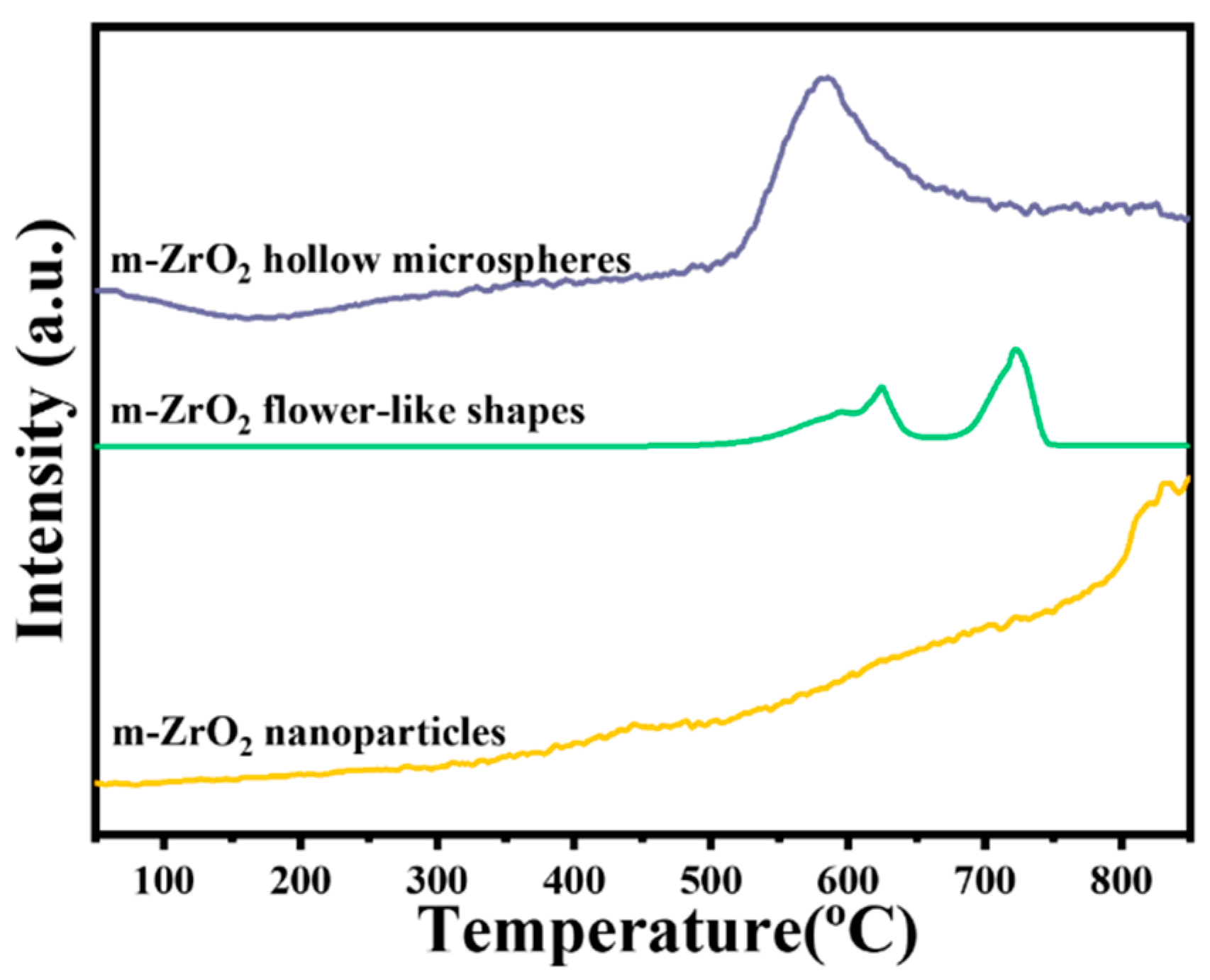
3.3. H2-TPR Analysis

Overall, the m-ZrO2 catalysts had longer protection times than the t-ZrO2 catalysts. Thus, the surface chemical properties of the m-ZrO2 catalysts were further explored. Figure 5 shows the H2-TPR curves of the m-ZrO2 hollow microspheres, flower-like shapes and nanoparticles. The m-ZrO2 hollow microspheres exhibited a weaker reduction peak between 200 °C and 500 °C than the other morphologies, indicating that the m-ZrO2 hollow microspheres had relatively high catalytic oxidation activity at low temperatures. Moreover, the m-ZrO2 hollow microspheres had a strong reduction peak around 590 °C, whereas the m-ZrO2 flower-like shapes displayed three consecutive peaks between 520 and 740 °C. The m-ZrO2 nanoparticles not only exhibited a very weak characteristic peak around 450 °C but also exhibited a weak reduction peak between 500 and 750 °C. The hydrogen consumption (i.e., reduction peak area) of m-ZrO2 hollow microspheres was markedly greater than that of m-ZrO2 flower-like shapes and nanoparticles, which indicates that the m-ZrO2 hollow microspheres had stronger oxidation activity.

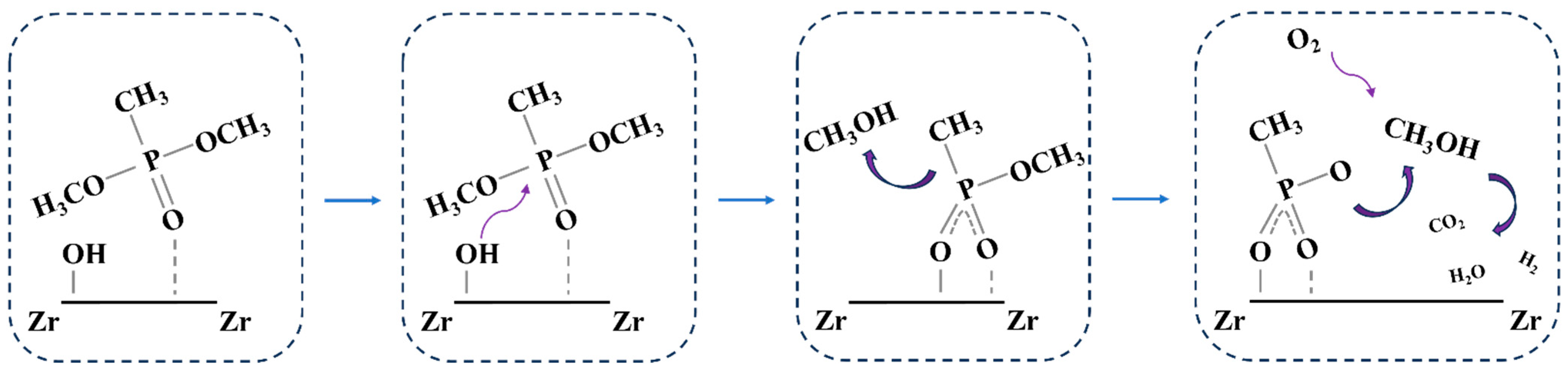
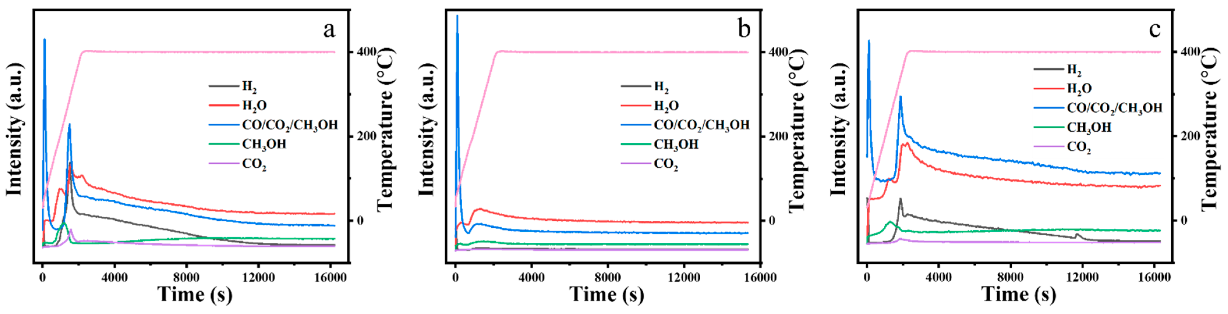
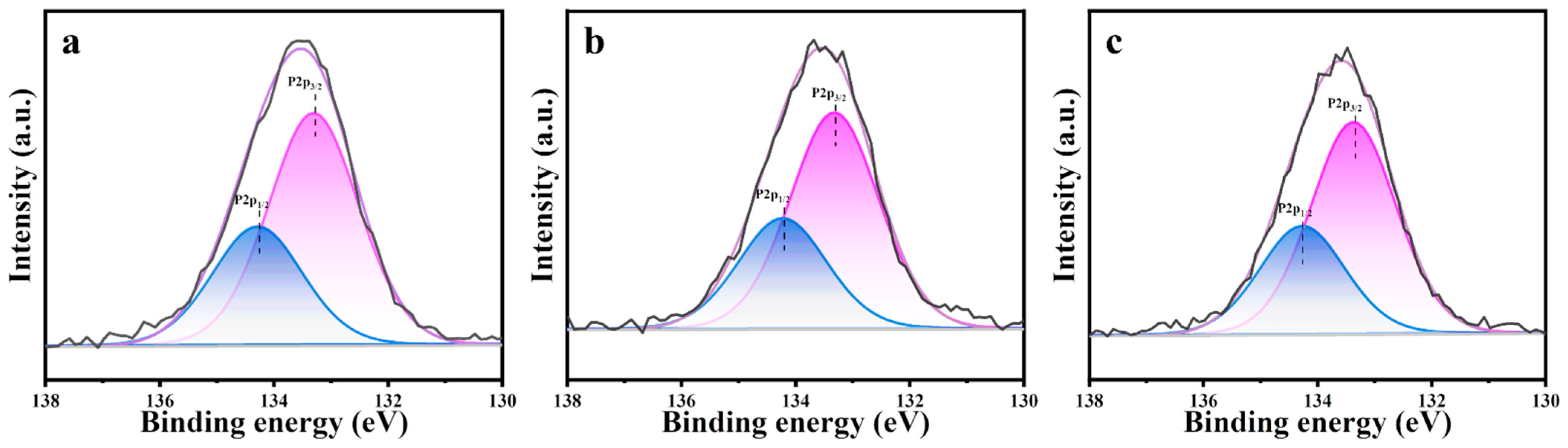
3.4. Thermocatalytic Decomposition Mechanism

Figure 6 shows the mass spectrometry results for the exhaust gases of the m-ZrO2 catalysts. The three m-ZrO2 catalysts had the same gaseous products, including methanol, H2O, H2, and CO2. The formation of methanol is associated with the elimination of the methoxy group in DMMP, and methanol can further be oxidised to generate H2O, H2, and CO2 [29,30,31,32,33,34].
Figure 7 shows the X-ray photoelectron spectroscopy results for the m-ZrO2 catalysts, which were obtained to investigate the residues produced on the catalysts after the thermocatalytic decomposition. The P2p spectrum was detected on the surface of all three m-ZrO2 catalysts, which indicates that P-containing by-products remained on the catalysts after they were used. The P2p spectra were fitted to two peaks at 133.2 and 134.3 eV. The latter peak was attributed to the residual DMMP molecules on the m-ZrO2 surface after the thermocatalytic decomposition [35], and the former was ascribed to phosphorus oxide species remaining on the catalyst surface from the complete or incomplete decomposition of DMMP [35]. Based on results in the literature [33,34,36] as well as the exhaust gas and surface products after thermocatalytic decomposition, the reaction mechanism can be deduced as follows. DMMP molecules first adsorbed on the catalyst surface through the P=O bond, and the P–O bond in the P–OCH3 group is broken to generate gaseous methanol and solid phosphorus oxide by-products. The methanol is further oxidised to gaseous CO2, H2, and H2O, whereas the solid phosphorus oxide by-products are deposited on the catalyst surface, which leads to catalyst deactivation, as shown in Figure 8.

4. Discussion

In this study, six types of ZrO2 catalysts with nanoparticle, flower-like shape and hollow microsphere morphologies in monoclinic and tetragonal phases were synthesized, and their thermocatalytic decomposition performance for DMMP was studied. In terms of protection time, m-ZrO2 catalysts exhibited superior performance to t-ZrO2 catalysts in the thermocatalytic decomposition of DMMP. For a given crystalline phase, ZrO2 hollow microspheres performed better than ZrO2 flower-like shapes and nanoparticles. Among the six catalyst materials, m-ZrO2 hollow microspheres exhibited the best MSTC and the longest protection time of 266 min at 400 °C, but t-ZrO2 flower-like shapes exhibited the best SSTC. The exhaust gases and surface by-products of the catalysts were analysed to deduce the deactivation mechanism, it is inferred that the reaction paths of the three morphologies of m-ZrO2 on the catalytic decomposition of DMMP are similar. The deposition of phosphorus oxide by-products on the catalyst surface led to the loss of catalyst active sites. The results of this study helped us to obtain a deep and systematic understanding of the thermocatalytic decomposition of DMMP by ZrO2 catalysts with different morphologies and crystalline phases. The findings are expected to provide guidance for designing high-performance ZrO2-based composite catalysts for the degradation of chemical warfare agents.

Supplementary Materials

The following supporting information can be downloaded at: https://www.mdpi.com/article/10.3390/nano14070611/s1, Figure S1. TEM image (a) and particle size distribution of m-ZrO2 nanoparticles (b). Figure S2. TEM image (a) and particle size distribution of t-ZrO2 nanoparticles (b). Figure S3. TEM image (a) and particle size distribution of m-ZrO2 with flower-like shapes (b). Figure S4. TEM image (a) and particle size distribution of t-ZrO2 with flower-like shapes (b). Figure S5. TEM image (a) and particle size distribution of m-ZrO2 with hollow microspheres (b). Figure S6. TEM image (a) and particle size distribution of t-ZrO2 with hollow microspheres (b).

Author Contributions

Methodology, X.W. and Z.Z.; Formal analysis, X.W., P.S., Z.Z. and Y.L.; Data curation, X.W.; Writing—original draft, X.W.; Writing—review & editing, S.Z.; Visualization, X.W. and S.Z.; Supervision, P.Y. and Y.D.; Project administration, Y.D. All authors have read and agreed to the published version of the manuscript.

Funding

This work was financially supported by the National Natural Science Foundation of China (No. 21701186) and the Fundamental Research Funds from the State Key Laboratory of NBC Protection for Civilian (SKLNBC 2019-04), China.

Data Availability Statement

Data are contained within the article and Supplementary Materials.

Conflicts of Interest

The authors declare no conflicts of interest.

References

  1. Abou-Donia, M.B.; Siracuse, B.; Gupta, N.; Sobel Sokol, A. Sarin (GB, O-Isopropyl Methylphosphonofluoridate) Neurotoxicity: Critical Review. Crit. Rev. Toxicol. 2016, 46, 845–875. [Google Scholar] [CrossRef] [PubMed]
  2. Yousef Motamedhashemi, M.M.; Monji, M.; Egolfopoulos, F.; Tsotsis, T. A Hybrid Catalytic Membrane Reactor for Destruction of a Chemical Warfare Simulant. J. Membr. Sci. 2015, 473, 1–7. [Google Scholar] [CrossRef]
  3. Kiani, S.S.; Farooq, A.; Ahmad, M.; Irfan, N.; Nawaz, M.; Irshad, M.A. Impregnation on Activated Carbon for Removal of Chemical Warfare Agents (CWAs) and Radioactive Content. Environ. Sci. Pollut. Res. 2021, 28, 60477–60494. [Google Scholar] [CrossRef] [PubMed]
  4. Tsyshevsky, R.; Head, A.R.; Trotochaud, L.; Bluhm, H.; Kuklja, M.M. Mechanisms of Degradation of Toxic Nerve Agents: Quantum-Chemical Insight into Interactions of Sarin and Soman with Molybdenum Dioxide. Surf. Sci. 2020, 700, 121639. [Google Scholar] [CrossRef]
  5. Šťastný, M.; Štengl, V.; Henych, J.; Tolasz, J.; Kormunda, M.; Ederer, J.; Issa, G.; Janoš, P. Synthesis and Characterization of TiO2/Mg(OH)2 Composites for Catalytic Degradation of CWA Surrogates. RSC Adv. 2020, 10, 19542–19552. [Google Scholar] [CrossRef] [PubMed]
  6. Neupane, S.; Rahman, R.K.; Baker, J.; Arafin, F.; Ninnemann, E.; Thurmond, K.; Wang, C.-H.; Masunov, A.E.; Vasu, S.S. DMMP Pyrolysis and Oxidation Studies at High Temperature inside a Shock Tube Using Laser Absorption Measurements of CO. Combust. Flame 2020, 214, 14–24. [Google Scholar] [CrossRef]
  7. McEntee, M.; Gordon, W.O.; Balboa, A.; Delia, D.J.; Pitman, C.L.; Pennington, A.M.; Rolison, D.R.; Pietron, J.J.; DeSario, P.A. Mesoporous Copper Nanoparticle/TiO2 Aerogels for Room-Temperature Hydrolytic Decomposition of the Chemical Warfare Simulant Dimethyl Methylphosphonate. ACS Appl. Nano Mater. 2020, 3, 3503–3512. [Google Scholar] [CrossRef]
  8. Iwai, T.; Inoue, H.; Kakegawa, K.; Ohrui, Y.; Nagoya, T.; Nagashima, H.; Miyahara, H.; Chiba, K.; Seto, Y.; Okino, A. Development of a High-Efficiency Decomposition Technology for Volatile Chemical Warfare Agent Sarin Using Dielectric Barrier Discharge. Plasma Chem. Plasma Process. 2020, 40, 907–920. [Google Scholar] [CrossRef]
  9. Jeon, S.; Schweigert, I.V.; Pehrsson, P.E.; Balow, R.B. Kinetics of Dimethyl Methylphosphonate Adsorption and Decomposition on Zirconium Hydroxide Using Variable Temperature In Situ Attenuated Total Reflection Infrared Spectroscopy. ACS Appl. Mater. Interfaces 2020, 12, 14662–14671. [Google Scholar] [CrossRef]
  10. Jiang, Z.; Jing, M.; Feng, X.; Xiong, J.; He, C.; Douthwaite, M.; Zheng, L.; Song, W.; Liu, J.; Qu, Z. Stabilizing Platinum Atoms on CeO2 Oxygen Vacancies by Metal-Support Interaction Induced Interface Distortion: Mechanism and Application. Appl. Catal. B Environ. Energy 2020, 278, 119304. [Google Scholar] [CrossRef]
  11. Segal, S.R.; Cao, L.; Suib, S.L.; Tang, X.; Satyapal, S. Thermal Decomposition of Dimethyl Methylphosphonate over Manganese Oxide Catalysts. J. Catal. 2001, 198, 66–76. [Google Scholar] [CrossRef]
  12. Gao, H.; Kong, W.; Zhou, S.; Wang, X.; He, Q.; Dong, Y. Thermal Catalytic Decomposition of Dimethyl Methyl Phosphonate Using CuO-CeO2/γ-Al2O3. Appl. Sci. 2022, 12, 10101. [Google Scholar] [CrossRef]
  13. Tzou, T.Z.; Weller, S.W. Catalytic Oxidation of Dimethyl Methylphosphonate. J. Catal. 1994, 146, 370–374. [Google Scholar] [CrossRef]
  14. Walenta, C.A.; Xu, F.; Tesvara, C.; O’Connor, C.R.; Sautet, P.; Friend, C.M. Facile Decomposition of Organophosphonates by Dual Lewis Sites on a Fe3O4(111) Film. J. Phys. Chem. C 2020, 124, 12432–12441. [Google Scholar] [CrossRef]
  15. HE, M. Infrared Studies of the Adsorption of Synthesis Gas on Zirconium Dioxide. J. Catal. 1984, 87, 381–388. [Google Scholar] [CrossRef]
  16. Ananchenko, D.V.; Nikiforov, S.V.; Sobyanin, K.V.; Konev, S.F.; Dauletbekova, A.K.; Akhmetova-Abdik, G.; Akilbekov, A.T.; Popov, A.I. Paramagnetic Defects and Thermoluminescence in Irradiated Nanostructured Monoclinic Zirconium Dioxide. Materials 2022, 15, 8624. [Google Scholar] [CrossRef] [PubMed]
  17. Jung, K.T.; Bell, A.T. The Effects of Synthesis and Pretreatment Conditions on the Bulk Structure and Surface Properties of Zirconia. J. Mol. Catal. Chem. 2000, 163, 27–42. [Google Scholar] [CrossRef]
  18. Denchy, M.A.; Wang, L.; Blando, N.; Hansen, L.; Bilik, B.R.; Tang, X.; Hicks, Z.; Gantefoer, G.; Bowen, K.H. Adsorption and Decomposition of Dimethyl Methylphosphonate on Size-Selected Zirconium Oxide Trimer Clusters. J. Phys. Chem. C 2021, 125, 23688–23698. [Google Scholar] [CrossRef]
  19. Long, J.W.; Chervin, C.N.; Balow, R.B.; Jeon, S.; Miller, J.B.; Helms, M.E.; Owrutsky, J.C.; Rolison, D.R.; Fears, K.P. Zirconia-Based Aerogels for Sorption and Degradation of Dimethyl Methylphosphonate. Ind. Eng. Chem. Res. 2020, 59, 19584–19592. [Google Scholar] [CrossRef]
  20. Jeon, S.; Balow, R.B.; Daniels, G.C.; Ko, J.S.; Pehrsson, P.E. Conformal Nanoscale Zirconium Hydroxide Films for Decomposing Chemical Warfare Agents. ACS Appl. Energy Mater. 2019, 2, 2295–2307. [Google Scholar] [CrossRef]
  21. Balow, R.B.; Lundin, J.G.; Daniels, G.C.; Gordon, W.O.; McEntee, M.; Peterson, G.W.; Wynne, J.H.; Pehrsson, P.E. Environmental Effects on Zirconium Hydroxide Nanoparticles and Chemical Warfare Agent Decomposition: Implications of Atmospheric Water and Carbon Dioxide. ACS Appl. Mater. Interfaces 2017, 9, 39747–39757. [Google Scholar] [CrossRef] [PubMed]
  22. Li, W.; Huang, H.; Li, H.; Zhang, W.; Liu, H. Facile Synthesis of Pure Monoclinic and Tetragonal Zirconia Nanoparticles and Their Phase Effects on the Behavior of Supported Molybdena Catalysts for Methanol-Selective Oxidation. Langmuir 2008, 24, 8358–8366. [Google Scholar] [CrossRef]
  23. Shu, Z.; Jiao, X.; Chen, D. Synthesis and Photocatalytic Properties of Flower-like Zirconia Nanostructures. CrystEngComm 2012, 14, 1122–1127. [Google Scholar] [CrossRef]
  24. Lin, F.-Q.; Dong, W.-S.; Liu, C.-L.; Liu, Z.; Li, M. In Situ Source–Template-Interface Reaction Route to Hollow ZrO2 Microspheres with Mesoporous Shells. J. Colloid Interface Sci. 2008, 323, 365–371. [Google Scholar] [CrossRef]
  25. Shu, Z. Template-Free Solvothermal Synthesis of Size-Controlled Yttria-Stabilized-Zirconia Hollow Spheres. J. Alloys Compd. 2011, 509, 9200–9206. [Google Scholar] [CrossRef]
  26. Cao, L.; Segal, S.R.; Suib, S.L.; Tang, X.; Satyapal, S. Thermocatalytic Oxidation of Dimethyl Methylphosphonate on Supported Metal Oxides. J. Catal. 2000, 194, 61–70. [Google Scholar] [CrossRef]
  27. Lee, K.Y.; Houalla, M.; Hercules, D.M.; Hall, W.K. Catalytic Oxidative Decomposition of Dimethyl Methylphosphonate over Cu-Substituted Hydroxyapatite. J. Catal. 1994, 145, 223–231. [Google Scholar] [CrossRef]
  28. Graven, W.M.; Weller, S.W.; Peters, D.L. Catalytic Conversion of Organophosphate Vapor over Platinum-Alumina. Ind. Eng. Chem. Process Des. Dev. 1966, 5, 183–189. [Google Scholar] [CrossRef]
  29. Kong, W.; Wang, X.; Wang, K.; He, Q.; Zhou, S.; Yang, P.; Dong, Y. Thermocatalytic Decomposition of Dimethyl Methylphosphonate Based on CeO2 Catalysts with Different Morphologies. Appl. Sci. 2023, 13, 3093. [Google Scholar] [CrossRef]
  30. Kong, W.; Zhou, S.; Wang, X.; He, Q.; Yang, P.; Yuan, Y.; Dong, Y. Catalytic Oxidative Decomposition of Dimethyl Methyl Phosphonate over CuO/CeO2 Catalysts Prepared Using a Secondary Alkaline Hydrothermal Method. Catalysts 2022, 12, 1277. [Google Scholar] [CrossRef]
  31. Wang, L.; Denchy, M.; Blando, N.; Hansen, L.; Bilik, B.; Tang, X.; Hicks, Z.; Bowen, K.H. Thermal Decomposition of Dimethyl Methylphosphonate on Size-Selected Clusters: A Comparative Study between Copper Metal and Cupric Oxide Clusters. J. Phys. Chem. C 2021, 125, 11348–11358. [Google Scholar] [CrossRef]
  32. Mukhopadhyay, S.; Schoenitz, M.; Dreizin, E.L. Vapor-Phase Decomposition of Dimethyl Methylphosphonate (DMMP), a Sarin Surrogate, in Presence of Metal Oxides. Def. Technol. 2020, 17, 1095–1114. [Google Scholar] [CrossRef]
  33. Mitchell, M.B.; Sheinker, V.N.; Mintz, E.A. Adsorption and Decomposition of Dimethyl Methylphosphonate on Metal Oxides. J. Phys. Chem. B 1997, 101, 11192–11203. [Google Scholar] [CrossRef]
  34. Chen, D.A.; Ratliff, J.S.; Hu, X.; Gordon, W.O.; Senanayake, S.D.; Mullins, D.R. Dimethyl Methylphosphonate Decomposition on Fully Oxidized and Partially Reduced Ceria Thin Films. Surf. Sci. 2010, 604, 574–587. [Google Scholar] [CrossRef]
  35. Ma, S.; Zhou, J.; Kang, Y.C.; Reddic, J.E.; Chen, D.A. Dimethyl Methylphosphonate Decomposition on Cu Surfaces: Supported Cu Nanoclusters and Films on TiO2(110). Langmuir 2004, 20, 9686–9694. [Google Scholar] [CrossRef]
  36. Rusu, C.N.; Yates, J.T. Adsorption and Decomposition of Dimethyl Methylphosphonate on TiO2. J. Phys. Chem. B 2000, 104, 12292–12298. [Google Scholar] [CrossRef]
Figure 1. Schematic of the custom-built apparatus for evaluation of the thermocatalytic decomposition performance.
Nanomaterials 14 00611 g001
Figure 2. XRD spectra of ZrO2 catalysts: m-ZrO2 (a) nanoparticles, (c) flower-like shapes and (e) hollow microspheres; t-ZrO2 (b) nanoparticles, (d) flower-like shapes and (f) hollow microspheres.
Nanomaterials 14 00611 g002
Figure 3. TEM and HRTEM images of ZrO2 catalysts: (a) m-ZrO2 nanoparticles and (b) t-ZrO2 nanoparticles; SEM and HRTEM images of ZrO2 catalysts: (c) m-ZrO2 with flower-like shapes, (d) t-ZrO2 with flower-like shapes, (e) m-ZrO2 with hollow microspheres, and (f) t-ZrO2 with hollow microspheres.
Nanomaterials 14 00611 g003
Figure 4. DMMP conversion rates over time of the six ZrO2 catalysts.
Nanomaterials 14 00611 g004
Figure 5. H2-TPR curves of the m-ZrO2 catalysts with different morphologies.
Nanomaterials 14 00611 g005
Figure 6. Mass spectrometry results for the exhaust gases from the thermocatalytic decomposition of DMMP by the m-ZrO2 catalysts: (a) nanoparticles, (b) flower-like shapes, and (c) hollow microspheres (The pink line is the curve of the heating program).
Nanomaterials 14 00611 g006
Figure 7. XPS spectra (P2p) of m-ZrO2 (a) nanoparticles, (b) flower-like shapes, and (c) hollow microspheres.
Nanomaterials 14 00611 g007
Figure 8. Proposed reaction mechanism for DMMP decomposition.
Nanomaterials 14 00611 g008
Table 1. Specific surface area, filling quality, and catalytic performance of the six ZrO2 catalysts.
MorphologyCrystalline PhaseBET (m2/g)Filling Quality (g)Protection Time (min)MSTC
gDMMP/gcat
SSTC
gDMMP/Scat
NanoparticleMonoclinic88.70.41052240.1450.00067
Tetragonal66.10.40051820.1210.00073
Flower-like shapeMonoclinic38.70.43921400.0850.00096
Tetragonal23.10.42651400.0870.00161
Hollow microsphereMonoclinic100.10.37532660.1890.00071
Tetragonal88.30.37622240.1580.00067
Table 2. A comparison of protection time on various catalysts.
ReferenceCatalystReaction ConditionProtection Time
Lee et al. [27]Cu2-HA400 °C,
DMMP concentration 3.58 g/m3,
flow rate 100 mL/min
7.5 h
1.6%Pt-TiO2300 °C,
DMMP concentration 3.58 g/m3,
flow rate 100 mL/min
8 h
Graven et al. [28]0.5%Pt-Al2O3299 °C,
DMMP concentration 3.5 g/m3,
flow rate 8.85 L/min
8 h
Cao et al. [26]10% V/Al2O3400 °C,
DMMP concentration 1300 ppm,
flow rate 50 mL/min
12.5 h
1% Pt/Al2O38.5 h
10% Cu/Al2O37.5 h
Al2O34.0 h
10% Fe/Al2O33.5 h
10% Ni/Al2O31.5 h
10% V/SiO225 h
Gao et al. [12]CuO/γ-Al2O3350 °C,
DMMP concentration 4.0 g/m3,
flow rate 100 mL/min
1.8 h
CuO-1% CeO2/γ-Al2O32.1 h
CuO-5% CeO2/γ-Al2O33.9 h
CuO-10% CeO2/γ-Al2O31.8 h
Kong et al. [29]2MCeO2np300 °C,
DMMP concentration 5.32 g/m3,
flow rate 50 mL/min
5.8 h
6MCeO2nr7.0 h
12MCeO2nr8.1 h
6MCeO2nc3.5 h
12MCeO2nc6.3 h
Kong et al. [30]CeO2400 °C,
DMMP concentration 8.46 g/m3,
flow rate 100 mL/min
2.33 h
10% Cu/Ce4.2 h
20% Cu/Ce4.43 h
50% Cu/Ce5.36 h
80% Cu/Ce2.33 h
CuO0.93 h
This workm-ZrO2 nanoparticles400 °C,
DMMP concentration 5.3 g/m3,
flow rate 50 mL/min
3.73 h
t-ZrO2 nanoparticles3.03 h
m-ZrO2 flower-like shapes2.33 h
t-ZrO2 flower-like shapes2.33 h
m-ZrO2 hollow microspheres4.43 h
t-ZrO2 hollow microspheres3.73 h
Disclaimer/Publisher’s Note: The statements, opinions and data contained in all publications are solely those of the individual author(s) and contributor(s) and not of MDPI and/or the editor(s). MDPI and/or the editor(s) disclaim responsibility for any injury to people or property resulting from any ideas, methods, instructions or products referred to in the content.

